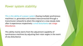
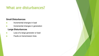
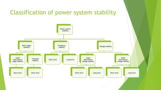
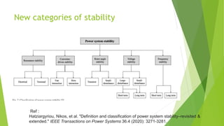
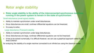
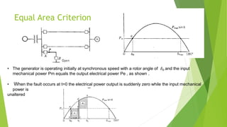
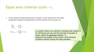
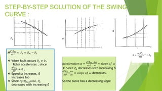
SlideShare a Scribd company logo
1 of 71
Power system stability
What is Stability?
Power system stability
This is the ability of a power system (having multiple synchronous
machines i.e. generators and motors interconnected through a
transmission network) to attain the original or a new steady state
after it experiences respectively a small disturbance or a large
disturbance.
This ability mainly stems from the adjustment capability of
synchronous machines by adjusting their rotor angles in the event
of any disturbance
What are disturbances?
Small Disturbances
 Incremental changes in load
 Incremental changes in generation
2 Large Disturbances
 Loss of a large generator or load
 Faults on transmission lines
Types of stability
 The stability arising from small disturbance (e.g.
change in AVR gain parameter, gradual or slow
variation in load or generation etc.) is termed
steady state stability
 The stability arising from a large disturbance (e.g. fault, line
switching, sudden large load or generation change) is termed
transient stability
Classification of power system stability
Power system
stability
Rotor angle
stability
Small
disturbance
angle stability
Short term
Transient
stability
Short term
Frequency
stability
Short term Long term
Voltage stability
Large
disturbance
voltage stability
Short term Long term
Small
disturbance
voltage stability
Short term Long term
New categories of stability
Ref :
Hatziargyriou, Nikos, et al. "Definition and classification of power system stability–revisited &
extended." IEEE Transactions on Power Systems 36.4 (2020): 3271-3281.
Rotor angle stability
 Rotor angle stability is the ability of the interconnected synchronous machines
running in the power system to remain in the state of synchronism.
Small disturbance (small signal) stability
 Ability to maintain synchronism under small disturbances.
 Since disturbances are small, nonlinear differential equations can be linearized.
 It is easy to solve.
2 Large disturbance (Transient) stability
 Ability to maintain synchronism under large disturbances.
 Since disturbances are large, nonlinear differential equations can not be linearized.
 It has to be solved numerically. It is difficult.However, we can use a graphical approach called Equal
Area Criterion
for analyzing the stability of a single machine connected to an infinite bus using the classical model.
Rotor angle and synchronous machine
Swing equation
 Swing equation describes the rotor dynamics for a synchronous machine
Consider a synchronous generator developing an electromagnetic torque Te(and
a corresponding electromagnetic power Pe) while operating at the synchronous
speed ws. If the input torque provided by the prime mover.
Swing equation
𝜏 = 𝐼𝛼
𝐽
𝑑2
𝜃𝑚
𝑑𝑡2 = 𝑇𝑎 = 𝑇𝑚 − 𝑇𝑒
𝜃𝑚 = 𝜔𝑠𝑚𝑡 + 𝛿𝑚
𝑑𝜃𝑚
𝑑𝑡
= 𝜔𝑠𝑚 +
𝑑𝛿𝑚
𝑑𝑡
𝑑2
𝜃𝑚
𝑑𝑡2
=
𝑑2
𝛿𝑚
𝑑𝑡2
𝐽
𝑑2𝛿𝑚
𝑑𝑡2 = 𝑇𝑎 = 𝑇𝑚 − 𝑇𝑒
Swing equation (cont.)
 𝐽𝜔𝑚
𝑑2𝛿𝑚
𝑑𝑡2 = 𝑃𝑎 = 𝑃𝑚 − 𝑃𝑒 Multiplying both sides by ωm and substituting P =
T ωm )
 M
𝑑2𝛿𝑚
𝑑𝑡2 = 𝑃𝑎 = 𝑃𝑚 − 𝑃𝑒
M= Jωm is inertia constant or angular
momentum of rotor at sync. speed
M
𝑑2𝛿𝑚
𝑑𝑡2 = 𝑃𝑎 = 𝑃𝑚 − 𝑃𝑒
2𝐻𝑆𝑚𝑎𝑐ℎ
𝜔𝑠𝑚
𝑑2
𝛿𝑚
𝑑𝑡2
= 𝑃𝑎 = 𝑃𝑚 − 𝑃𝑒
M=
2𝐻𝑆𝑚𝑎𝑐ℎ
𝜔𝑠𝑚
MJ/mech rad
H is another inertia constant
Swing equation (cont.)
2𝐻𝑆𝑚𝑎𝑐ℎ
𝜔𝑠𝑚
𝑑2𝛿𝑚
𝑑𝑡2
= 𝑃𝑎 = 𝑃𝑚 − 𝑃𝑒
2𝐻
𝜔𝑠𝑚
𝑑2
𝛿𝑚
𝑑𝑡2
=
𝑃𝑎
𝑆𝑚𝑎𝑐ℎ
=
𝑃𝑚 − 𝑃𝑒
𝑆𝑚𝑎𝑐ℎ
2𝐻
𝜔𝑠
𝑑2𝛿
𝑑𝑡2 = 𝑃𝑎 = 𝑃𝑚 − 𝑃𝑒 per unit
Swing equation (cont.)
𝐻
𝜋𝑓
𝑑2𝛿
𝑑𝑡2= 𝑃𝑎 = 𝑃𝑚 − 𝑃𝑒 per unit

𝐻
180𝑓
𝑑2𝛿
𝑑𝑡2= 𝑃𝑎 = 𝑃𝑚 − 𝑃𝑒 per unit
𝛿 𝑖𝑠 𝑡ℎ𝑒 𝑎𝑛𝑔𝑙𝑒 𝑤𝑖𝑡ℎ 𝑟𝑒𝑠𝑝𝑒𝑐𝑡 𝑡𝑜 𝑎 𝑠𝑦𝑛𝑐ℎ𝑟𝑜𝑛𝑜𝑢𝑠𝑙𝑦 𝑟𝑜𝑡𝑎𝑡𝑖𝑛𝑔 𝑟𝑒𝑓𝑒𝑟𝑛𝑐𝑒 𝑎𝑥𝑖𝑠,
𝑑𝛿
𝑑𝑡
𝑖𝑠 𝑡ℎ𝑒 𝑑𝑖𝑓𝑓𝑒𝑟𝑒𝑛𝑐𝑒 𝑓𝑟𝑜𝑚 𝑠𝑦𝑛𝑐ℎ𝑟𝑜𝑛𝑜𝑢𝑠 𝑠𝑝𝑒𝑒𝑑
If swing equation is referred to system base in multi machine system, then all powers in pu and H
needs to be converted as follows
𝐻𝑠𝑦𝑠𝑡𝑒𝑚 = 𝐻𝑚𝑎𝑐ℎ
𝑆𝑚𝑎𝑐 ℎ
𝑆𝑠𝑦𝑠𝑡𝑒𝑚
Coherently swinging machine
 Machine 1
2𝐻1
𝜔𝑠
𝑑2𝛿1
𝑑𝑡2 = 𝑃𝑎1 = 𝑃𝑚1 − 𝑃𝑒1 per unit---------------------(1)
2𝐻2
𝜔𝑠
𝑑2𝛿2
𝑑𝑡2 = 𝑃𝑎2 = 𝑃𝑚2 − 𝑃𝑒2 per unit-----------------(2)
Machine 2
Since δ1 = δ2= δ, Adding (1) and (2)
2𝐻
𝜔𝑠
𝑑2𝛿
𝑑𝑡2 = 𝑃𝑎 = 𝑃𝑚 − 𝑃𝑒 per unit
Where H= H1+H2
(
2𝐻1
𝜔𝑠
+
2𝐻2
𝜔𝑠
)
𝑑2𝛿
𝑑𝑡2= (𝑃𝑚1+ 𝑃𝑚2 )- (𝑃𝑒1+ 𝑃𝑒2 )
example
Calculate equivalent H constant.
Machines which swing
together are called
coherent machines
Non coherent machine
Since δ1 ≠ δ2. And Power flow from the machine with
greater δ to lower δ. Lets assume δ1 > δ2
Non coherent machine (cont)
 A noteworthy application of these equations concerns a two- machine system having only one
generator (machine one) and a synchronous motor (machine two) connected by a network of pu
reactances. Whatever change occurs in the generator output is thus absorbed by the motor, and
we can write
In order to be stable the angular differences betweenmachines must
decrease after the final switching operation-such as the opening of circuit
breaker to clear a fault .
Power angle equation
𝑃𝑘 + 𝑗𝑄𝑘 = 𝑉𝑘𝐼𝑘 ∗
𝐼𝑏𝑢𝑠 = 𝑌𝑏𝑢𝑠𝑉𝑏𝑢𝑠
𝑃1 + 𝑗 𝑄1 = 𝐸1
′
𝑌11 𝐸1
′
< (𝛿1−𝛿1 − 𝜃11)+ 𝐸1
′
𝑌12 𝐸2
′
< (𝛿1−𝛿2 − 𝜃12)
𝑃1 = | 𝐸1
′
|
2
𝑌11 cos(𝜃11)+ 𝐸1
′
𝑌12 𝐸2
′
𝑐𝑜𝑠(𝛿1−𝛿2 − 𝜃12)
Power angle equation (cont…)
Kron Reduction
When a bus k between bus I and j is
equivalenced
𝑌′𝑖𝑗 = 𝑌𝑖𝑗 −
𝑌𝑖𝑘𝑌𝑘𝑗
𝑌𝑘𝑘
Kron reduction

 𝑌11
′
= 𝑌11 −
𝑌13∗𝑌31
𝑌33
= −𝑗3.333 −
𝑗3.333∗𝑗3.333
−𝑗10.8333
= −𝑗2.308
 𝑌12
′
= 𝑌12 −
𝑌13∗𝑌32
𝑌33
= 0 −
𝑗3.333∗𝑗2.50
−𝑗10.833
= 𝑗0.769
Synchronising power coefficient
 A commonsense requirement for an acceptable operating point is that the generator should not lose synchronism when
small temporary changes occur in the electrical power output from the machine. To examine this requirement for fixed
mechanical input power Pm consider small incremental changes in the operating point parameters; that is consider
𝛿 = 𝛿0 + 𝛿∆
𝑃𝑒 = 𝑃𝑒0 + 𝑃𝑒∆
 we obtain the power-angle equation for the general two-machine system in the form
𝑃𝑒 = 𝑃𝑒0 + 𝑃𝑒∆=𝑃𝑚𝑎𝑥sin(𝛿0 + 𝛿∆)
= 𝑃𝑚𝑎𝑥(sin 𝛿0cos 𝛿∆+cos 𝛿0sin 𝛿∆)----------(1)
𝛿∆ is a small incremental displacement from 𝛿0
𝑠𝑖𝑛𝛿∆ ≅ 𝛿∆ and 𝑐𝑜𝑠𝛿∆ ≅1---------(2)
From (1) and (2)
𝑃𝑒0 + 𝑃𝑒∆ = 𝑃𝑚𝑎𝑥(sin 𝛿0+ 𝛿∆ cos 𝛿0)----------(3)
Synchronising power coefficient
𝑁𝑜𝑤, 𝑤𝑟𝑖𝑡𝑖𝑛𝑔 𝑡ℎ𝑒 𝑠𝑤𝑖𝑛𝑔 𝑒𝑞𝑢𝑎𝑡𝑖𝑜𝑛 (
2𝐻
𝜔𝑠
𝑑2𝛿
𝑑𝑡2 = 𝑃𝑎 = 𝑃𝑚 − 𝑃𝑒)
Synchronising power coefficient
When Sp is positive, the solution of 𝛿∆(t)
corresponds to that of simple harmonic motion. ; such
motion is represented by the oscillations of an undamped
swinging pendulum. When Sp is negative, the solution
𝛿∆(t) increases
exponentially without lim it
 Swing equation of a machine connected to infinite bus
Equal Area Criterion
The equal area criterion states
that the kinetic energy added to
the rotor following a fault must
be removed
after the fault in order to restore
the rotor to synchronous speed .
Equal Area Criterion
• The generator is operating initially at synchronous speed with a rotor angle of 𝛿0 and the input
mechanical power Pm equals the output electrical power Pe , as shown .
• When the fault occurs at t=0 the electrical power output is suddenly zero while the input mechanical
power is
unaltered
Equal Area Criterion prove
Equal area criterion (cont---)
 If we denote the time t o clear the fault by 𝑡𝑐 then the acceleration is constant for
time t less than 𝑡𝑐 and is given by
Equal area criterion (cont---)
 At the instant of fault clearing the increase in rotor speed and the angle
separation between the generator and the infinite bus are given by
In a system where one machine is swinging with respect to
an infinite bus we may use this principle of equality of
areas, called the equal-area criterion , to
determine the stability of the system under transient
conditions without solving the swing equation.
Critical clearing angle & Critical clearing time
 there is a critical angle for clearing the fault in order to satisfy the requirements
of the equal-area criterion for stability. This angle, called the critical clearing
angle 𝛿𝑐𝑟
 The corresponding critical time for removing the fault is called the critical
clearing time tcr . Thus, the critical clearing time is the maximum elapsed time
from the initiation of the fault until its isolation such that the power system is
transiently stable.
Critical clearing time
Application of EAC to a more generalized case and finding CCA
when output or transferred electrical power during a fault is not
zero
.
P
STEP-BY-STEP SOLUTION OF THE SWING
CURVE :
M
𝑑2𝛿𝑚
𝑑𝑡2 = 𝑃𝑎 = 𝑃𝑚 − 𝑃𝑒
 When fault occurs 𝑃𝑎 ≠ 0 ,
Rotor accelerates , since
𝑑2𝛿𝑚
𝑑𝑡2 ≠ 0 ,
 Speed ω increases, δ
increases too
 Since 𝑃𝑒=𝑃𝑚𝑎𝑥𝑠𝑖𝑛𝛿 , 𝑃𝑎
decreases with increasing δ
𝑎𝑐𝑐𝑒𝑙𝑒𝑟𝑎𝑡𝑖𝑜𝑛 𝛼 =
𝑑2𝛿𝑚
𝑑𝑡2 =
𝑑𝜔
𝑑𝑡
= 𝑠𝑙𝑜𝑝𝑒 𝑜𝑓 𝜔
 Since 𝑃𝑎 decreases with increasing δ
𝑑2𝛿𝑚
𝑑𝑡2 =
𝑑𝜔
𝑑𝑡
= 𝑠𝑙𝑜𝑝𝑒 𝑜𝑓 𝜔 decreases.
So the curve has a decreasing slope
STEP-BY-STEP SOLUTION OF THE
SWING CURVE : assumptions
 The accelerating power Pa computed at the beginning of an interval is constant
from the middle of the preceding interval to the middle of the interval
considered.
 Throughout any interval the angular velocity is constant at the value computed
for the middle of the interval.
STEP-BY-STEP SOLUTION OF THE
SWING CURVE cont
The accelerating power Pa computed at the beginning of
an interval is constant from the middle of the preceding
interval to the middle of the interval considered.
Throughout any interval the angular velocity
is constant at the value computed for the
middle of the interval.
STEP-BY-STEP SOLUTION OF THE
SWING CURVE

𝐻
180𝑓
𝑑2𝛿
𝑑𝑡2= 𝑃𝑎 = 𝑃𝑚 − 𝑃𝑒----------(1)
 𝛼 =
𝑑2𝛿𝑚
𝑑𝑡2 =
𝑑𝜔
𝑑𝑡

𝑑𝜔
𝑑𝑡
can be written as lim
∆𝑡→0
∆𝜔
∆𝑡
 Now
∆𝜔
∆𝑡
=
𝜔𝑟,𝑛−1/2−𝜔𝑟,𝑛−3/2
∆𝑡
---------(2)
 From (1)
∆𝜔
∆𝑡
= 𝑃𝑎,𝑛−1 ×
180𝑓
𝐻
---------(3)
 Fromm (2) and (3) we get
Step by step solution cont..
∆𝛿𝑛
∆𝑡
= 𝜔𝑟,𝑛−1/2
∆𝛿𝑛−1
∆𝑡
= 𝜔𝑟,𝑛−3/2
-----------(6)
-----------(5)
-----------(4)
Substituting from equation 4 and 5 to eqn 6
𝜔𝑟,𝑛−1/2 − 𝜔𝑟,𝑛−3/2=
∆𝛿𝑛
∆𝑡
−
∆𝛿𝑛−1
∆𝑡
= 𝑃𝑎,𝑛−1 ×
180𝑓
𝐻
∆𝑡
∆𝛿𝑛 − ∆𝛿𝑛−1= 𝑃𝑎,𝑛−1 ×
180𝑓
𝐻
∆𝑡2
 ∆𝛿𝑛 − ∆𝛿𝑛−1= 𝑃𝑎,𝑛−1 ×
180𝑓
𝐻
∆𝑡2
 ∆𝛿𝑛= ∆𝛿𝑛−1 + 𝑃𝑎,𝑛−1 ×
180𝑓
𝐻
∆𝑡2
 Where ∆𝛿𝑛=𝛿𝑛 − 𝛿𝑛−1 𝑎𝑛𝑑 ∆𝛿𝑛−1=𝛿𝑛−1 − 𝛿𝑛−2
 therefore 𝛿𝑛= ∆𝛿𝑛+ 𝛿𝑛−1
 Where ∆𝛿𝑛= ∆𝛿𝑛−1 + 𝑘𝑃𝑎,𝑛−1
Type equation here.
STEP-BY-STEP SOLUTION OF THE SWING
CURVE
Multimachine stability studies
 The mechanical power input to each machine remains constant during the
entire period of the swing curve computation.
 Damping power is negligible.
 Each machine may be represented by a constant transient reactance in series
with a constant transient internal voltage.
 The mechanical rotor angle of each machine coincides with δ , the electrical
phase angle of the transient internal voltage.
 All loads may be considered as shunt impedances to ground with values
determined by conditions prevailing immediately prior to the transient
conditions.
The system stability model based on these assumptions is
called the classical stability model, and studies which use
this model are called classical stability studies
Steps to solve multimachine stability
 By forming the pre fault bus admittance matrix and adding at the diagonal
positions the admittances obtained by converting loads (as follows) , the
augmented admittance matrix is formed
 Then the during fault condition is reflected appropriately in this augmented Ybus and
it is reduced to nxn matrix eliminating non generator buses when n is the number of
generators
 Similarly the after fault condition is reflected appropriately in this augmented Ybus and
it is reduced to nxn matrix eliminating non generator buses when n is the number of
generators
.
Steps to solve multimachine stability
 The Pei in the swing equation of a generator ‘i’ is evaluated using an equation where
the admittances between generator buses i and j are taken from the reduced matrix
corresponding to during or after fault condition whichever is needed. e.g., in a 3
generator system this eqn.
In load flow analysis the Ybus is formed without considering
machine nodes. But for stability analysis since the Ybus matrix
needs to be reduced among machines’ nodes, the machine
terminal bus is ‘moved’ to internal node so that machine
reactance is also added with transformer reactance in Ybus.
e.g. Bus 1 is now ‘behind’ Xd1’ instead of XT1
 A three-phase fault at bus 4 so it is
same as reference bus and hence
reflected by simply deleting 4th row
and 4th column
 Then reducing 4x4 matrix by using
kron’s formula
Post fault swing equation
 Sincefault is cleared by removing line 4-5
so that in prefault Ybus the elements Y44, Y55 need to
be recomputed by subtracting from them y45
(=1/(0.018+j0.11)
and half of corresponding line charging susceptance
(j0.226/2).
 Also Y45= Y54 =0.0+j0.0
After Kron reduction
 Since the method assumes discontinuity in Pa at the middle of an interval so that if an
actual discontinuity occurs at the beginning of an interval it must be considered by
taking average of the two values.
𝛿𝑛= ∆𝛿𝑛+ 𝛿𝑛−1
Where ∆𝛿𝑛= ∆𝛿𝑛−1 + 𝑘𝑃𝑎,𝑛−1
 Fault cleared at 0.225sec
Swing curves
Factors effecting transient stability
 An analysis of the set of equations shows that
• A) acceleration (due to a fault) or deceleration (due to increase in electrical load) of a synchronous
machine is less and hence stability is more if
1. H is higher i.e. machine rotor size is higher.
2. The difference between mechanical input power (Pm) and electrical power transfer (Pe) is less. Pe can be
increased by increasing E i.e. excitation and decreasing reactance X.
• B) The critical clearing time increases i.e. a machine can retain stability for a longer time if
3. H is higher
4. Pre-fault power (equal to Pm neglecting loss) is lower.
Means to improve stability
Operational strategies:
i) Increase machine excitation so that E and hence Pe increases during a fault; this is performed by what is
known as PSS (Power System Stabilizer)
ii) Fast valve control of turbines i.e. during a fault the turbine valve will close faster while during a sudden
increase in electrical load demand the valve will open faster so that the difference between Pm and Pe
and hence acceleration or deceleration reduces.
iii) Faster fault clearing (much less than critical clearing time) using high speed relays and CBs.
iv) Selective pole operation of CBs to clear a fault i.e. healthy phases remain intact so that Pe after fault
increases and hence rotor acceleration becomes less.
v) In case generation i.e. mechanical power output from turbine cannot be increased when needed, the
last resort is to shed electrical demand (load) using under frequency auto load shed relays installed at
substations, to reduce the difference between Pm and Pe .
Design strategies:
i) Choice of machines with high H and low Xd’ where possible.
ii) Reduction of transfer reactance X by parallel lines, series compensation, decreasing transformer
reactance etc. so that Pe increases during a fault.
Use of HVDC line to interconnect the areas within a system or to interconnect two systems so that
oscillation of machines in one area /system will not spread to other area/system

More Related Content

Similar to EEE 411 power system stability analysis .pptx

Automatic Generation Control
Automatic Generation ControlAutomatic Generation Control
Automatic Generation ControlMINAL RADE
 
Power System Analysis Unit - V
Power System Analysis Unit - VPower System Analysis Unit - V
Power System Analysis Unit - Varunatshare
 
Compensation using power electronic devices
Compensation using power electronic devicesCompensation using power electronic devices
Compensation using power electronic devicesTribhuvan University
 
Unit 4 Automatic Generation Control
Unit 4 Automatic Generation ControlUnit 4 Automatic Generation Control
Unit 4 Automatic Generation ControlSANTOSH GADEKAR
 
POWER SYSTEM SIMULATION - 2 LAB MANUAL (ELECTRICAL ENGINEERING - POWER SYSTEMS)
POWER SYSTEM SIMULATION - 2 LAB MANUAL (ELECTRICAL ENGINEERING - POWER SYSTEMS) POWER SYSTEM SIMULATION - 2 LAB MANUAL (ELECTRICAL ENGINEERING - POWER SYSTEMS)
POWER SYSTEM SIMULATION - 2 LAB MANUAL (ELECTRICAL ENGINEERING - POWER SYSTEMS) Mathankumar S
 
Stability Stability Stability Stability Stability
Stability Stability Stability Stability StabilityStability Stability Stability Stability Stability
Stability Stability Stability Stability StabilityFaysalAhamed32
 
Equivalent Circuit, Phasor Diagram, Power Factor Control , V & Inverted V Cur...
Equivalent Circuit, Phasor Diagram, Power Factor Control , V & Inverted V Cur...Equivalent Circuit, Phasor Diagram, Power Factor Control , V & Inverted V Cur...
Equivalent Circuit, Phasor Diagram, Power Factor Control , V & Inverted V Cur...Citharthan Durairaj
 
Dynamic systems-analysis-4
Dynamic systems-analysis-4Dynamic systems-analysis-4
Dynamic systems-analysis-4belal emira
 
International Refereed Journal of Engineering and Science (IRJES)
International Refereed Journal of Engineering and Science (IRJES)International Refereed Journal of Engineering and Science (IRJES)
International Refereed Journal of Engineering and Science (IRJES)irjes
 
Unit 5 Economic Load Dispatch and Unit Commitment
Unit 5 Economic Load Dispatch and Unit CommitmentUnit 5 Economic Load Dispatch and Unit Commitment
Unit 5 Economic Load Dispatch and Unit CommitmentSANTOSH GADEKAR
 
WATTMETER CONSTRUCTION AND TORQUE EQAUTION
WATTMETER CONSTRUCTION AND TORQUE EQAUTIONWATTMETER CONSTRUCTION AND TORQUE EQAUTION
WATTMETER CONSTRUCTION AND TORQUE EQAUTIONTejaswiniSarwade2
 
On the dynamic behavior of the current in the condenser of a boost converter ...
On the dynamic behavior of the current in the condenser of a boost converter ...On the dynamic behavior of the current in the condenser of a boost converter ...
On the dynamic behavior of the current in the condenser of a boost converter ...TELKOMNIKA JOURNAL
 
Transient Stability Analysis of IEEE 9 Bus System in Power World Simulator
Transient Stability Analysis of IEEE 9 Bus System in Power World SimulatorTransient Stability Analysis of IEEE 9 Bus System in Power World Simulator
Transient Stability Analysis of IEEE 9 Bus System in Power World SimulatorIJERA Editor
 
Transient enhancement technique
Transient enhancement techniqueTransient enhancement technique
Transient enhancement techniqueVipin Pandey
 
force transmibility ALA DOM Vibration
force transmibility ALA DOM Vibrationforce transmibility ALA DOM Vibration
force transmibility ALA DOM VibrationShrey Patel
 

Similar to EEE 411 power system stability analysis .pptx (20)

Automatic Generation Control
Automatic Generation ControlAutomatic Generation Control
Automatic Generation Control
 
Power System Analysis Unit - V
Power System Analysis Unit - VPower System Analysis Unit - V
Power System Analysis Unit - V
 
Control of Direct Current Machine by the Change of Resistance in Armature Cir...
Control of Direct Current Machine by the Change of Resistance in Armature Cir...Control of Direct Current Machine by the Change of Resistance in Armature Cir...
Control of Direct Current Machine by the Change of Resistance in Armature Cir...
 
Compensation using power electronic devices
Compensation using power electronic devicesCompensation using power electronic devices
Compensation using power electronic devices
 
Unit 4 Automatic Generation Control
Unit 4 Automatic Generation ControlUnit 4 Automatic Generation Control
Unit 4 Automatic Generation Control
 
POWER SYSTEM SIMULATION - 2 LAB MANUAL (ELECTRICAL ENGINEERING - POWER SYSTEMS)
POWER SYSTEM SIMULATION - 2 LAB MANUAL (ELECTRICAL ENGINEERING - POWER SYSTEMS) POWER SYSTEM SIMULATION - 2 LAB MANUAL (ELECTRICAL ENGINEERING - POWER SYSTEMS)
POWER SYSTEM SIMULATION - 2 LAB MANUAL (ELECTRICAL ENGINEERING - POWER SYSTEMS)
 
2Stability-2.pptx
2Stability-2.pptx2Stability-2.pptx
2Stability-2.pptx
 
Power System Stablity
Power System StablityPower System Stablity
Power System Stablity
 
F05113439
F05113439F05113439
F05113439
 
Stability Stability Stability Stability Stability
Stability Stability Stability Stability StabilityStability Stability Stability Stability Stability
Stability Stability Stability Stability Stability
 
Equivalent Circuit, Phasor Diagram, Power Factor Control , V & Inverted V Cur...
Equivalent Circuit, Phasor Diagram, Power Factor Control , V & Inverted V Cur...Equivalent Circuit, Phasor Diagram, Power Factor Control , V & Inverted V Cur...
Equivalent Circuit, Phasor Diagram, Power Factor Control , V & Inverted V Cur...
 
Dynamic systems-analysis-4
Dynamic systems-analysis-4Dynamic systems-analysis-4
Dynamic systems-analysis-4
 
International Refereed Journal of Engineering and Science (IRJES)
International Refereed Journal of Engineering and Science (IRJES)International Refereed Journal of Engineering and Science (IRJES)
International Refereed Journal of Engineering and Science (IRJES)
 
Unit 5 Economic Load Dispatch and Unit Commitment
Unit 5 Economic Load Dispatch and Unit CommitmentUnit 5 Economic Load Dispatch and Unit Commitment
Unit 5 Economic Load Dispatch and Unit Commitment
 
WATTMETER CONSTRUCTION AND TORQUE EQAUTION
WATTMETER CONSTRUCTION AND TORQUE EQAUTIONWATTMETER CONSTRUCTION AND TORQUE EQAUTION
WATTMETER CONSTRUCTION AND TORQUE EQAUTION
 
On the dynamic behavior of the current in the condenser of a boost converter ...
On the dynamic behavior of the current in the condenser of a boost converter ...On the dynamic behavior of the current in the condenser of a boost converter ...
On the dynamic behavior of the current in the condenser of a boost converter ...
 
Transient Stability Analysis of IEEE 9 Bus System in Power World Simulator
Transient Stability Analysis of IEEE 9 Bus System in Power World SimulatorTransient Stability Analysis of IEEE 9 Bus System in Power World Simulator
Transient Stability Analysis of IEEE 9 Bus System in Power World Simulator
 
Transient Stability Analysis of IEEE 9 Bus System in Power World Simulator
Transient Stability Analysis of IEEE 9 Bus System in Power World SimulatorTransient Stability Analysis of IEEE 9 Bus System in Power World Simulator
Transient Stability Analysis of IEEE 9 Bus System in Power World Simulator
 
Transient enhancement technique
Transient enhancement techniqueTransient enhancement technique
Transient enhancement technique
 
force transmibility ALA DOM Vibration
force transmibility ALA DOM Vibrationforce transmibility ALA DOM Vibration
force transmibility ALA DOM Vibration
 

Recently uploaded

Analog to Digital and Digital to Analog Converter
Analog to Digital and Digital to Analog ConverterAnalog to Digital and Digital to Analog Converter
Analog to Digital and Digital to Analog ConverterAbhinavSharma374939
 
College Call Girls Nashik Nehal 7001305949 Independent Escort Service Nashik
College Call Girls Nashik Nehal 7001305949 Independent Escort Service NashikCollege Call Girls Nashik Nehal 7001305949 Independent Escort Service Nashik
College Call Girls Nashik Nehal 7001305949 Independent Escort Service NashikCall Girls in Nagpur High Profile
 
(RIA) Call Girls Bhosari ( 7001035870 ) HI-Fi Pune Escorts Service
(RIA) Call Girls Bhosari ( 7001035870 ) HI-Fi Pune Escorts Service(RIA) Call Girls Bhosari ( 7001035870 ) HI-Fi Pune Escorts Service
(RIA) Call Girls Bhosari ( 7001035870 ) HI-Fi Pune Escorts Serviceranjana rawat
 
Processing & Properties of Floor and Wall Tiles.pptx
Processing & Properties of Floor and Wall Tiles.pptxProcessing & Properties of Floor and Wall Tiles.pptx
Processing & Properties of Floor and Wall Tiles.pptxpranjaldaimarysona
 
APPLICATIONS-AC/DC DRIVES-OPERATING CHARACTERISTICS
APPLICATIONS-AC/DC DRIVES-OPERATING CHARACTERISTICSAPPLICATIONS-AC/DC DRIVES-OPERATING CHARACTERISTICS
APPLICATIONS-AC/DC DRIVES-OPERATING CHARACTERISTICSKurinjimalarL3
 
(ANJALI) Dange Chowk Call Girls Just Call 7001035870 [ Cash on Delivery ] Pun...
(ANJALI) Dange Chowk Call Girls Just Call 7001035870 [ Cash on Delivery ] Pun...(ANJALI) Dange Chowk Call Girls Just Call 7001035870 [ Cash on Delivery ] Pun...
(ANJALI) Dange Chowk Call Girls Just Call 7001035870 [ Cash on Delivery ] Pun...ranjana rawat
 
Software Development Life Cycle By Team Orange (Dept. of Pharmacy)
Software Development Life Cycle By  Team Orange (Dept. of Pharmacy)Software Development Life Cycle By  Team Orange (Dept. of Pharmacy)
Software Development Life Cycle By Team Orange (Dept. of Pharmacy)Suman Mia
 
Current Transformer Drawing and GTP for MSETCL
Current Transformer Drawing and GTP for MSETCLCurrent Transformer Drawing and GTP for MSETCL
Current Transformer Drawing and GTP for MSETCLDeelipZope
 
VIP Call Girls Service Kondapur Hyderabad Call +91-8250192130
VIP Call Girls Service Kondapur Hyderabad Call +91-8250192130VIP Call Girls Service Kondapur Hyderabad Call +91-8250192130
VIP Call Girls Service Kondapur Hyderabad Call +91-8250192130Suhani Kapoor
 
(PRIYA) Rajgurunagar Call Girls Just Call 7001035870 [ Cash on Delivery ] Pun...
(PRIYA) Rajgurunagar Call Girls Just Call 7001035870 [ Cash on Delivery ] Pun...(PRIYA) Rajgurunagar Call Girls Just Call 7001035870 [ Cash on Delivery ] Pun...
(PRIYA) Rajgurunagar Call Girls Just Call 7001035870 [ Cash on Delivery ] Pun...ranjana rawat
 
Call Girls Delhi {Jodhpur} 9711199012 high profile service
Call Girls Delhi {Jodhpur} 9711199012 high profile serviceCall Girls Delhi {Jodhpur} 9711199012 high profile service
Call Girls Delhi {Jodhpur} 9711199012 high profile servicerehmti665
 
HARDNESS, FRACTURE TOUGHNESS AND STRENGTH OF CERAMICS
HARDNESS, FRACTURE TOUGHNESS AND STRENGTH OF CERAMICSHARDNESS, FRACTURE TOUGHNESS AND STRENGTH OF CERAMICS
HARDNESS, FRACTURE TOUGHNESS AND STRENGTH OF CERAMICSRajkumarAkumalla
 
Call Girls in Nagpur Suman Call 7001035870 Meet With Nagpur Escorts
Call Girls in Nagpur Suman Call 7001035870 Meet With Nagpur EscortsCall Girls in Nagpur Suman Call 7001035870 Meet With Nagpur Escorts
Call Girls in Nagpur Suman Call 7001035870 Meet With Nagpur EscortsCall Girls in Nagpur High Profile
 
Internship report on mechanical engineering
Internship report on mechanical engineeringInternship report on mechanical engineering
Internship report on mechanical engineeringmalavadedarshan25
 
OSVC_Meta-Data based Simulation Automation to overcome Verification Challenge...
OSVC_Meta-Data based Simulation Automation to overcome Verification Challenge...OSVC_Meta-Data based Simulation Automation to overcome Verification Challenge...
OSVC_Meta-Data based Simulation Automation to overcome Verification Challenge...Soham Mondal
 
IMPLICATIONS OF THE ABOVE HOLISTIC UNDERSTANDING OF HARMONY ON PROFESSIONAL E...
IMPLICATIONS OF THE ABOVE HOLISTIC UNDERSTANDING OF HARMONY ON PROFESSIONAL E...IMPLICATIONS OF THE ABOVE HOLISTIC UNDERSTANDING OF HARMONY ON PROFESSIONAL E...
IMPLICATIONS OF THE ABOVE HOLISTIC UNDERSTANDING OF HARMONY ON PROFESSIONAL E...RajaP95
 
High Profile Call Girls Nashik Megha 7001305949 Independent Escort Service Na...
High Profile Call Girls Nashik Megha 7001305949 Independent Escort Service Na...High Profile Call Girls Nashik Megha 7001305949 Independent Escort Service Na...
High Profile Call Girls Nashik Megha 7001305949 Independent Escort Service Na...Call Girls in Nagpur High Profile
 
Microscopic Analysis of Ceramic Materials.pptx
Microscopic Analysis of Ceramic Materials.pptxMicroscopic Analysis of Ceramic Materials.pptx
Microscopic Analysis of Ceramic Materials.pptxpurnimasatapathy1234
 
Study on Air-Water & Water-Water Heat Exchange in a Finned Tube Exchanger
Study on Air-Water & Water-Water Heat Exchange in a Finned Tube ExchangerStudy on Air-Water & Water-Water Heat Exchange in a Finned Tube Exchanger
Study on Air-Water & Water-Water Heat Exchange in a Finned Tube ExchangerAnamika Sarkar
 

Recently uploaded (20)

Analog to Digital and Digital to Analog Converter
Analog to Digital and Digital to Analog ConverterAnalog to Digital and Digital to Analog Converter
Analog to Digital and Digital to Analog Converter
 
College Call Girls Nashik Nehal 7001305949 Independent Escort Service Nashik
College Call Girls Nashik Nehal 7001305949 Independent Escort Service NashikCollege Call Girls Nashik Nehal 7001305949 Independent Escort Service Nashik
College Call Girls Nashik Nehal 7001305949 Independent Escort Service Nashik
 
Call Us -/9953056974- Call Girls In Vikaspuri-/- Delhi NCR
Call Us -/9953056974- Call Girls In Vikaspuri-/- Delhi NCRCall Us -/9953056974- Call Girls In Vikaspuri-/- Delhi NCR
Call Us -/9953056974- Call Girls In Vikaspuri-/- Delhi NCR
 
(RIA) Call Girls Bhosari ( 7001035870 ) HI-Fi Pune Escorts Service
(RIA) Call Girls Bhosari ( 7001035870 ) HI-Fi Pune Escorts Service(RIA) Call Girls Bhosari ( 7001035870 ) HI-Fi Pune Escorts Service
(RIA) Call Girls Bhosari ( 7001035870 ) HI-Fi Pune Escorts Service
 
Processing & Properties of Floor and Wall Tiles.pptx
Processing & Properties of Floor and Wall Tiles.pptxProcessing & Properties of Floor and Wall Tiles.pptx
Processing & Properties of Floor and Wall Tiles.pptx
 
APPLICATIONS-AC/DC DRIVES-OPERATING CHARACTERISTICS
APPLICATIONS-AC/DC DRIVES-OPERATING CHARACTERISTICSAPPLICATIONS-AC/DC DRIVES-OPERATING CHARACTERISTICS
APPLICATIONS-AC/DC DRIVES-OPERATING CHARACTERISTICS
 
(ANJALI) Dange Chowk Call Girls Just Call 7001035870 [ Cash on Delivery ] Pun...
(ANJALI) Dange Chowk Call Girls Just Call 7001035870 [ Cash on Delivery ] Pun...(ANJALI) Dange Chowk Call Girls Just Call 7001035870 [ Cash on Delivery ] Pun...
(ANJALI) Dange Chowk Call Girls Just Call 7001035870 [ Cash on Delivery ] Pun...
 
Software Development Life Cycle By Team Orange (Dept. of Pharmacy)
Software Development Life Cycle By  Team Orange (Dept. of Pharmacy)Software Development Life Cycle By  Team Orange (Dept. of Pharmacy)
Software Development Life Cycle By Team Orange (Dept. of Pharmacy)
 
Current Transformer Drawing and GTP for MSETCL
Current Transformer Drawing and GTP for MSETCLCurrent Transformer Drawing and GTP for MSETCL
Current Transformer Drawing and GTP for MSETCL
 
VIP Call Girls Service Kondapur Hyderabad Call +91-8250192130
VIP Call Girls Service Kondapur Hyderabad Call +91-8250192130VIP Call Girls Service Kondapur Hyderabad Call +91-8250192130
VIP Call Girls Service Kondapur Hyderabad Call +91-8250192130
 
(PRIYA) Rajgurunagar Call Girls Just Call 7001035870 [ Cash on Delivery ] Pun...
(PRIYA) Rajgurunagar Call Girls Just Call 7001035870 [ Cash on Delivery ] Pun...(PRIYA) Rajgurunagar Call Girls Just Call 7001035870 [ Cash on Delivery ] Pun...
(PRIYA) Rajgurunagar Call Girls Just Call 7001035870 [ Cash on Delivery ] Pun...
 
Call Girls Delhi {Jodhpur} 9711199012 high profile service
Call Girls Delhi {Jodhpur} 9711199012 high profile serviceCall Girls Delhi {Jodhpur} 9711199012 high profile service
Call Girls Delhi {Jodhpur} 9711199012 high profile service
 
HARDNESS, FRACTURE TOUGHNESS AND STRENGTH OF CERAMICS
HARDNESS, FRACTURE TOUGHNESS AND STRENGTH OF CERAMICSHARDNESS, FRACTURE TOUGHNESS AND STRENGTH OF CERAMICS
HARDNESS, FRACTURE TOUGHNESS AND STRENGTH OF CERAMICS
 
Call Girls in Nagpur Suman Call 7001035870 Meet With Nagpur Escorts
Call Girls in Nagpur Suman Call 7001035870 Meet With Nagpur EscortsCall Girls in Nagpur Suman Call 7001035870 Meet With Nagpur Escorts
Call Girls in Nagpur Suman Call 7001035870 Meet With Nagpur Escorts
 
Internship report on mechanical engineering
Internship report on mechanical engineeringInternship report on mechanical engineering
Internship report on mechanical engineering
 
OSVC_Meta-Data based Simulation Automation to overcome Verification Challenge...
OSVC_Meta-Data based Simulation Automation to overcome Verification Challenge...OSVC_Meta-Data based Simulation Automation to overcome Verification Challenge...
OSVC_Meta-Data based Simulation Automation to overcome Verification Challenge...
 
IMPLICATIONS OF THE ABOVE HOLISTIC UNDERSTANDING OF HARMONY ON PROFESSIONAL E...
IMPLICATIONS OF THE ABOVE HOLISTIC UNDERSTANDING OF HARMONY ON PROFESSIONAL E...IMPLICATIONS OF THE ABOVE HOLISTIC UNDERSTANDING OF HARMONY ON PROFESSIONAL E...
IMPLICATIONS OF THE ABOVE HOLISTIC UNDERSTANDING OF HARMONY ON PROFESSIONAL E...
 
High Profile Call Girls Nashik Megha 7001305949 Independent Escort Service Na...
High Profile Call Girls Nashik Megha 7001305949 Independent Escort Service Na...High Profile Call Girls Nashik Megha 7001305949 Independent Escort Service Na...
High Profile Call Girls Nashik Megha 7001305949 Independent Escort Service Na...
 
Microscopic Analysis of Ceramic Materials.pptx
Microscopic Analysis of Ceramic Materials.pptxMicroscopic Analysis of Ceramic Materials.pptx
Microscopic Analysis of Ceramic Materials.pptx
 
Study on Air-Water & Water-Water Heat Exchange in a Finned Tube Exchanger
Study on Air-Water & Water-Water Heat Exchange in a Finned Tube ExchangerStudy on Air-Water & Water-Water Heat Exchange in a Finned Tube Exchanger
Study on Air-Water & Water-Water Heat Exchange in a Finned Tube Exchanger
 

EEE 411 power system stability analysis .pptx

  • 3. Power system stability This is the ability of a power system (having multiple synchronous machines i.e. generators and motors interconnected through a transmission network) to attain the original or a new steady state after it experiences respectively a small disturbance or a large disturbance. This ability mainly stems from the adjustment capability of synchronous machines by adjusting their rotor angles in the event of any disturbance
  • 4. What are disturbances? Small Disturbances  Incremental changes in load  Incremental changes in generation 2 Large Disturbances  Loss of a large generator or load  Faults on transmission lines
  • 5. Types of stability  The stability arising from small disturbance (e.g. change in AVR gain parameter, gradual or slow variation in load or generation etc.) is termed steady state stability  The stability arising from a large disturbance (e.g. fault, line switching, sudden large load or generation change) is termed transient stability
  • 6. Classification of power system stability Power system stability Rotor angle stability Small disturbance angle stability Short term Transient stability Short term Frequency stability Short term Long term Voltage stability Large disturbance voltage stability Short term Long term Small disturbance voltage stability Short term Long term
  • 7. New categories of stability Ref : Hatziargyriou, Nikos, et al. "Definition and classification of power system stability–revisited & extended." IEEE Transactions on Power Systems 36.4 (2020): 3271-3281.
  • 8. Rotor angle stability  Rotor angle stability is the ability of the interconnected synchronous machines running in the power system to remain in the state of synchronism. Small disturbance (small signal) stability  Ability to maintain synchronism under small disturbances.  Since disturbances are small, nonlinear differential equations can be linearized.  It is easy to solve. 2 Large disturbance (Transient) stability  Ability to maintain synchronism under large disturbances.  Since disturbances are large, nonlinear differential equations can not be linearized.  It has to be solved numerically. It is difficult.However, we can use a graphical approach called Equal Area Criterion for analyzing the stability of a single machine connected to an infinite bus using the classical model.
  • 9. Rotor angle and synchronous machine
  • 10. Swing equation  Swing equation describes the rotor dynamics for a synchronous machine Consider a synchronous generator developing an electromagnetic torque Te(and a corresponding electromagnetic power Pe) while operating at the synchronous speed ws. If the input torque provided by the prime mover.
  • 11. Swing equation 𝜏 = 𝐼𝛼 𝐽 𝑑2 𝜃𝑚 𝑑𝑡2 = 𝑇𝑎 = 𝑇𝑚 − 𝑇𝑒 𝜃𝑚 = 𝜔𝑠𝑚𝑡 + 𝛿𝑚 𝑑𝜃𝑚 𝑑𝑡 = 𝜔𝑠𝑚 + 𝑑𝛿𝑚 𝑑𝑡 𝑑2 𝜃𝑚 𝑑𝑡2 = 𝑑2 𝛿𝑚 𝑑𝑡2 𝐽 𝑑2𝛿𝑚 𝑑𝑡2 = 𝑇𝑎 = 𝑇𝑚 − 𝑇𝑒
  • 12. Swing equation (cont.)  𝐽𝜔𝑚 𝑑2𝛿𝑚 𝑑𝑡2 = 𝑃𝑎 = 𝑃𝑚 − 𝑃𝑒 Multiplying both sides by ωm and substituting P = T ωm )  M 𝑑2𝛿𝑚 𝑑𝑡2 = 𝑃𝑎 = 𝑃𝑚 − 𝑃𝑒 M= Jωm is inertia constant or angular momentum of rotor at sync. speed M 𝑑2𝛿𝑚 𝑑𝑡2 = 𝑃𝑎 = 𝑃𝑚 − 𝑃𝑒 2𝐻𝑆𝑚𝑎𝑐ℎ 𝜔𝑠𝑚 𝑑2 𝛿𝑚 𝑑𝑡2 = 𝑃𝑎 = 𝑃𝑚 − 𝑃𝑒 M= 2𝐻𝑆𝑚𝑎𝑐ℎ 𝜔𝑠𝑚 MJ/mech rad H is another inertia constant
  • 13. Swing equation (cont.) 2𝐻𝑆𝑚𝑎𝑐ℎ 𝜔𝑠𝑚 𝑑2𝛿𝑚 𝑑𝑡2 = 𝑃𝑎 = 𝑃𝑚 − 𝑃𝑒 2𝐻 𝜔𝑠𝑚 𝑑2 𝛿𝑚 𝑑𝑡2 = 𝑃𝑎 𝑆𝑚𝑎𝑐ℎ = 𝑃𝑚 − 𝑃𝑒 𝑆𝑚𝑎𝑐ℎ 2𝐻 𝜔𝑠 𝑑2𝛿 𝑑𝑡2 = 𝑃𝑎 = 𝑃𝑚 − 𝑃𝑒 per unit
  • 14. Swing equation (cont.) 𝐻 𝜋𝑓 𝑑2𝛿 𝑑𝑡2= 𝑃𝑎 = 𝑃𝑚 − 𝑃𝑒 per unit  𝐻 180𝑓 𝑑2𝛿 𝑑𝑡2= 𝑃𝑎 = 𝑃𝑚 − 𝑃𝑒 per unit 𝛿 𝑖𝑠 𝑡ℎ𝑒 𝑎𝑛𝑔𝑙𝑒 𝑤𝑖𝑡ℎ 𝑟𝑒𝑠𝑝𝑒𝑐𝑡 𝑡𝑜 𝑎 𝑠𝑦𝑛𝑐ℎ𝑟𝑜𝑛𝑜𝑢𝑠𝑙𝑦 𝑟𝑜𝑡𝑎𝑡𝑖𝑛𝑔 𝑟𝑒𝑓𝑒𝑟𝑛𝑐𝑒 𝑎𝑥𝑖𝑠, 𝑑𝛿 𝑑𝑡 𝑖𝑠 𝑡ℎ𝑒 𝑑𝑖𝑓𝑓𝑒𝑟𝑒𝑛𝑐𝑒 𝑓𝑟𝑜𝑚 𝑠𝑦𝑛𝑐ℎ𝑟𝑜𝑛𝑜𝑢𝑠 𝑠𝑝𝑒𝑒𝑑 If swing equation is referred to system base in multi machine system, then all powers in pu and H needs to be converted as follows 𝐻𝑠𝑦𝑠𝑡𝑒𝑚 = 𝐻𝑚𝑎𝑐ℎ 𝑆𝑚𝑎𝑐 ℎ 𝑆𝑠𝑦𝑠𝑡𝑒𝑚
  • 15. Coherently swinging machine  Machine 1 2𝐻1 𝜔𝑠 𝑑2𝛿1 𝑑𝑡2 = 𝑃𝑎1 = 𝑃𝑚1 − 𝑃𝑒1 per unit---------------------(1) 2𝐻2 𝜔𝑠 𝑑2𝛿2 𝑑𝑡2 = 𝑃𝑎2 = 𝑃𝑚2 − 𝑃𝑒2 per unit-----------------(2) Machine 2 Since δ1 = δ2= δ, Adding (1) and (2) 2𝐻 𝜔𝑠 𝑑2𝛿 𝑑𝑡2 = 𝑃𝑎 = 𝑃𝑚 − 𝑃𝑒 per unit Where H= H1+H2 ( 2𝐻1 𝜔𝑠 + 2𝐻2 𝜔𝑠 ) 𝑑2𝛿 𝑑𝑡2= (𝑃𝑚1+ 𝑃𝑚2 )- (𝑃𝑒1+ 𝑃𝑒2 )
  • 16. example Calculate equivalent H constant. Machines which swing together are called coherent machines
  • 17. Non coherent machine Since δ1 ≠ δ2. And Power flow from the machine with greater δ to lower δ. Lets assume δ1 > δ2
  • 18. Non coherent machine (cont)  A noteworthy application of these equations concerns a two- machine system having only one generator (machine one) and a synchronous motor (machine two) connected by a network of pu reactances. Whatever change occurs in the generator output is thus absorbed by the motor, and we can write In order to be stable the angular differences betweenmachines must decrease after the final switching operation-such as the opening of circuit breaker to clear a fault .
  • 19. Power angle equation 𝑃𝑘 + 𝑗𝑄𝑘 = 𝑉𝑘𝐼𝑘 ∗ 𝐼𝑏𝑢𝑠 = 𝑌𝑏𝑢𝑠𝑉𝑏𝑢𝑠 𝑃1 + 𝑗 𝑄1 = 𝐸1 ′ 𝑌11 𝐸1 ′ < (𝛿1−𝛿1 − 𝜃11)+ 𝐸1 ′ 𝑌12 𝐸2 ′ < (𝛿1−𝛿2 − 𝜃12) 𝑃1 = | 𝐸1 ′ | 2 𝑌11 cos(𝜃11)+ 𝐸1 ′ 𝑌12 𝐸2 ′ 𝑐𝑜𝑠(𝛿1−𝛿2 − 𝜃12)
  • 20. Power angle equation (cont…)
  • 21.
  • 22.
  • 23.
  • 24.
  • 25. Kron Reduction When a bus k between bus I and j is equivalenced 𝑌′𝑖𝑗 = 𝑌𝑖𝑗 − 𝑌𝑖𝑘𝑌𝑘𝑗 𝑌𝑘𝑘
  • 26. Kron reduction   𝑌11 ′ = 𝑌11 − 𝑌13∗𝑌31 𝑌33 = −𝑗3.333 − 𝑗3.333∗𝑗3.333 −𝑗10.8333 = −𝑗2.308  𝑌12 ′ = 𝑌12 − 𝑌13∗𝑌32 𝑌33 = 0 − 𝑗3.333∗𝑗2.50 −𝑗10.833 = 𝑗0.769
  • 27.
  • 28.
  • 29. Synchronising power coefficient  A commonsense requirement for an acceptable operating point is that the generator should not lose synchronism when small temporary changes occur in the electrical power output from the machine. To examine this requirement for fixed mechanical input power Pm consider small incremental changes in the operating point parameters; that is consider 𝛿 = 𝛿0 + 𝛿∆ 𝑃𝑒 = 𝑃𝑒0 + 𝑃𝑒∆  we obtain the power-angle equation for the general two-machine system in the form 𝑃𝑒 = 𝑃𝑒0 + 𝑃𝑒∆=𝑃𝑚𝑎𝑥sin(𝛿0 + 𝛿∆) = 𝑃𝑚𝑎𝑥(sin 𝛿0cos 𝛿∆+cos 𝛿0sin 𝛿∆)----------(1) 𝛿∆ is a small incremental displacement from 𝛿0 𝑠𝑖𝑛𝛿∆ ≅ 𝛿∆ and 𝑐𝑜𝑠𝛿∆ ≅1---------(2) From (1) and (2) 𝑃𝑒0 + 𝑃𝑒∆ = 𝑃𝑚𝑎𝑥(sin 𝛿0+ 𝛿∆ cos 𝛿0)----------(3)
  • 30. Synchronising power coefficient 𝑁𝑜𝑤, 𝑤𝑟𝑖𝑡𝑖𝑛𝑔 𝑡ℎ𝑒 𝑠𝑤𝑖𝑛𝑔 𝑒𝑞𝑢𝑎𝑡𝑖𝑜𝑛 ( 2𝐻 𝜔𝑠 𝑑2𝛿 𝑑𝑡2 = 𝑃𝑎 = 𝑃𝑚 − 𝑃𝑒)
  • 31. Synchronising power coefficient When Sp is positive, the solution of 𝛿∆(t) corresponds to that of simple harmonic motion. ; such motion is represented by the oscillations of an undamped swinging pendulum. When Sp is negative, the solution 𝛿∆(t) increases exponentially without lim it
  • 32.  Swing equation of a machine connected to infinite bus Equal Area Criterion
  • 33. The equal area criterion states that the kinetic energy added to the rotor following a fault must be removed after the fault in order to restore the rotor to synchronous speed .
  • 34. Equal Area Criterion • The generator is operating initially at synchronous speed with a rotor angle of 𝛿0 and the input mechanical power Pm equals the output electrical power Pe , as shown . • When the fault occurs at t=0 the electrical power output is suddenly zero while the input mechanical power is unaltered
  • 36. Equal area criterion (cont---)  If we denote the time t o clear the fault by 𝑡𝑐 then the acceleration is constant for time t less than 𝑡𝑐 and is given by
  • 37. Equal area criterion (cont---)  At the instant of fault clearing the increase in rotor speed and the angle separation between the generator and the infinite bus are given by In a system where one machine is swinging with respect to an infinite bus we may use this principle of equality of areas, called the equal-area criterion , to determine the stability of the system under transient conditions without solving the swing equation.
  • 38. Critical clearing angle & Critical clearing time  there is a critical angle for clearing the fault in order to satisfy the requirements of the equal-area criterion for stability. This angle, called the critical clearing angle 𝛿𝑐𝑟  The corresponding critical time for removing the fault is called the critical clearing time tcr . Thus, the critical clearing time is the maximum elapsed time from the initiation of the fault until its isolation such that the power system is transiently stable.
  • 39.
  • 41.
  • 42. Application of EAC to a more generalized case and finding CCA when output or transferred electrical power during a fault is not zero . P
  • 43.
  • 44. STEP-BY-STEP SOLUTION OF THE SWING CURVE : M 𝑑2𝛿𝑚 𝑑𝑡2 = 𝑃𝑎 = 𝑃𝑚 − 𝑃𝑒  When fault occurs 𝑃𝑎 ≠ 0 , Rotor accelerates , since 𝑑2𝛿𝑚 𝑑𝑡2 ≠ 0 ,  Speed ω increases, δ increases too  Since 𝑃𝑒=𝑃𝑚𝑎𝑥𝑠𝑖𝑛𝛿 , 𝑃𝑎 decreases with increasing δ 𝑎𝑐𝑐𝑒𝑙𝑒𝑟𝑎𝑡𝑖𝑜𝑛 𝛼 = 𝑑2𝛿𝑚 𝑑𝑡2 = 𝑑𝜔 𝑑𝑡 = 𝑠𝑙𝑜𝑝𝑒 𝑜𝑓 𝜔  Since 𝑃𝑎 decreases with increasing δ 𝑑2𝛿𝑚 𝑑𝑡2 = 𝑑𝜔 𝑑𝑡 = 𝑠𝑙𝑜𝑝𝑒 𝑜𝑓 𝜔 decreases. So the curve has a decreasing slope
  • 45. STEP-BY-STEP SOLUTION OF THE SWING CURVE : assumptions  The accelerating power Pa computed at the beginning of an interval is constant from the middle of the preceding interval to the middle of the interval considered.  Throughout any interval the angular velocity is constant at the value computed for the middle of the interval.
  • 46. STEP-BY-STEP SOLUTION OF THE SWING CURVE cont The accelerating power Pa computed at the beginning of an interval is constant from the middle of the preceding interval to the middle of the interval considered. Throughout any interval the angular velocity is constant at the value computed for the middle of the interval.
  • 47. STEP-BY-STEP SOLUTION OF THE SWING CURVE  𝐻 180𝑓 𝑑2𝛿 𝑑𝑡2= 𝑃𝑎 = 𝑃𝑚 − 𝑃𝑒----------(1)  𝛼 = 𝑑2𝛿𝑚 𝑑𝑡2 = 𝑑𝜔 𝑑𝑡  𝑑𝜔 𝑑𝑡 can be written as lim ∆𝑡→0 ∆𝜔 ∆𝑡  Now ∆𝜔 ∆𝑡 = 𝜔𝑟,𝑛−1/2−𝜔𝑟,𝑛−3/2 ∆𝑡 ---------(2)  From (1) ∆𝜔 ∆𝑡 = 𝑃𝑎,𝑛−1 × 180𝑓 𝐻 ---------(3)  Fromm (2) and (3) we get
  • 48. Step by step solution cont.. ∆𝛿𝑛 ∆𝑡 = 𝜔𝑟,𝑛−1/2 ∆𝛿𝑛−1 ∆𝑡 = 𝜔𝑟,𝑛−3/2 -----------(6) -----------(5) -----------(4) Substituting from equation 4 and 5 to eqn 6 𝜔𝑟,𝑛−1/2 − 𝜔𝑟,𝑛−3/2= ∆𝛿𝑛 ∆𝑡 − ∆𝛿𝑛−1 ∆𝑡 = 𝑃𝑎,𝑛−1 × 180𝑓 𝐻 ∆𝑡 ∆𝛿𝑛 − ∆𝛿𝑛−1= 𝑃𝑎,𝑛−1 × 180𝑓 𝐻 ∆𝑡2
  • 49.  ∆𝛿𝑛 − ∆𝛿𝑛−1= 𝑃𝑎,𝑛−1 × 180𝑓 𝐻 ∆𝑡2  ∆𝛿𝑛= ∆𝛿𝑛−1 + 𝑃𝑎,𝑛−1 × 180𝑓 𝐻 ∆𝑡2  Where ∆𝛿𝑛=𝛿𝑛 − 𝛿𝑛−1 𝑎𝑛𝑑 ∆𝛿𝑛−1=𝛿𝑛−1 − 𝛿𝑛−2  therefore 𝛿𝑛= ∆𝛿𝑛+ 𝛿𝑛−1  Where ∆𝛿𝑛= ∆𝛿𝑛−1 + 𝑘𝑃𝑎,𝑛−1 Type equation here.
  • 50. STEP-BY-STEP SOLUTION OF THE SWING CURVE
  • 51. Multimachine stability studies  The mechanical power input to each machine remains constant during the entire period of the swing curve computation.  Damping power is negligible.  Each machine may be represented by a constant transient reactance in series with a constant transient internal voltage.  The mechanical rotor angle of each machine coincides with δ , the electrical phase angle of the transient internal voltage.  All loads may be considered as shunt impedances to ground with values determined by conditions prevailing immediately prior to the transient conditions. The system stability model based on these assumptions is called the classical stability model, and studies which use this model are called classical stability studies
  • 52. Steps to solve multimachine stability  By forming the pre fault bus admittance matrix and adding at the diagonal positions the admittances obtained by converting loads (as follows) , the augmented admittance matrix is formed  Then the during fault condition is reflected appropriately in this augmented Ybus and it is reduced to nxn matrix eliminating non generator buses when n is the number of generators  Similarly the after fault condition is reflected appropriately in this augmented Ybus and it is reduced to nxn matrix eliminating non generator buses when n is the number of generators .
  • 53. Steps to solve multimachine stability  The Pei in the swing equation of a generator ‘i’ is evaluated using an equation where the admittances between generator buses i and j are taken from the reduced matrix corresponding to during or after fault condition whichever is needed. e.g., in a 3 generator system this eqn.
  • 54.
  • 55.
  • 56. In load flow analysis the Ybus is formed without considering machine nodes. But for stability analysis since the Ybus matrix needs to be reduced among machines’ nodes, the machine terminal bus is ‘moved’ to internal node so that machine reactance is also added with transformer reactance in Ybus. e.g. Bus 1 is now ‘behind’ Xd1’ instead of XT1
  • 57.
  • 58.  A three-phase fault at bus 4 so it is same as reference bus and hence reflected by simply deleting 4th row and 4th column  Then reducing 4x4 matrix by using kron’s formula
  • 59.
  • 60. Post fault swing equation  Sincefault is cleared by removing line 4-5 so that in prefault Ybus the elements Y44, Y55 need to be recomputed by subtracting from them y45 (=1/(0.018+j0.11) and half of corresponding line charging susceptance (j0.226/2).  Also Y45= Y54 =0.0+j0.0 After Kron reduction
  • 61.
  • 62.
  • 63.
  • 64.  Since the method assumes discontinuity in Pa at the middle of an interval so that if an actual discontinuity occurs at the beginning of an interval it must be considered by taking average of the two values. 𝛿𝑛= ∆𝛿𝑛+ 𝛿𝑛−1 Where ∆𝛿𝑛= ∆𝛿𝑛−1 + 𝑘𝑃𝑎,𝑛−1
  • 65.
  • 66.
  • 67.  Fault cleared at 0.225sec
  • 69.
  • 70. Factors effecting transient stability  An analysis of the set of equations shows that • A) acceleration (due to a fault) or deceleration (due to increase in electrical load) of a synchronous machine is less and hence stability is more if 1. H is higher i.e. machine rotor size is higher. 2. The difference between mechanical input power (Pm) and electrical power transfer (Pe) is less. Pe can be increased by increasing E i.e. excitation and decreasing reactance X. • B) The critical clearing time increases i.e. a machine can retain stability for a longer time if 3. H is higher 4. Pre-fault power (equal to Pm neglecting loss) is lower.
  • 71. Means to improve stability Operational strategies: i) Increase machine excitation so that E and hence Pe increases during a fault; this is performed by what is known as PSS (Power System Stabilizer) ii) Fast valve control of turbines i.e. during a fault the turbine valve will close faster while during a sudden increase in electrical load demand the valve will open faster so that the difference between Pm and Pe and hence acceleration or deceleration reduces. iii) Faster fault clearing (much less than critical clearing time) using high speed relays and CBs. iv) Selective pole operation of CBs to clear a fault i.e. healthy phases remain intact so that Pe after fault increases and hence rotor acceleration becomes less. v) In case generation i.e. mechanical power output from turbine cannot be increased when needed, the last resort is to shed electrical demand (load) using under frequency auto load shed relays installed at substations, to reduce the difference between Pm and Pe . Design strategies: i) Choice of machines with high H and low Xd’ where possible. ii) Reduction of transfer reactance X by parallel lines, series compensation, decreasing transformer reactance etc. so that Pe increases during a fault. Use of HVDC line to interconnect the areas within a system or to interconnect two systems so that oscillation of machines in one area /system will not spread to other area/system