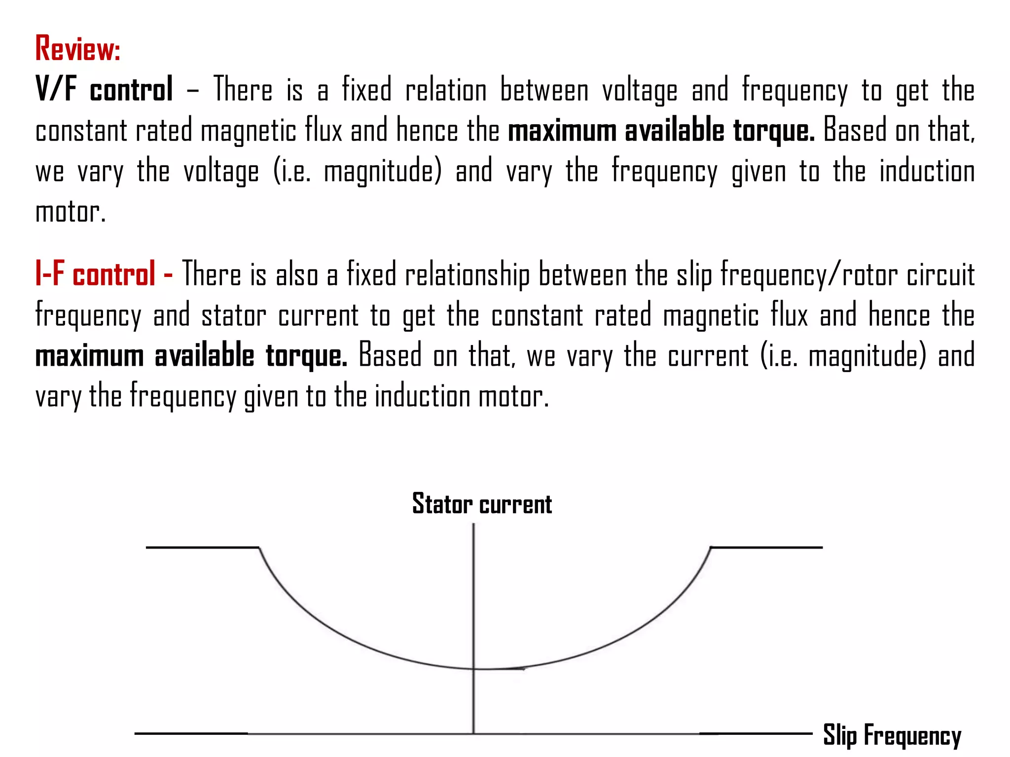
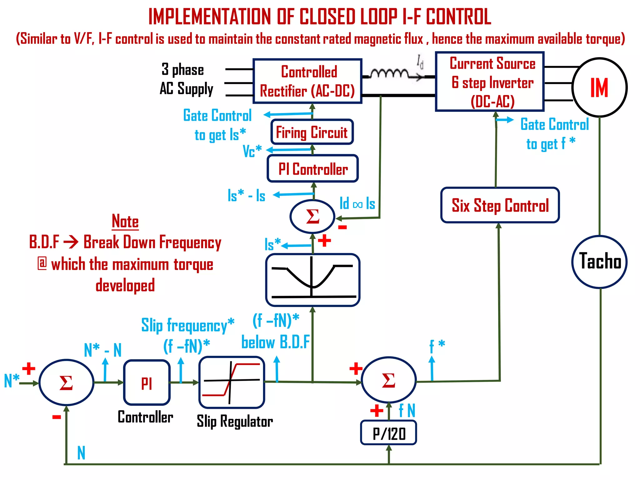
This document describes the Closed loop I-F control of Induction motor using six step Current Source Inverter (CSI).
For Explanation video- Please see my you tube channel - Future of EEE
This document presents information on variable frequency drives, including their control schemes and benefits. It discusses the components of an electric drive including the controller and AC motor. It describes scalar, vector, and direct torque control schemes and classifications of inverter drive topologies. The benefits of variable frequency drives are that they are economical, compact, save energy, require low maintenance, and have a wide speed range. Applications mentioned include use in oil and gas industry, refrigeration compressors, and railways.
Lesson 8- NodeMCU with Servo Motor
كورس تعلم شريحة NodeMCU وكيفيه استخدامها مع الحساسات.
Course Contents:
1- What is NodeMCU.
2- NodeMCU Instillation in Arduino IDE.
3- Simple Projects with NodeMCU (Sensors & Actuators)
4- NodeMCU with Communication protocols.
5- Connection NodeMCU with Wi-Fi.
6- Use NodeMCU as Clients & Server.
7- Different Platform uses with IOT application.
Simulation of Direct Torque Control of Induction motor using Space Vector Mo...IJMER
This document presents a simulation of direct torque control (DTC) of an induction motor using space vector modulation (SVM). It begins with an introduction to DTC and its advantages over field oriented control. It then describes the induction motor model and equations used in the simulation. The paper explains the DTC-SVM scheme, including flux and torque estimation, hysteresis controllers, voltage vector selection, and the simulation developed in MATLAB. The results show uniform torque production with reduced ripple compared to without DTC control. In conclusion, DTC-SVM provides improved dynamic performance over conventional DTC.
The document discusses basics of motor drives including variable frequency drives (VFDs). It explains that VFDs control AC motor speed by varying the frequency of the AC voltage supplied to the motor using electronic devices. The speed of an AC induction motor depends on the electrical frequency and number of poles. VFDs allow motors to operate at variable speeds by adjusting the frequency while maintaining constant voltage-to-frequency ratio to ensure full torque at all speeds.
An Electrical braking for all three phase electric motors , removes unnecessary use of mechanical brake lining or mechanical brake units , works with the concept of DC injection braking , also a braking for better safety , application in circular saws , grinding machines, centrifuges, vibrator motors
The document discusses control philosophies for various processes in wire rod production. It describes how a shear controls cutting of the wire rod head and tail by sensing the rod's position using sensors. It also explains how a looper forms loops of the rod between mill stands to maintain tension-free rolling using automatic loop control. It discusses detecting production faults if the rod takes too long between stands or other issues are observed. Finally, it summarizes how a snap shear cuts the rod if a cobble occurs and diverts the material to a cobble shear.
This document presents information on fly-by-wire flight control systems. It introduces fly-by-wire as a computer-based system that replaces mechanical flight controls with electronic signals transmitted via wires. This helps address issues with traditional mechanical systems like high weight and complexity. The document discusses the problem with existing control systems, effects of those problems, and how fly-by-wire solves them by providing advantages like increased stability, weight reduction, and easier maintenance.
A variable frequency drive (VFD) controls the speed of AC motors by adjusting both the voltage and frequency supplied to the motor. This allows for continuous speed control as opposed to discrete speeds from gearboxes. VFDs improve efficiency by matching the motor speed to the required process demands. They provide benefits like energy savings, improved power factor, soft starting and stopping of motors, and elimination of mechanical drive components. The document then discusses different types of motor loads and applications that can benefit from VFDs before explaining how pulse width modulation VFDs work by converting AC power to DC, and then back to AC with a controlled frequency.
The document summarizes research on using space vector modulation (SVM) for speed control of an induction motor driven by a three-phase inverter. It compares SVM to sine triangle pulse width modulation (SPWM) and finds that SVM provides better harmonic performance, higher DC bus utilization, and a more sinusoidal output voltage. The document simulates v/f control of an induction motor using SVM for both open-loop and closed-loop speed control systems. It is observed that the induction motor's performance is improved with SVM compared to SPWM modulation.
Three phase-induction-motor(eee499.blospot.com)slmnsvn
This presentation discusses speed control methods for three-phase induction motors, focusing on voltage source inverters (VSI) with pulse width modulation (PWM). Maintaining a constant ratio of output voltage to frequency (V/f) is identified as the best method, as it keeps the motor flux constant at all speeds. The project uses a PWM chip and isolated driver circuit to generate switching signals to control a three-leg VSI driving an induction motor. Measurements show the V/f ratio remains constant as the output frequency varies from 30Hz to 85Hz, demonstrating effective speed control of the induction motor.
The document provides information on AC drives from CG Drives, including their advantages, basic principles of operation, operating modes, braking types, and models. It discusses constant torque and variable torque loads, open loop V/F and vector control modes, closed loop vector control using feedback, and dynamic, DC injection, and regenerative braking methods. It also introduces the CG Drive-SK and CG Drive-SG product lines, specifying their features, connections, dimensions, and optional additions.
This document discusses variable voltage variable frequency (VVVF) drives. It begins with an introduction that explains how induction motors were previously only used for constant speed applications but advances in power transistors now allow for variable speed control. It then describes the operating principle of VVVF drives in controlling AC motor speed and torque by varying motor input frequency and voltage. The document outlines the key components of a VVVF drive system and explains the pulse width modulation technique used for voltage-frequency control. It concludes by listing some common applications and advantages of VVVF drives along with some drawbacks.
This document presents a simulation-based V/F speed control method for a three-phase induction motor. It discusses various speed control methods for induction motors and explains why constant V/F control is commonly used. It describes modeling a PWM inverter in Simulink to generate PWM pulses that are fed to a three-phase induction motor model. Simulation results show that open-loop V/F control can maintain constant torque over various rotor speeds by varying the voltage proportionally to frequency. Microcontrollers are discussed as a way to implement complex closed-loop speed control techniques. The document evaluates the simulation of open-loop V/F control for rated, above rated, and below rated motor speeds.
This document discusses variable voltage and variable frequency drives (VVVFD). It begins with an introduction that defines a VVVFD as a system that controls the rotational speed of an AC motor by controlling the frequency of the electrical power supplied. It then discusses operating principles such as how motor speed is determined by supply frequency. The document also describes the components of a VVVFD system including the controller and operation, noting it initially applies low frequency and voltage to avoid high inrush current. In conclusion, it states AC drives like VVVFDs are replacing DC motors in some applications due to advantages like automatic control.
This document summarizes a research paper that models, simulates, and analyzes the performance of a variable frequency drive (VFD) for speed control of an induction motor. The summary is:
1) A VFD controls the speed of an induction motor by varying the frequency of the applied AC voltage using pulse width modulation. This allows variable motor speed control needed in some industrial applications.
2) The paper models the key components of a VFD - the rectifier, DC bus, and inverter - and models the induction motor in a dq reference frame.
3) Simulation results in Matlab/Simulink successfully demonstrate speed control of the induction motor from zero to nominal speed by varying the drive
1) A servo is a feedback control system that controls the position or motion of a mechanical system. It receives an input signal and uses feedback to control velocity and position.
2) An electrical servo system relies on electrical energy and feedback to provide fast, accurate, and remote control. It has an error detector, amplifier, and error corrector to match the controlled variable to a reference signal.
3) A DC servo motor uses separate power sources for the field and armature windings. It can be field controlled, where the field is controlled by feedback, or armature controlled, where the armature is controlled by feedback. Field control provides slower response while armature control provides faster response.
Squirrel cage induction motor scalar control constant V/F analysisTELKOMNIKA JOURNAL
In constant V/f control technique it is assume that the stator resistance and leakage inductance drops are negligible, especially at high speed and small load. In other words, the back emf is comparatively large at high speed and hence these voltage drops can be neglected. By maintaining constant V/f, constant Eg/f and hence constant air-gap flux is assumed. This assumption is however invalid at low speeds since a significant voltage drop appears across the stator impedance. The terminal voltage, V no longer approximates ag. By using MATLAB Simulink, the open-loop constant V/f is simulated. It is shown that the performance of the drive deteriorates at low speeds. The improvement in the performance by applying voltage boost is shown and discussed.
Implementation of ac induction motor control using constant vhz principle and...eSAT Journals
Abstract
This paper presents the hardware implementation of V/f control of induction motor using sine wave PWM method. Because of its
simplicity, the V/F control also called as the scalar control, is the most widely used speed control method in the industrial
applications. In this method the ratio between stator voltage to frequency is maintained constant so that the stator flux is
maintained constant. As the stator flux is maintained constant, the torque developed by the motor depends only on the slip speed
and is independent of the supply frequency. Thus we can control the speed and torque of induction motor by simply controlling the
slip speed of induction motor. The complete control is achieved with the help of TMS320F28027 Development Board. One of the
basic requirements of this scheme is the PWM inverter. The gating signals are generated using sine wave PWM technique.
Implementation issues such as PWM signal generation, ramp control, v/f control, inverter design are discussed. The results are
discussed based on the various waveforms.
KeyWords: v/f control, Induction motor, PWM, and Scalar control
1) A servo motor is a motor that is part of a servomechanism and is typically paired with an encoder to provide position and speed feedback. It requires a controller to compare the feedback to a reference signal and correct any errors.
2) There are two main types of servo motors - AC and DC. DC servo motors are preferred for high power applications due to their higher efficiency. DC servo motors have field and armature windings that can be controlled separately to provide precise torque control.
3) A DC servo motor works by using an amplified error signal from a position sensor to control either the field or armature winding, depending on the application. This allows the motor's torque to be controlled to minimize
This document discusses motor converter control for a 6000 HP IGBT-based locomotive. It includes a block diagram of the motor control system and describes functions like torque reference generation, motor torque control, weight transfer between bogies, axle force correction, line current control, and induction motor torque control using vector control. Wheel slip slide detection uses the rate of change of motor speeds and difference between motor and vehicle speeds. Wheel slip control reduces torque after detection, and a limiter prevents excess speed difference. Start stop jerk is limited for individual inverters. SPWM modulation generates pulse patterns from reference and carrier waves.
Speed control of 3 phase induction motormpsrekha83
This document discusses four main methods for controlling the speed of a 3-phase induction motor: 1) by changing the applied voltage, 2) by changing the applied frequency, 3) using constant V/F control, and 4) by changing the number of stator poles. Changing the applied voltage is the simplest but requires large voltage changes for small speed adjustments. Changing frequency works but induction motors are typically powered by dedicated generators. Constant V/F control maintains constant flux to allow smooth speed control and soft starts. Changing stator poles allows different synchronous speeds by using multiple windings.
1. There are three types of DC motor connections: series, shunt, and compound. DC motors are commonly used in factories due to their high starting torque and ability to operate at various speeds in both directions.
2. There are three main methods to control DC motor speed: field control, armature control, and input voltage control. Field control varies the field resistance to reduce flux and increase speed. Armature control uses a variable resistance in series with the armature to adjust motor speed over a large range.
3. The Ward-Leonard system uses a generator and DC motor coupled together, with an electronic amplifier controlling the generator field current to vary the motor input voltage and thereby the speed. It provides
Unit v conventional and solid state speed control of ac drivesDr SOUNDIRARAJ N
This document discusses various methods for controlling the speed of AC induction motors, including stator-side control by varying voltage or frequency, and rotor-side control using cascade control, adding rotor resistance, or slip power recovery schemes. Stator-side control involves changing the stator voltage using autotransformers or resistors, or changing the frequency which varies the synchronous speed. Rotor-side control techniques include cascade control using two motors, adding external resistance in the rotor circuit, or recovering slip power using Kramer or Scherbius systems.
Study of Different Types of Inverters and FFT Analysis of Output of SPWM Inve...RSIS International
This paper briefly discusses various types of inverters
and the output waveforms of square wave inverter and SPWM
inverter. FFT analysis is performed on the outputs obtained for
SPWM inverter. The variation in THD by varying the
Modulating Index and Carrier Frequency is also included
This document discusses a project to simulate an SVPWM inverter to reduce total harmonic distortion and control the speed of a 3-phase induction motor. The objectives are to reduce THD and achieve variable frequency speed control of the induction motor using space vector modulation. The system takes a speed setpoint as input, calculates the slip frequency, and uses constant V/f control to determine the required voltage output. Simulation results will compare THD, output voltage, and switching losses of SVPWM to conventional methods. Controllers like PI, PD and PID will also be compared for better speed response of the induction motor.
Equivalent Circuit, Phasor Diagram, Power Factor Control , V & Inverted V Cur...Citharthan Durairaj
This video describes the Equivalent Circuit, Phasor Diagram, Power Factor Control , V & Inverted V Curve of Synchronous Motor
For video please click the below link
https://www.youtube.com/watch?v=GdEAc_IHLbA&t=118s
This presentation describes the Voltage Source Inverter (VSI) - Six Step Switching - Pole voltages and its control - Frequency control of line voltages
More Related Content
Similar to Closed Loop I-F control using six step current source inverter
A variable frequency drive (VFD) controls the speed of AC motors by adjusting both the voltage and frequency supplied to the motor. This allows for continuous speed control as opposed to discrete speeds from gearboxes. VFDs improve efficiency by matching the motor speed to the required process demands. They provide benefits like energy savings, improved power factor, soft starting and stopping of motors, and elimination of mechanical drive components. The document then discusses different types of motor loads and applications that can benefit from VFDs before explaining how pulse width modulation VFDs work by converting AC power to DC, and then back to AC with a controlled frequency.
The document summarizes research on using space vector modulation (SVM) for speed control of an induction motor driven by a three-phase inverter. It compares SVM to sine triangle pulse width modulation (SPWM) and finds that SVM provides better harmonic performance, higher DC bus utilization, and a more sinusoidal output voltage. The document simulates v/f control of an induction motor using SVM for both open-loop and closed-loop speed control systems. It is observed that the induction motor's performance is improved with SVM compared to SPWM modulation.
Three phase-induction-motor(eee499.blospot.com)slmnsvn
This presentation discusses speed control methods for three-phase induction motors, focusing on voltage source inverters (VSI) with pulse width modulation (PWM). Maintaining a constant ratio of output voltage to frequency (V/f) is identified as the best method, as it keeps the motor flux constant at all speeds. The project uses a PWM chip and isolated driver circuit to generate switching signals to control a three-leg VSI driving an induction motor. Measurements show the V/f ratio remains constant as the output frequency varies from 30Hz to 85Hz, demonstrating effective speed control of the induction motor.
The document provides information on AC drives from CG Drives, including their advantages, basic principles of operation, operating modes, braking types, and models. It discusses constant torque and variable torque loads, open loop V/F and vector control modes, closed loop vector control using feedback, and dynamic, DC injection, and regenerative braking methods. It also introduces the CG Drive-SK and CG Drive-SG product lines, specifying their features, connections, dimensions, and optional additions.
This document discusses variable voltage variable frequency (VVVF) drives. It begins with an introduction that explains how induction motors were previously only used for constant speed applications but advances in power transistors now allow for variable speed control. It then describes the operating principle of VVVF drives in controlling AC motor speed and torque by varying motor input frequency and voltage. The document outlines the key components of a VVVF drive system and explains the pulse width modulation technique used for voltage-frequency control. It concludes by listing some common applications and advantages of VVVF drives along with some drawbacks.
This document presents a simulation-based V/F speed control method for a three-phase induction motor. It discusses various speed control methods for induction motors and explains why constant V/F control is commonly used. It describes modeling a PWM inverter in Simulink to generate PWM pulses that are fed to a three-phase induction motor model. Simulation results show that open-loop V/F control can maintain constant torque over various rotor speeds by varying the voltage proportionally to frequency. Microcontrollers are discussed as a way to implement complex closed-loop speed control techniques. The document evaluates the simulation of open-loop V/F control for rated, above rated, and below rated motor speeds.
This document discusses variable voltage and variable frequency drives (VVVFD). It begins with an introduction that defines a VVVFD as a system that controls the rotational speed of an AC motor by controlling the frequency of the electrical power supplied. It then discusses operating principles such as how motor speed is determined by supply frequency. The document also describes the components of a VVVFD system including the controller and operation, noting it initially applies low frequency and voltage to avoid high inrush current. In conclusion, it states AC drives like VVVFDs are replacing DC motors in some applications due to advantages like automatic control.
This document summarizes a research paper that models, simulates, and analyzes the performance of a variable frequency drive (VFD) for speed control of an induction motor. The summary is:
1) A VFD controls the speed of an induction motor by varying the frequency of the applied AC voltage using pulse width modulation. This allows variable motor speed control needed in some industrial applications.
2) The paper models the key components of a VFD - the rectifier, DC bus, and inverter - and models the induction motor in a dq reference frame.
3) Simulation results in Matlab/Simulink successfully demonstrate speed control of the induction motor from zero to nominal speed by varying the drive
1) A servo is a feedback control system that controls the position or motion of a mechanical system. It receives an input signal and uses feedback to control velocity and position.
2) An electrical servo system relies on electrical energy and feedback to provide fast, accurate, and remote control. It has an error detector, amplifier, and error corrector to match the controlled variable to a reference signal.
3) A DC servo motor uses separate power sources for the field and armature windings. It can be field controlled, where the field is controlled by feedback, or armature controlled, where the armature is controlled by feedback. Field control provides slower response while armature control provides faster response.
Squirrel cage induction motor scalar control constant V/F analysisTELKOMNIKA JOURNAL
In constant V/f control technique it is assume that the stator resistance and leakage inductance drops are negligible, especially at high speed and small load. In other words, the back emf is comparatively large at high speed and hence these voltage drops can be neglected. By maintaining constant V/f, constant Eg/f and hence constant air-gap flux is assumed. This assumption is however invalid at low speeds since a significant voltage drop appears across the stator impedance. The terminal voltage, V no longer approximates ag. By using MATLAB Simulink, the open-loop constant V/f is simulated. It is shown that the performance of the drive deteriorates at low speeds. The improvement in the performance by applying voltage boost is shown and discussed.
Implementation of ac induction motor control using constant vhz principle and...eSAT Journals
Abstract
This paper presents the hardware implementation of V/f control of induction motor using sine wave PWM method. Because of its
simplicity, the V/F control also called as the scalar control, is the most widely used speed control method in the industrial
applications. In this method the ratio between stator voltage to frequency is maintained constant so that the stator flux is
maintained constant. As the stator flux is maintained constant, the torque developed by the motor depends only on the slip speed
and is independent of the supply frequency. Thus we can control the speed and torque of induction motor by simply controlling the
slip speed of induction motor. The complete control is achieved with the help of TMS320F28027 Development Board. One of the
basic requirements of this scheme is the PWM inverter. The gating signals are generated using sine wave PWM technique.
Implementation issues such as PWM signal generation, ramp control, v/f control, inverter design are discussed. The results are
discussed based on the various waveforms.
KeyWords: v/f control, Induction motor, PWM, and Scalar control
1) A servo motor is a motor that is part of a servomechanism and is typically paired with an encoder to provide position and speed feedback. It requires a controller to compare the feedback to a reference signal and correct any errors.
2) There are two main types of servo motors - AC and DC. DC servo motors are preferred for high power applications due to their higher efficiency. DC servo motors have field and armature windings that can be controlled separately to provide precise torque control.
3) A DC servo motor works by using an amplified error signal from a position sensor to control either the field or armature winding, depending on the application. This allows the motor's torque to be controlled to minimize
This document discusses motor converter control for a 6000 HP IGBT-based locomotive. It includes a block diagram of the motor control system and describes functions like torque reference generation, motor torque control, weight transfer between bogies, axle force correction, line current control, and induction motor torque control using vector control. Wheel slip slide detection uses the rate of change of motor speeds and difference between motor and vehicle speeds. Wheel slip control reduces torque after detection, and a limiter prevents excess speed difference. Start stop jerk is limited for individual inverters. SPWM modulation generates pulse patterns from reference and carrier waves.
Speed control of 3 phase induction motormpsrekha83
This document discusses four main methods for controlling the speed of a 3-phase induction motor: 1) by changing the applied voltage, 2) by changing the applied frequency, 3) using constant V/F control, and 4) by changing the number of stator poles. Changing the applied voltage is the simplest but requires large voltage changes for small speed adjustments. Changing frequency works but induction motors are typically powered by dedicated generators. Constant V/F control maintains constant flux to allow smooth speed control and soft starts. Changing stator poles allows different synchronous speeds by using multiple windings.
1. There are three types of DC motor connections: series, shunt, and compound. DC motors are commonly used in factories due to their high starting torque and ability to operate at various speeds in both directions.
2. There are three main methods to control DC motor speed: field control, armature control, and input voltage control. Field control varies the field resistance to reduce flux and increase speed. Armature control uses a variable resistance in series with the armature to adjust motor speed over a large range.
3. The Ward-Leonard system uses a generator and DC motor coupled together, with an electronic amplifier controlling the generator field current to vary the motor input voltage and thereby the speed. It provides
Unit v conventional and solid state speed control of ac drivesDr SOUNDIRARAJ N
This document discusses various methods for controlling the speed of AC induction motors, including stator-side control by varying voltage or frequency, and rotor-side control using cascade control, adding rotor resistance, or slip power recovery schemes. Stator-side control involves changing the stator voltage using autotransformers or resistors, or changing the frequency which varies the synchronous speed. Rotor-side control techniques include cascade control using two motors, adding external resistance in the rotor circuit, or recovering slip power using Kramer or Scherbius systems.
Study of Different Types of Inverters and FFT Analysis of Output of SPWM Inve...RSIS International
This paper briefly discusses various types of inverters
and the output waveforms of square wave inverter and SPWM
inverter. FFT analysis is performed on the outputs obtained for
SPWM inverter. The variation in THD by varying the
Modulating Index and Carrier Frequency is also included
This document discusses a project to simulate an SVPWM inverter to reduce total harmonic distortion and control the speed of a 3-phase induction motor. The objectives are to reduce THD and achieve variable frequency speed control of the induction motor using space vector modulation. The system takes a speed setpoint as input, calculates the slip frequency, and uses constant V/f control to determine the required voltage output. Simulation results will compare THD, output voltage, and switching losses of SVPWM to conventional methods. Controllers like PI, PD and PID will also be compared for better speed response of the induction motor.
Similar to Closed Loop I-F control using six step current source inverter (20)
Equivalent Circuit, Phasor Diagram, Power Factor Control , V & Inverted V Cur...Citharthan Durairaj
This video describes the Equivalent Circuit, Phasor Diagram, Power Factor Control , V & Inverted V Curve of Synchronous Motor
For video please click the below link
https://www.youtube.com/watch?v=GdEAc_IHLbA&t=118s
This presentation describes the Voltage Source Inverter (VSI) - Six Step Switching - Pole voltages and its control - Frequency control of line voltages
V/F control of Induction Motor - Variable voltage and Variable frequencyCitharthan Durairaj
This presentation describes Principle of Variable voltage and Variable frequency- the open loop & closed loop Voltage/Frequency (V/F) control of Induction motor with torque speed characteristics -
This presentation describes the
Line Voltage Control - Torque Speed Characteristics - Methods -Advantages - Disadvantages - Applications of Voltage control
This presentation describes the per-phase equivalent circuit of induction motor - Power flow diagram - Ratio of air gap power, rotor copper loss and mechanical power developed.
Torque speed characteristics of Squirrel cage & Slip ring induction motorsCitharthan Durairaj
This video describes the Torque - Slip / Torque- Speed Characteristics of three phase squirrel cage induction motor and slip ring induction motor- also describes the Condition for the maximum torque - Pullout torque and Pullout torque equation
This presentation describes the Principle of Operation - Squirrel cage Induction motor
Classification of Induction motors
Rotating Magnetic flux- Relative Motion - Faradays law- Lenz law
This video describes the monitoring of sensor values/ random values using blynk app and FRED IoT
Steps to be done in Blynk App & Steps to be done in FRED IoT
This Presentation describes the
Introduction to IoT - What is IoT ?
An Example - Home automation - Hardware and Software
If you have questions, please don't hesitate to ask in the comment section.
Pls like, share and subscribe. Thank you!
#FutureofEEE
There are three main types of stepper motors: variable reluctance, permanent magnet, and hybrid. Variable reluctance stepper motors use changes in magnetic reluctance to rotate and can be single or multi-stack. They provide high torque but have torque ripple issues. Permanent magnet stepper motors use permanent magnets on the rotor and have bipolar drive circuits. They can achieve a 45 degree step angle through alternate single and two phase excitation. Hybrid stepper motors combine features of variable reluctance and permanent magnet motors, with a 4 pole stator and 5 pole rotor construction. Each motor type has advantages and disadvantages related to torque, torque ripple, and drive circuit complexity.
1) The document discusses permanent magnet brushless DC (PMBLDC) motors and their control. It explains that the desired current waveform for each phase must be estimated based on the instantaneous rotor position to satisfy the maximum torque at minimum current principle.
2) The desired current is provided to the phases through driver circuits containing six transistors, which are switched on based on whether the desired current is positive or negative.
3) Rotor position is typically sensed using three Hall sensors spaced 120 degrees apart, though sensorless control is also possible using back EMF measurements. Control circuit design and operation are also briefly outlined.
1) For alternators to operate in parallel, they must be synchronized by having equal line voltage, frequency, phase sequence, phase angle, and waveform.
2) When alternators are synchronized and operating in parallel with no load, a circulating current will flow if their speeds or excitations differ slightly.
3) This circulating current acts to resynchronize the alternators by speeding up the slower one and slowing the faster one through their functioning as motor and generator respectively, until steady state is reached with no circulating current.
Introduction- e - waste – definition - sources of e-waste– hazardous substances in e-waste - effects of e-waste on environment and human health- need for e-waste management– e-waste handling rules - waste minimization techniques for managing e-waste – recycling of e-waste - disposal treatment methods of e- waste – mechanism of extraction of precious metal from leaching solution-global Scenario of E-waste – E-waste in India- case studies.
Advanced control scheme of doubly fed induction generator for wind turbine us...IJECEIAES
This paper describes a speed control device for generating electrical energy on an electricity network based on the doubly fed induction generator (DFIG) used for wind power conversion systems. At first, a double-fed induction generator model was constructed. A control law is formulated to govern the flow of energy between the stator of a DFIG and the energy network using three types of controllers: proportional integral (PI), sliding mode controller (SMC) and second order sliding mode controller (SOSMC). Their different results in terms of power reference tracking, reaction to unexpected speed fluctuations, sensitivity to perturbations, and resilience against machine parameter alterations are compared. MATLAB/Simulink was used to conduct the simulations for the preceding study. Multiple simulations have shown very satisfying results, and the investigations demonstrate the efficacy and power-enhancing capabilities of the suggested control system.
Harnessing WebAssembly for Real-time Stateless Streaming PipelinesChristina Lin
Traditionally, dealing with real-time data pipelines has involved significant overhead, even for straightforward tasks like data transformation or masking. However, in this talk, we’ll venture into the dynamic realm of WebAssembly (WASM) and discover how it can revolutionize the creation of stateless streaming pipelines within a Kafka (Redpanda) broker. These pipelines are adept at managing low-latency, high-data-volume scenarios.
Literature Review Basics and Understanding Reference Management.pptxDr Ramhari Poudyal
Three-day training on academic research focuses on analytical tools at United Technical College, supported by the University Grant Commission, Nepal. 24-26 May 2024
KuberTENes Birthday Bash Guadalajara - K8sGPT first impressionsVictor Morales
K8sGPT is a tool that analyzes and diagnoses Kubernetes clusters. This presentation was used to share the requirements and dependencies to deploy K8sGPT in a local environment.
HEAP SORT ILLUSTRATED WITH HEAPIFY, BUILD HEAP FOR DYNAMIC ARRAYS.
Heap sort is a comparison-based sorting technique based on Binary Heap data structure. It is similar to the selection sort where we first find the minimum element and place the minimum element at the beginning. Repeat the same process for the remaining elements.
6th International Conference on Machine Learning & Applications (CMLA 2024)ClaraZara1
6th International Conference on Machine Learning & Applications (CMLA 2024) will provide an excellent international forum for sharing knowledge and results in theory, methodology and applications of on Machine Learning & Applications.
Low power architecture of logic gates using adiabatic techniquesnooriasukmaningtyas
The growing significance of portable systems to limit power consumption in ultra-large-scale-integration chips of very high density, has recently led to rapid and inventive progresses in low-power design. The most effective technique is adiabatic logic circuit design in energy-efficient hardware. This paper presents two adiabatic approaches for the design of low power circuits, modified positive feedback adiabatic logic (modified PFAL) and the other is direct current diode based positive feedback adiabatic logic (DC-DB PFAL). Logic gates are the preliminary components in any digital circuit design. By improving the performance of basic gates, one can improvise the whole system performance. In this paper proposed circuit design of the low power architecture of OR/NOR, AND/NAND, and XOR/XNOR gates are presented using the said approaches and their results are analyzed for powerdissipation, delay, power-delay-product and rise time and compared with the other adiabatic techniques along with the conventional complementary metal oxide semiconductor (CMOS) designs reported in the literature. It has been found that the designs with DC-DB PFAL technique outperform with the percentage improvement of 65% for NOR gate and 7% for NAND gate and 34% for XNOR gate over the modified PFAL techniques at 10 MHz respectively.
Low power architecture of logic gates using adiabatic techniques
Closed Loop I-F control using six step current source inverter
1. SPEED CONTROL METHODS OF INDUCTION MOTOR
1) Line voltage control
2) Line frequency control
Variable frequency constant voltage
Voltage/Frequency control (V/F)
Voltage Source Inverter fed induction motor drive
Current Source Inverter fed induction motor drive
3) Rotor resistance control - used only in slip ring Induction motor
4) Slip power recovery scheme - used only in slip ring Induction motor
Six Step
PWM
I-F control
2. Review:
V/F control – There is a fixed relation between voltage and frequency to get the
constant rated magnetic flux and hence the maximum available torque. Based on that,
we vary the voltage (i.e. magnitude) and vary the frequency given to the induction
motor.
I-F control - There is also a fixed relationship between the slip frequency/rotor circuit
frequency and stator current to get the constant rated magnetic flux and hence the
maximum available torque. Based on that, we vary the current (i.e. magnitude) and
vary the frequency given to the induction motor.
Slip Frequency
Stator current
3. IMPLEMENTATION OF CLOSED LOOP I-F CONTROL
(Similar to V/F, I-F control is used to maintain the constant rated magnetic flux , hence the maximum available torque)
Controlled
Rectifier (AC-DC)
Current Source
6 step Inverter
(DC-AC)
3 phase
AC Supply IM
Tacho
ΣN* PI
N* - N
Controller Slip Regulator
(f –fN)*
below B.D.F
Σ
Slip frequency*
(f –fN)*
P/120
f N+
++
-
Σ
Is*
PI Controller
Firing Circuit
Id ∞ IsIs* - Is
Vc*
f *
Six Step Control
Note
B.D.F Break Down Frequency
@ which the maximum torque
developed
Gate Control
to get f *
Gate Control
to get Is*
N
+ -
4. 6 STEP CURRENT SOURCE INVERTER
DOWNLOAD
(PPT & PDF)
LINK IN THE DESCRIPTION