The document explains the equivalent circuit of a three-phase induction motor, likening it to a rotating transformer, and discusses the performance prediction based on stator and rotor circuits that operate at different frequencies. It details how to address issues related to slip, air gap power, rotor copper loss, and mechanical power, highlighting the relationships between these factors. Key points include the significance of torque-slip characteristics and efficiency improvements by minimizing slip and increasing starting torque in slip ring induction motors.
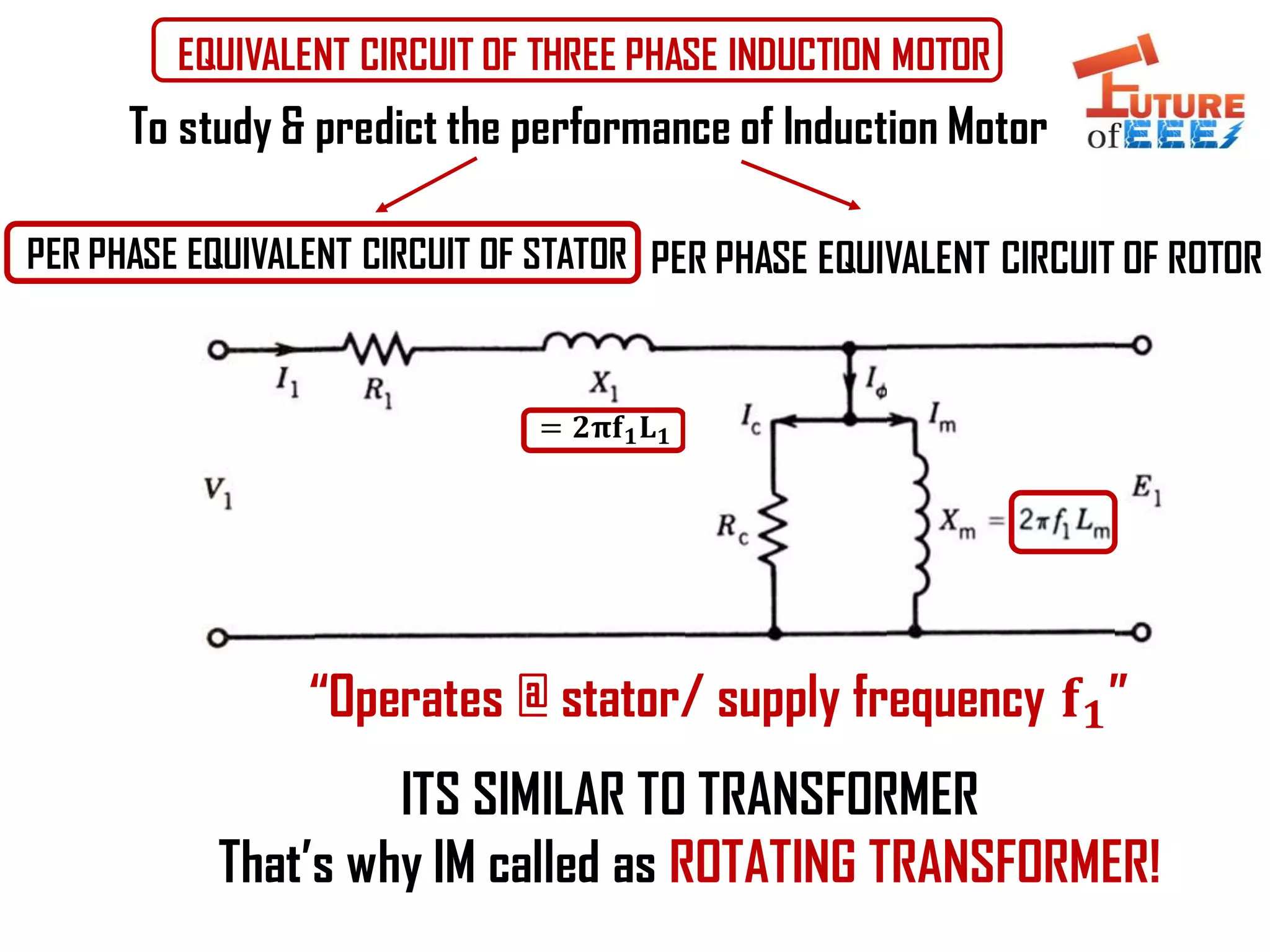
EQUIVALENT CIRCUIT OFTHREE PHASE INDUCTION MOTOR
PER PHASE EQUIVALENT CIRCUIT OF STATOR PER PHASE EQUIVALENT CIRCUIT OF ROTOR
To study & predict the performance of Induction Motor
ITS SIMILAR TO TRANSFORMER
That’s why IM called as ROTATING TRANSFORMER!
= 𝟐𝛑𝐟 𝟏 𝐋 𝟏
“Operates @ stator/ supply frequency 𝐟 𝟏”
2.
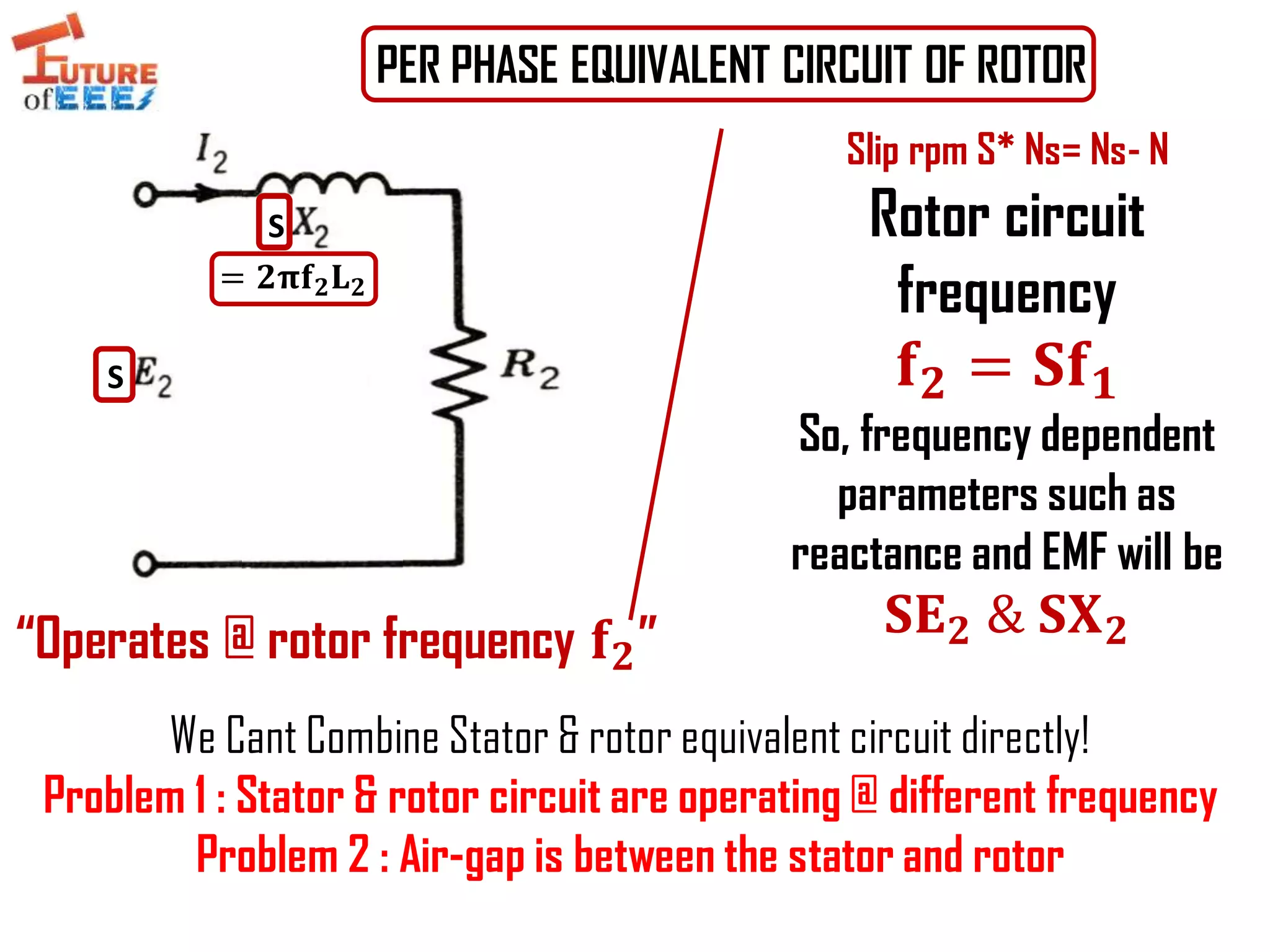
PER PHASE EQUIVALENTCIRCUIT OF ROTOR
Slip rpm S* Ns= Ns- N
Rotor circuit
frequency
𝐟 𝟐 = 𝐒𝐟 𝟏
So, frequency dependent
parameters such as
reactance and EMF will be
𝐒𝐄 𝟐 & 𝐒𝐗 𝟐
S
S
= 𝟐𝛑𝐟 𝟐 𝐋 𝟐
We Cant Combine Stator & rotor equivalent circuit directly!
Problem 1 : Stator & rotor circuit are operating @ different frequency
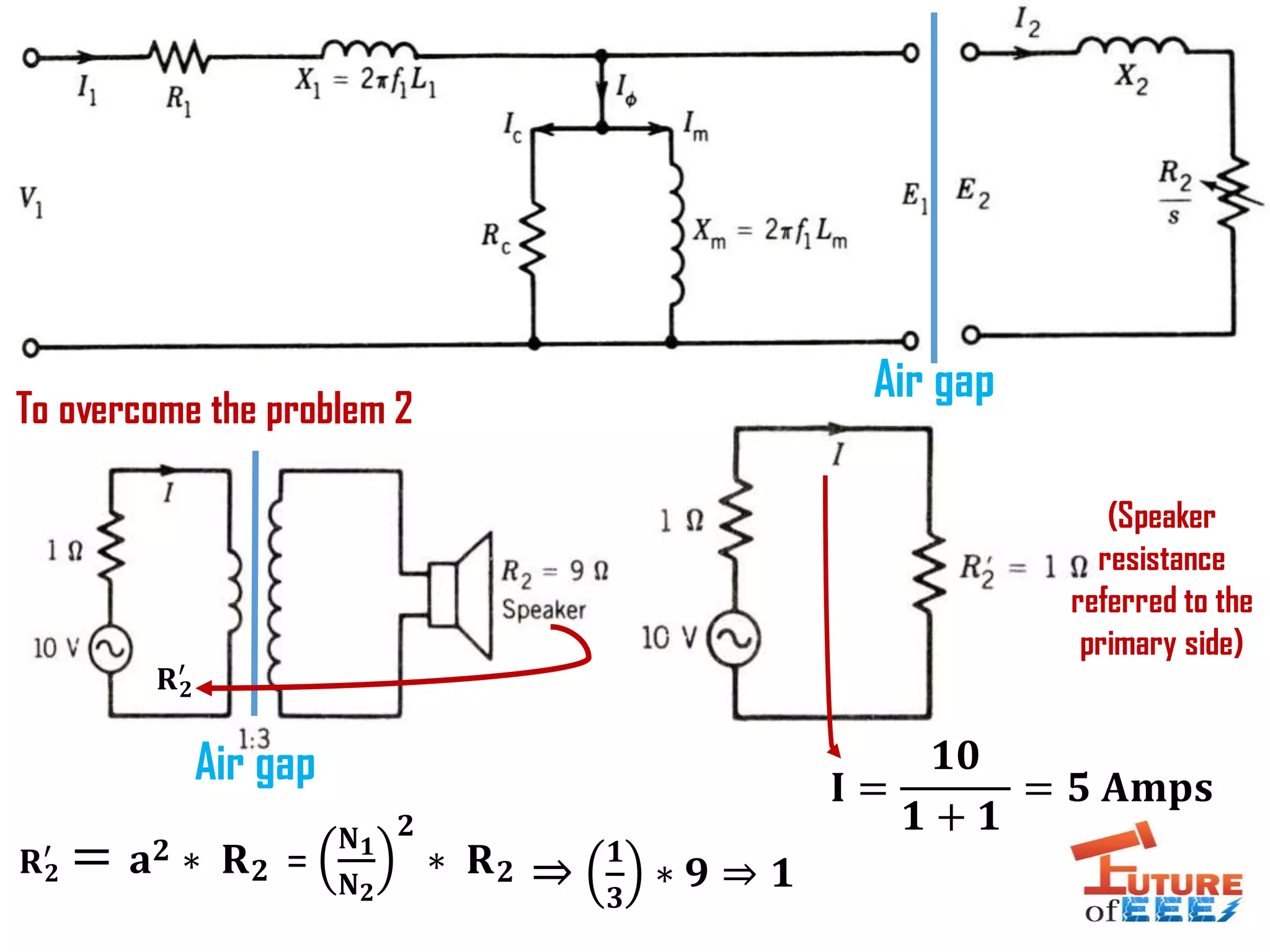
Problem 2 : Air-gap is between the stator and rotor
“Operates @ rotor frequency 𝐟 𝟐”
To overcome theproblem 2
(Speaker
resistance
referred to the
primary side)
Air gap
Air gap
𝐑 𝟐
′
= 𝐚 𝟐 ∗ 𝐑 𝟐
𝐈 =
𝟏𝟎
𝟏 + 𝟏
= 𝟓 𝐀𝐦𝐩𝐬
𝐑 𝟐
′
=
𝐍 𝟏
𝐍 𝟐
𝟐
∗ 𝐑 𝟐 ⇒
𝟏
𝟑
∗ 𝟗 ⇒ 𝟏
5.
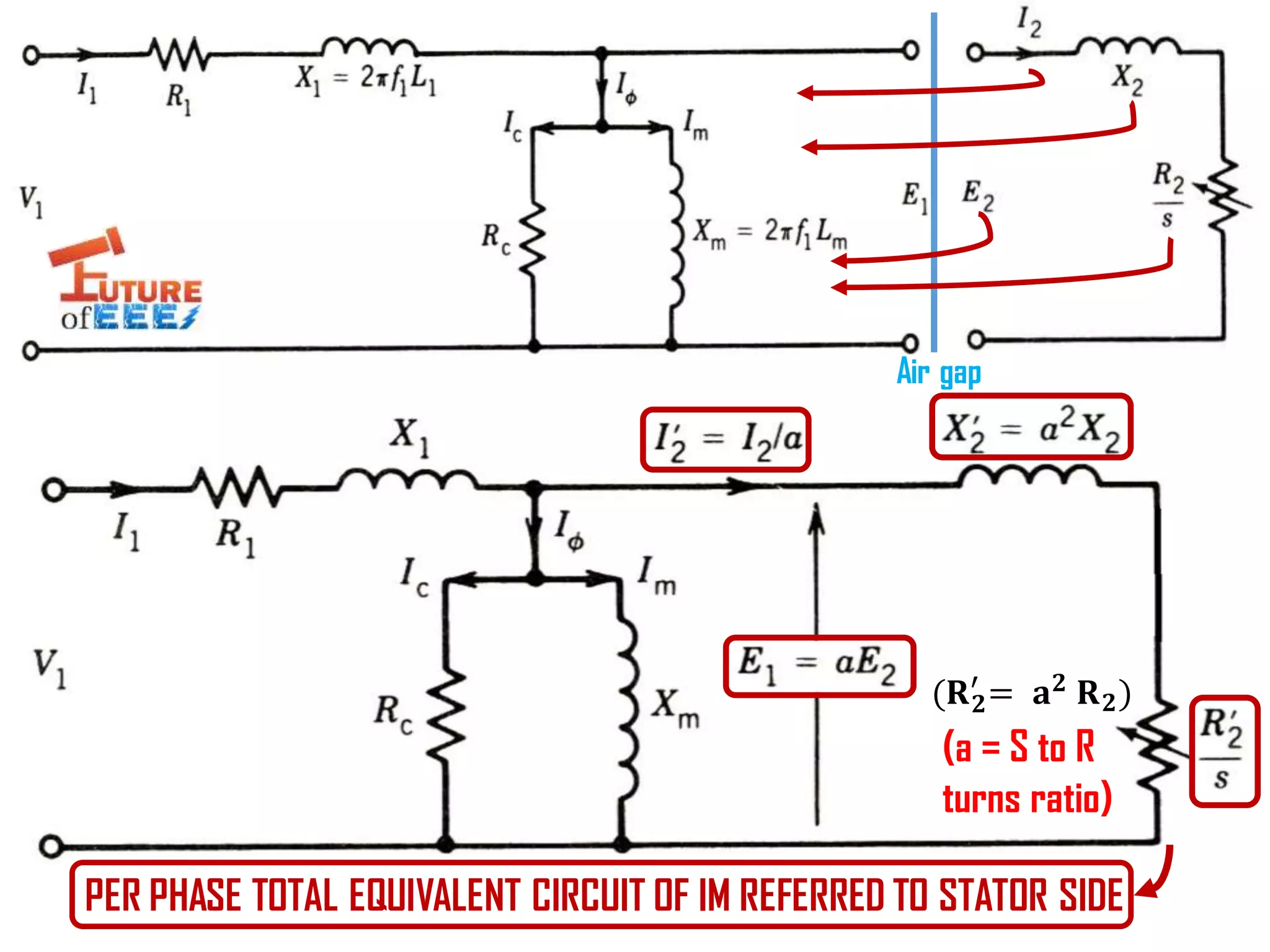
PER PHASE TOTALEQUIVALENT CIRCUIT OF IM REFERRED TO STATOR SIDE
Air gap
(a = S to R
turns ratio)
ሺ𝐑 𝟐
′
= 𝐚 𝟐 𝐑 𝟐)
6.
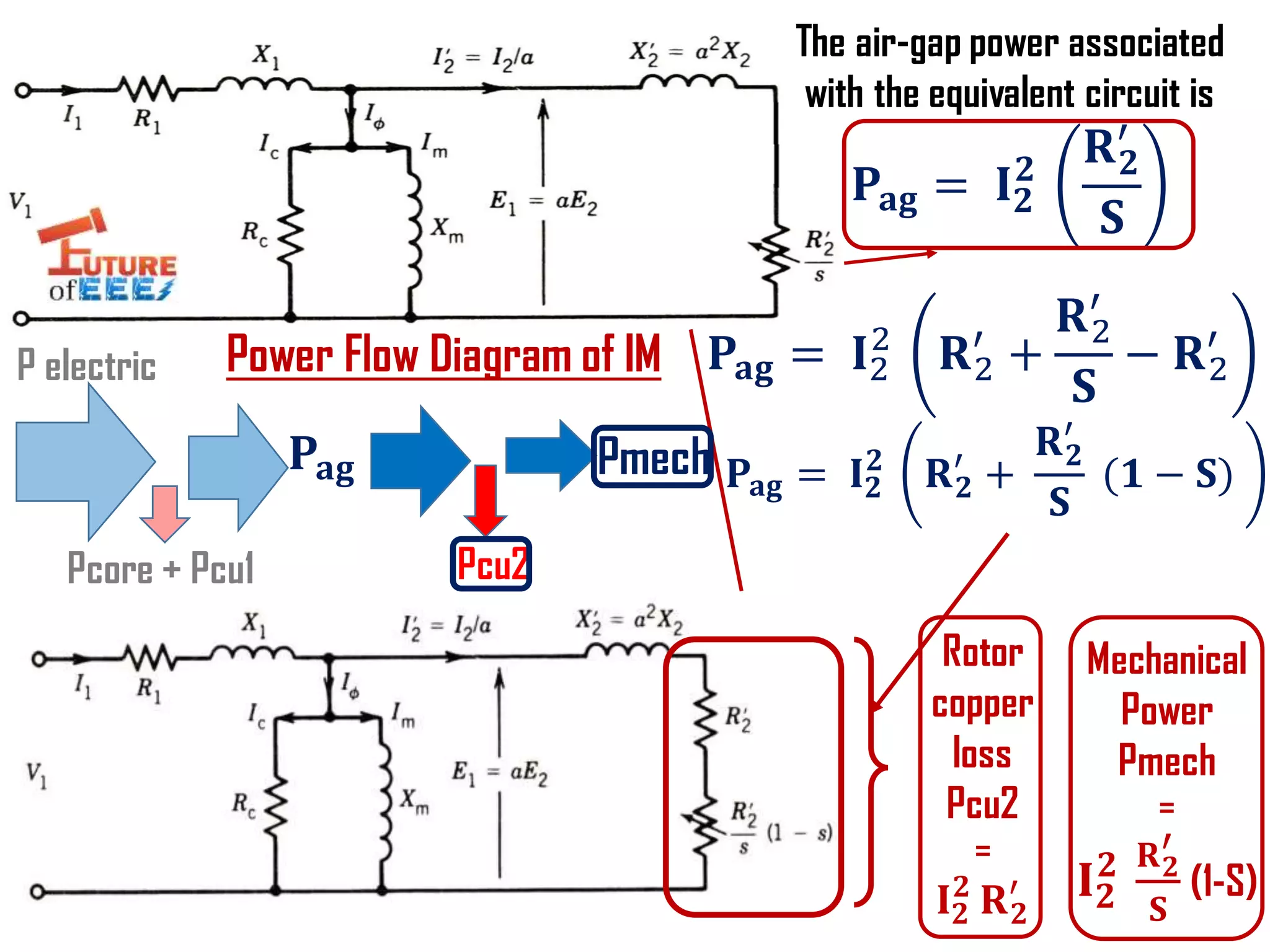
The air-gap powerassociated
with the equivalent circuit is
𝐏𝐚𝐠 = 𝐈 𝟐
𝟐
𝐑 𝟐
′
𝐒
𝐏𝐚𝐠 = 𝐈2
2
𝐑2
′
+
𝐑2
′
𝐒
− 𝐑2
′
𝐏𝐚𝐠 = 𝐈 𝟐
𝟐
𝐑 𝟐
′
+
𝐑 𝟐
′
𝐒
ሺ𝟏 − 𝐒)
Rotor
copper
loss
Pcu2
=
𝐈 𝟐
𝟐
𝐑 𝟐
′
Mechanical
Power
Pmech
=
𝐈 𝟐
𝟐 𝐑 𝟐
′
𝐒
(1-S)
Power Flow Diagram of IM
𝐏𝐚𝐠
Pcu2
Pmech
P electric
Pcore + Pcu1
7.
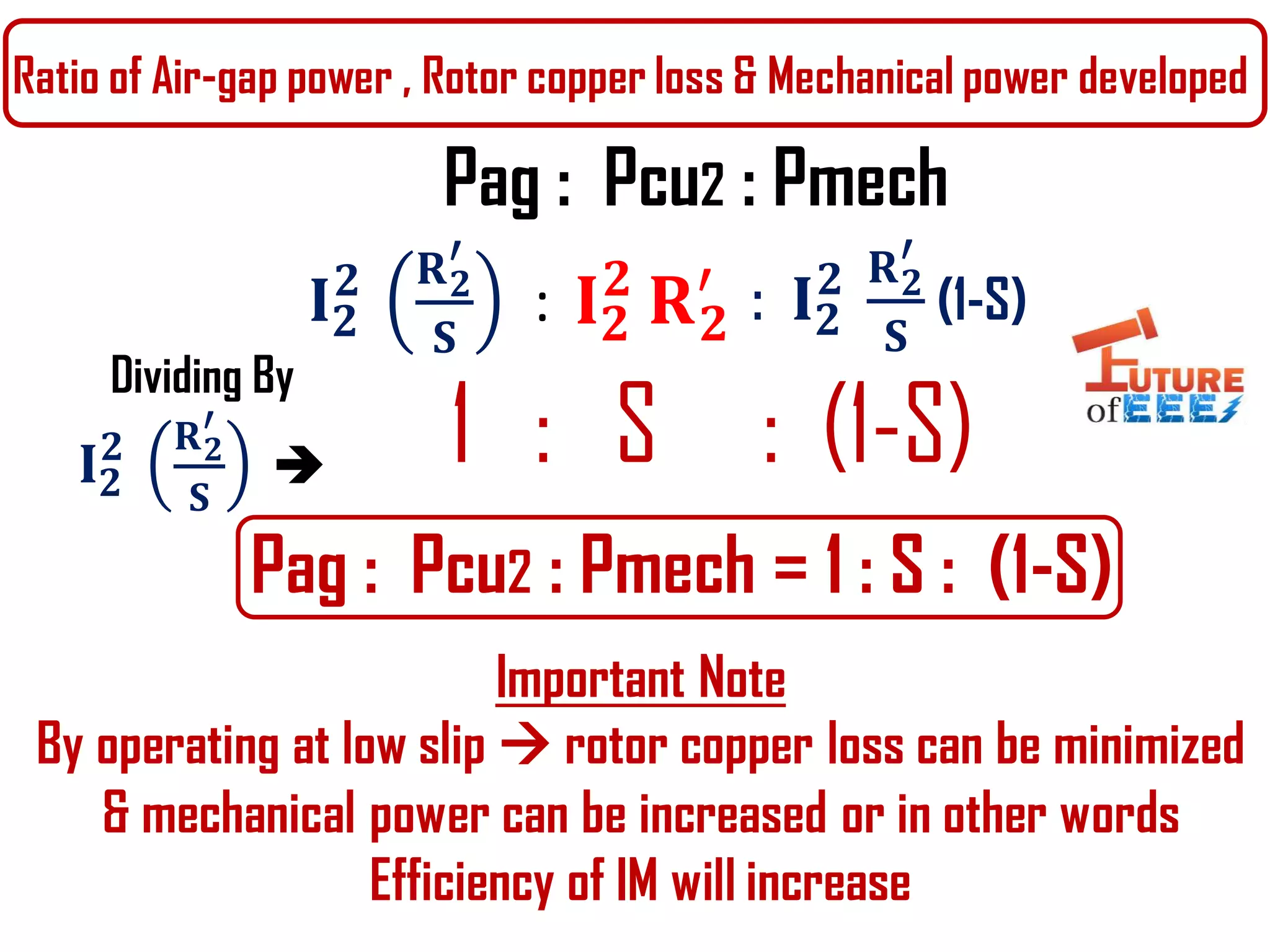
Ratio of Air-gappower , Rotor copper loss & Mechanical power developed
Pag : Pcu2 : Pmech = 1 : S : (1-S)
𝐈 𝟐
𝟐 𝐑 𝟐
′
𝐒
: 𝐈 𝟐
𝟐
𝐑 𝟐
′ : 𝐈 𝟐
𝟐 𝐑 𝟐
′
𝐒
(1-S)
Dividing By
𝐈 𝟐
𝟐 𝐑 𝟐
′
𝐒
1 : S : (1-S)
Pag : Pcu2 : Pmech
Important Note
By operating at low slip rotor copper loss can be minimized
& mechanical power can be increased or in other words
Efficiency of IM will increase
8.
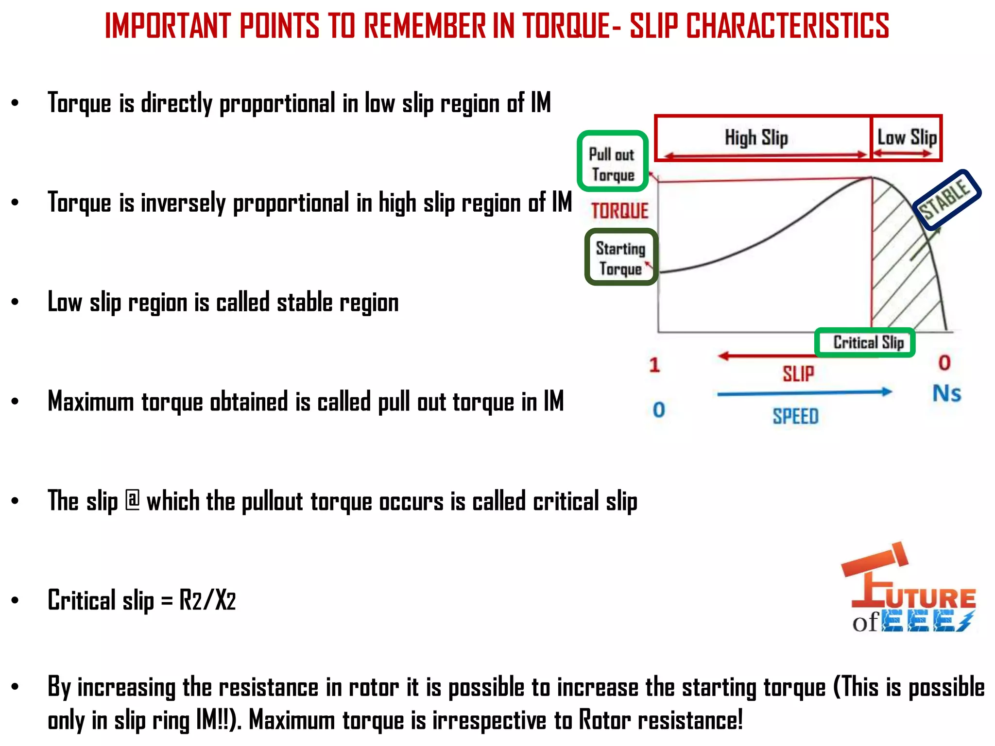
IMPORTANT POINTS TOREMEMBER IN TORQUE- SLIP CHARACTERISTICS
• Torque is directly proportional in low slip region of IM
• Torque is inversely proportional in high slip region of IM
• Low slip region is called stable region
• Maximum torque obtained is called pull out torque in IM
• The slip @ which the pullout torque occurs is called critical slip
• Critical slip = R2/X2
• By increasing the resistance in rotor it is possible to increase the starting torque (This is possible
only in slip ring IM!!). Maximum torque is irrespective to Rotor resistance!
9.
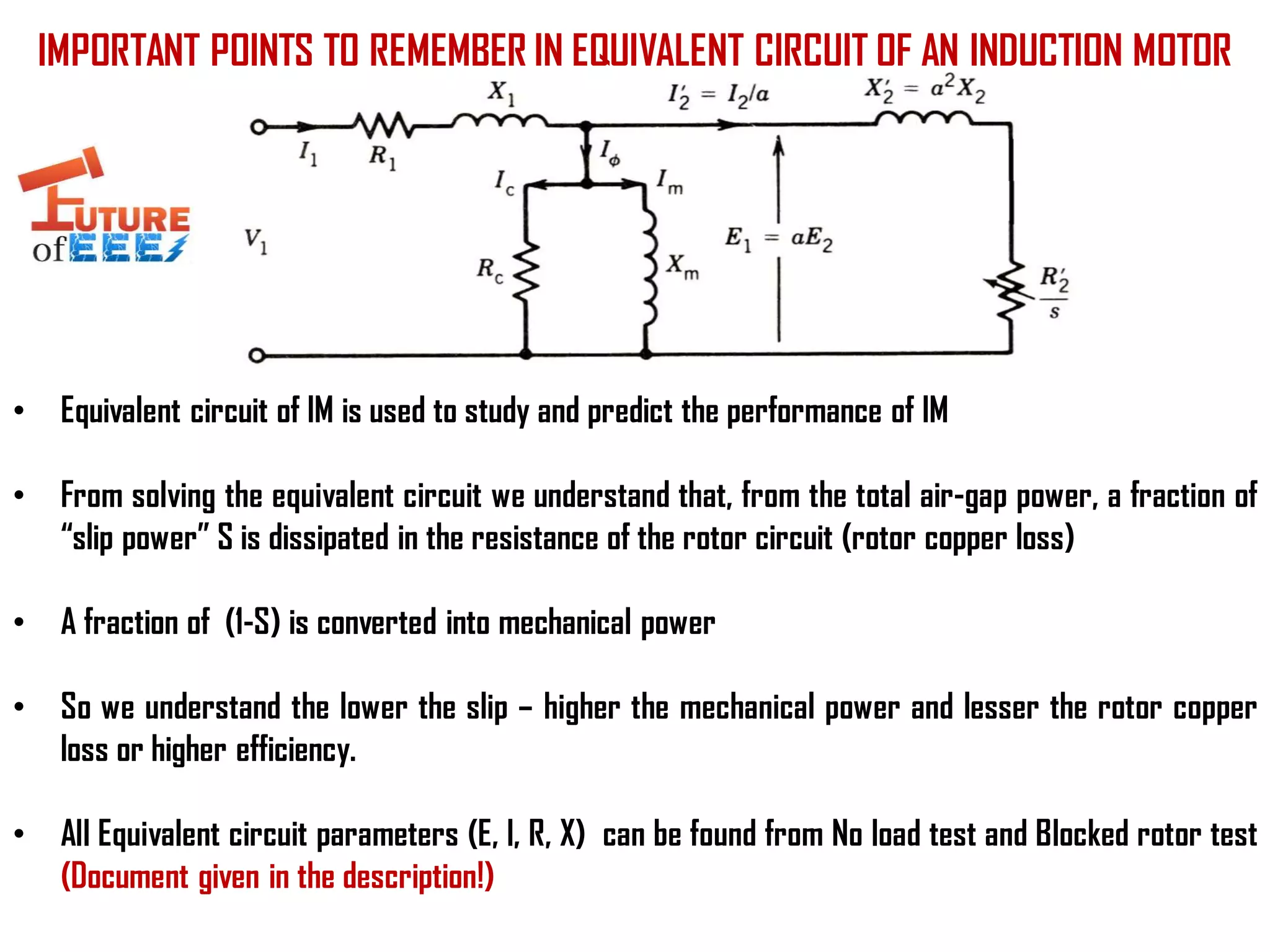
IMPORTANT POINTS TOREMEMBER IN EQUIVALENT CIRCUIT OF AN INDUCTION MOTOR
• Equivalent circuit of IM is used to study and predict the performance of IM
• From solving the equivalent circuit we understand that, from the total air-gap power, a fraction of
“slip power” S is dissipated in the resistance of the rotor circuit (rotor copper loss)
• A fraction of (1-S) is converted into mechanical power
• So we understand the lower the slip – higher the mechanical power and lesser the rotor copper
loss or higher efficiency.
• All Equivalent circuit parameters (E, I, R, X) can be found from No load test and Blocked rotor test
(Document given in the description!)