Download as PDF, PPTX
![4. Concept of the Model
6
Lead-Acid battery
Simplified Simulink Model
[Spec: C, NS]
Adjustable SOC : 0-100(%)
+
-
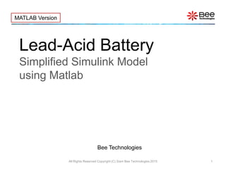
• The model is characterized by parameters: C, which represent the battery
capacity and SOC, which represent the battery initial capacity level.
• Open-circuit voltage (VOC) vs. SOC is included in the model as a behavioral
model.
• NS (Number of Cells in series) is used when the Lead-Acid cells are in series
to increase battery voltage level.
Output
Characteristics
All Rights Reserved Copyright (C) Bee Technologies Corporation 2015All Rights Reserved Copyright (C) Siam Bee Technologies 2015](https://image.slidesharecdn.com/lead-acidbatterysimplified-150422052737-conversion-gate01/85/Lead-Acid-Battery-Simplified-Simulink-Model-using-MATLAB-6-320.jpg)
![5. Pin Configurations
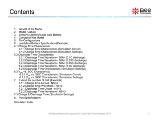
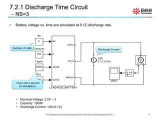
• From the Lead-Acid Battery specification, the model is characterized by setting parameters
C, NS, SOC and TSCALE.
7
Model Parameters:
All Rights Reserved Copyright (C) Bee Technologies Corporation 2015
Probe
“SOC”
C is the amp-hour battery capacity [Ah]
– e.g. C = 1, 50, or 100 [Ah]
NS is the number of cells in series
– e.g. NS=1 for 1 cell battery, NS=2 for 2 cells
battery (battery voltage is double from 1 cell)
SOC is the initial state of charge in percent
– e.g. SOC=0 for a empty battery (0%),
SOC=100 for a full charged battery (100%)
TSCALE turns TSCALE seconds(in the real world)
into a second(in simulation)
– e.g. TSCALE=60 turns 60s or 1min (in the real
world) into a second(in simulation),
TSCALE=3600 turns 3600s or 1h into a
second.
All Rights Reserved Copyright (C) Siam Bee Technologies 2015](https://image.slidesharecdn.com/lead-acidbatterysimplified-150422052737-conversion-gate01/85/Lead-Acid-Battery-Simplified-Simulink-Model-using-MATLAB-7-320.jpg)
![6. Lead-Acid Battery Specification
(Example)
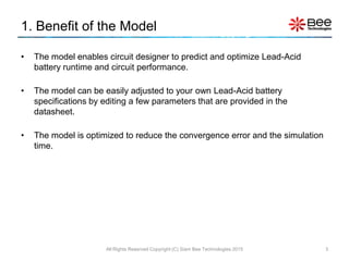
• The battery information refer to a battery part number MSE Series of GS YUASA.
8
Battery capacity is input
as a model parameter
All Rights Reserved Copyright (C) Bee Technologies Corporation 2015
Table 1
Nominal Voltage 2.0 [Vdc] /Cell
Capacity 50Ah
Rated Charge 0.1C10A
Voltage Set 2.23 [Vdc] /Cell
Charging Time 24 [hours] @ 0.1C10A
All Rights Reserved Copyright (C) Siam Bee Technologies 2015](https://image.slidesharecdn.com/lead-acidbatterysimplified-150422052737-conversion-gate01/85/Lead-Acid-Battery-Simplified-Simulink-Model-using-MATLAB-8-320.jpg)
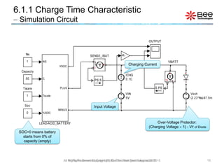
![6.1 Charge Time Characteristic
9
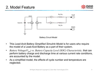
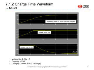
• Voltage Set: 2.23V /Cell
• Charging Current: 5.0A (0.1C Charge)
• Charging Time: 24 [hours] @ 0.1C10A
Current: 5A (0.1C10A)
Voltage Set=2.23V
Datasheet Simulation
All Rights Reserved Copyright (C) Bee Technologies Corporation 2015
%SOC
(Second)
All Rights Reserved Copyright (C) Siam Bee Technologies 2015](https://image.slidesharecdn.com/lead-acidbatterysimplified-150422052737-conversion-gate01/85/Lead-Acid-Battery-Simplified-Simulink-Model-using-MATLAB-9-320.jpg)
![13
0.1C discharge (5A)
All Rights Reserved Copyright (C) Bee Technologies Corporation 2015
6.2.1 Discharge Time Waveform
50Ah (0.1C discharge)
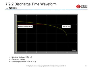
• Nominal Voltage: 2.0 [Vdc] /Cell
• Capacity: 50Ah
• 0.1C discharge (5.0A)
(Second)
All Rights Reserved Copyright (C) Siam Bee Technologies 2015](https://image.slidesharecdn.com/lead-acidbatterysimplified-150422052737-conversion-gate01/85/Lead-Acid-Battery-Simplified-Simulink-Model-using-MATLAB-13-320.jpg)
![14
0.23C discharge (11.5A)
All Rights Reserved Copyright (C) Bee Technologies Corporation 2015
6.2.2 Discharge Time Waveform
50Ah (0.23C discharge)
• Nominal Voltage: 2.0 [Vdc] /Cell
• Capacity: 50Ah
• 0.23C discharge (11.5A)
(Second)
All Rights Reserved Copyright (C) Siam Bee Technologies 2015](https://image.slidesharecdn.com/lead-acidbatterysimplified-150422052737-conversion-gate01/85/Lead-Acid-Battery-Simplified-Simulink-Model-using-MATLAB-14-320.jpg)
![15
0.65C discharge (32.5A)
All Rights Reserved Copyright (C) Bee Technologies Corporation 2015
6.2.3 Discharge Time Waveform
50Ah (0.65C discharge)
• Nominal Voltage: 2.0 [Vdc] /Cell
• Capacity: 50Ah
• 0.65C discharge (32.5A)
(Second)
All Rights Reserved Copyright (C) Siam Bee Technologies 2015](https://image.slidesharecdn.com/lead-acidbatterysimplified-150422052737-conversion-gate01/85/Lead-Acid-Battery-Simplified-Simulink-Model-using-MATLAB-15-320.jpg)
![16
1.0C discharge (50A)
All Rights Reserved Copyright (C) Bee Technologies Corporation 2015
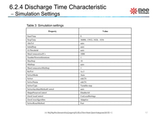
6.2.4 Discharge Time Waveform
50Ah (1.0C discharge)
• Nominal Voltage: 2.0 [Vdc] /Cell
• Capacity: 50Ah
• 1.0C discharge (50A)
(Second)
All Rights Reserved Copyright (C) Siam Bee Technologies 2015](https://image.slidesharecdn.com/lead-acidbatterysimplified-150422052737-conversion-gate01/85/Lead-Acid-Battery-Simplified-Simulink-Model-using-MATLAB-16-320.jpg)
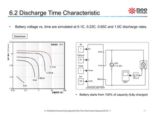
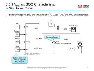
![6.3 Vbat vs. SOC Characteristic
18All Rights Reserved Copyright (C) Bee Technologies Corporation 2015
0.0
0.2
0.4
0.6
0.8
1.0
1.2
0 1 2 3
(%ofRatedCapacity)
Discharge Rate (Multiples of C)
Mesurement
Simulation
Datasheet Simulation
@25C
@25C
• Nominal Voltage: 2.0 [Vdc] /Cell
• Capacity: 50Ah
• 0.1C, 0.25C, 0.6C, 1.0 and 3.0C (discharge rates)
All Rights Reserved Copyright (C) Siam Bee Technologies 2015](https://image.slidesharecdn.com/lead-acidbatterysimplified-150422052737-conversion-gate01/85/Lead-Acid-Battery-Simplified-Simulink-Model-using-MATLAB-18-320.jpg)
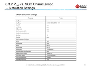
![• The battery information refer to a battery part number MSE-100-6 of GS YUASA.
21All Rights Reserved Copyright (C) Bee Technologies Corporation 2015
7. Extend the number of Cell (Example)
Voltage - Rated 6.0 [Vdc] /Cell
Capacity 100Ah
Rated Charge 0.1C10A
Voltage Set 2.23V*3 [Vdc] /Cell
Charging Time 24 [hours] @ 0.1C10A
Basic Specification
Lead-Acid needs 3 cells
to reach this voltage level
The number of cells
in series is input as
a model parameter
0.2
6
Acid-Lead
VoltageNominal
RatedVoltage
NS
All Rights Reserved Copyright (C) Siam Bee Technologies 2015](https://image.slidesharecdn.com/lead-acidbatterysimplified-150422052737-conversion-gate01/85/Lead-Acid-Battery-Simplified-Simulink-Model-using-MATLAB-21-320.jpg)
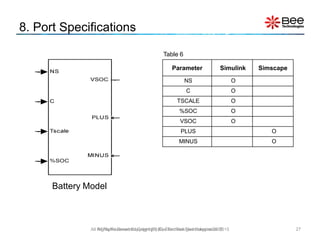

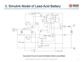
This document describes a simplified Simulink model of a lead-acid battery that can be used to simulate charge and discharge characteristics. The model accounts for battery voltage (Vbat) versus state of charge (SOC) and can simulate charge/discharge times at various current rates. It includes example simulations for a 50Ah battery showing charge time, discharge time waves at different discharge rates, and Vbat vs SOC curves. Instructions are provided on adjusting the model for different battery specifications by editing parameters like capacity and number of cells.


