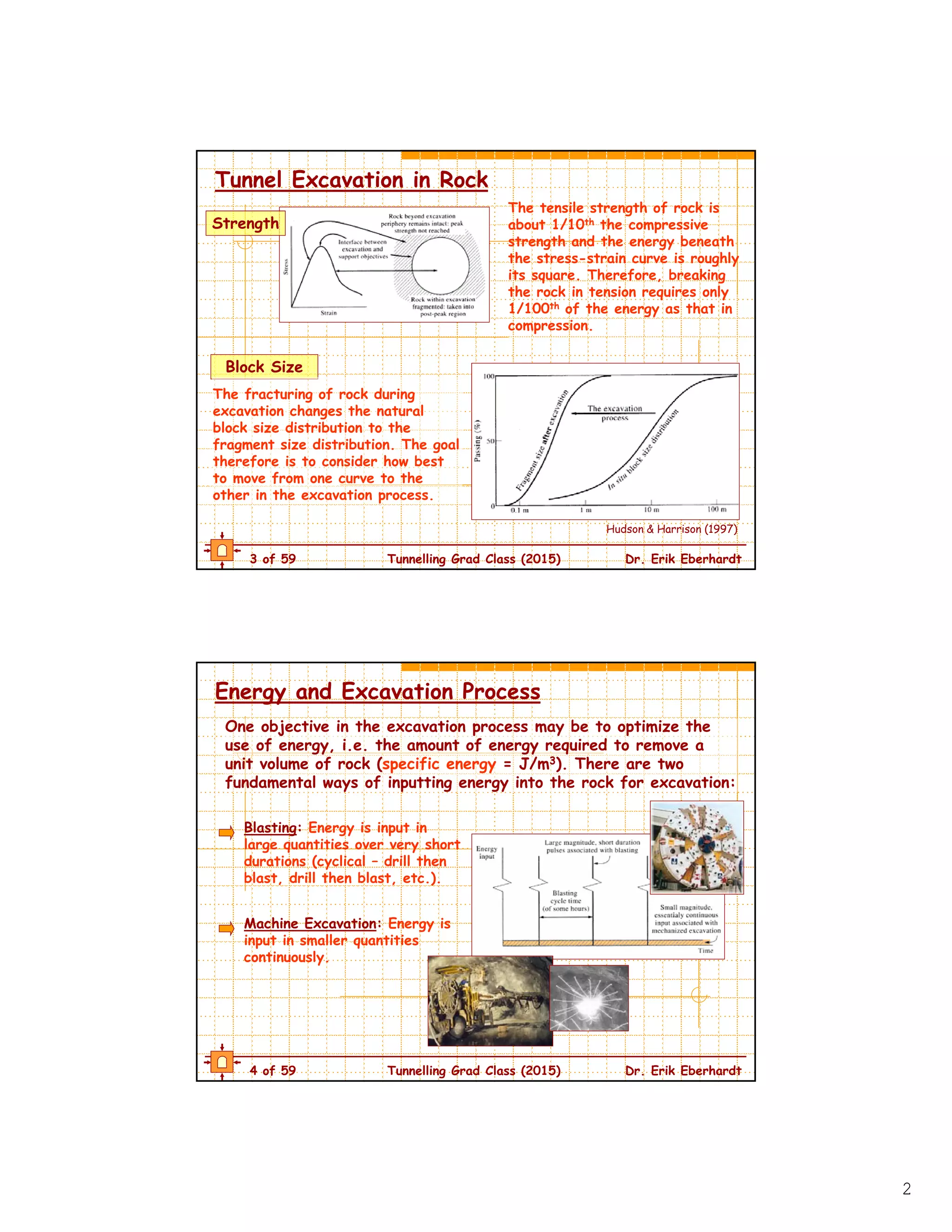
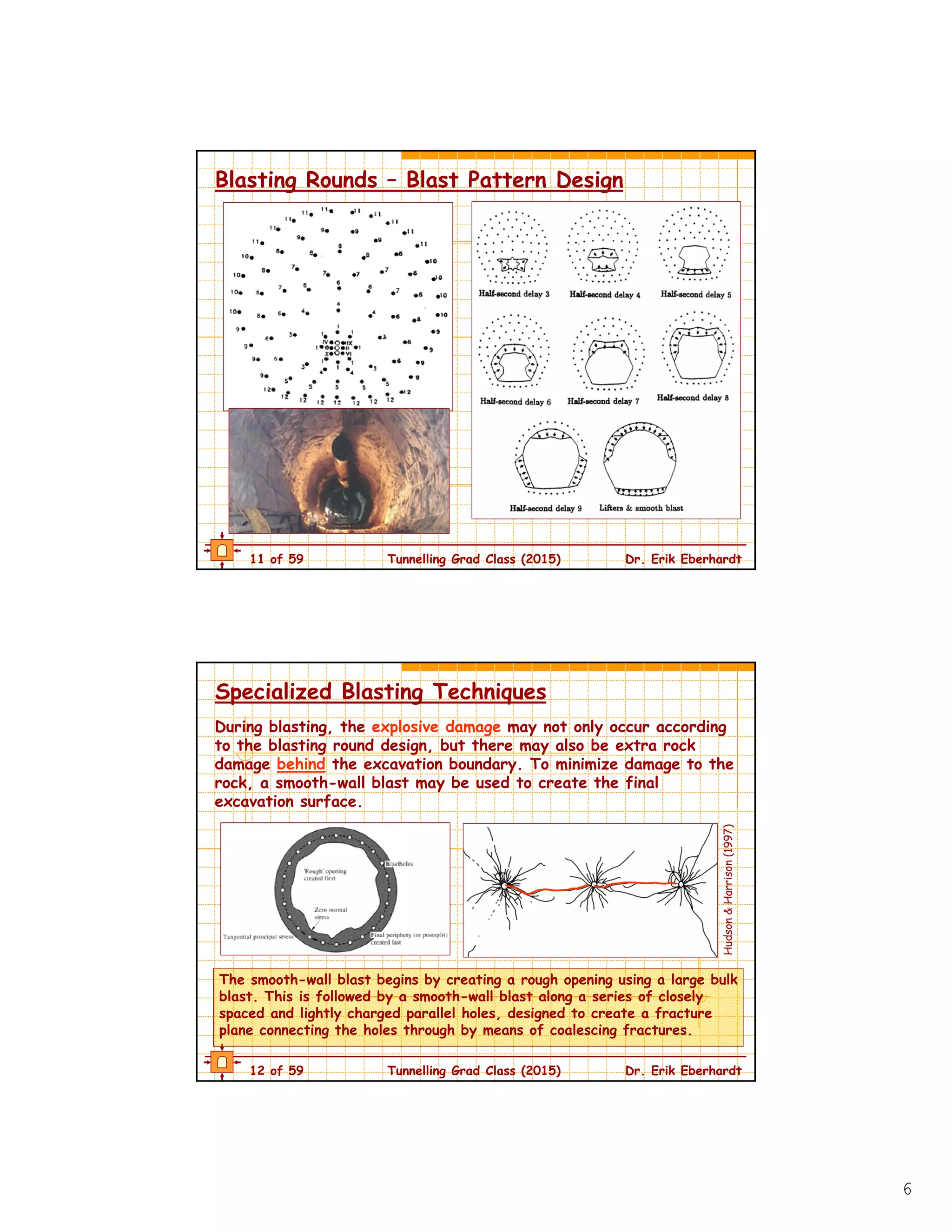
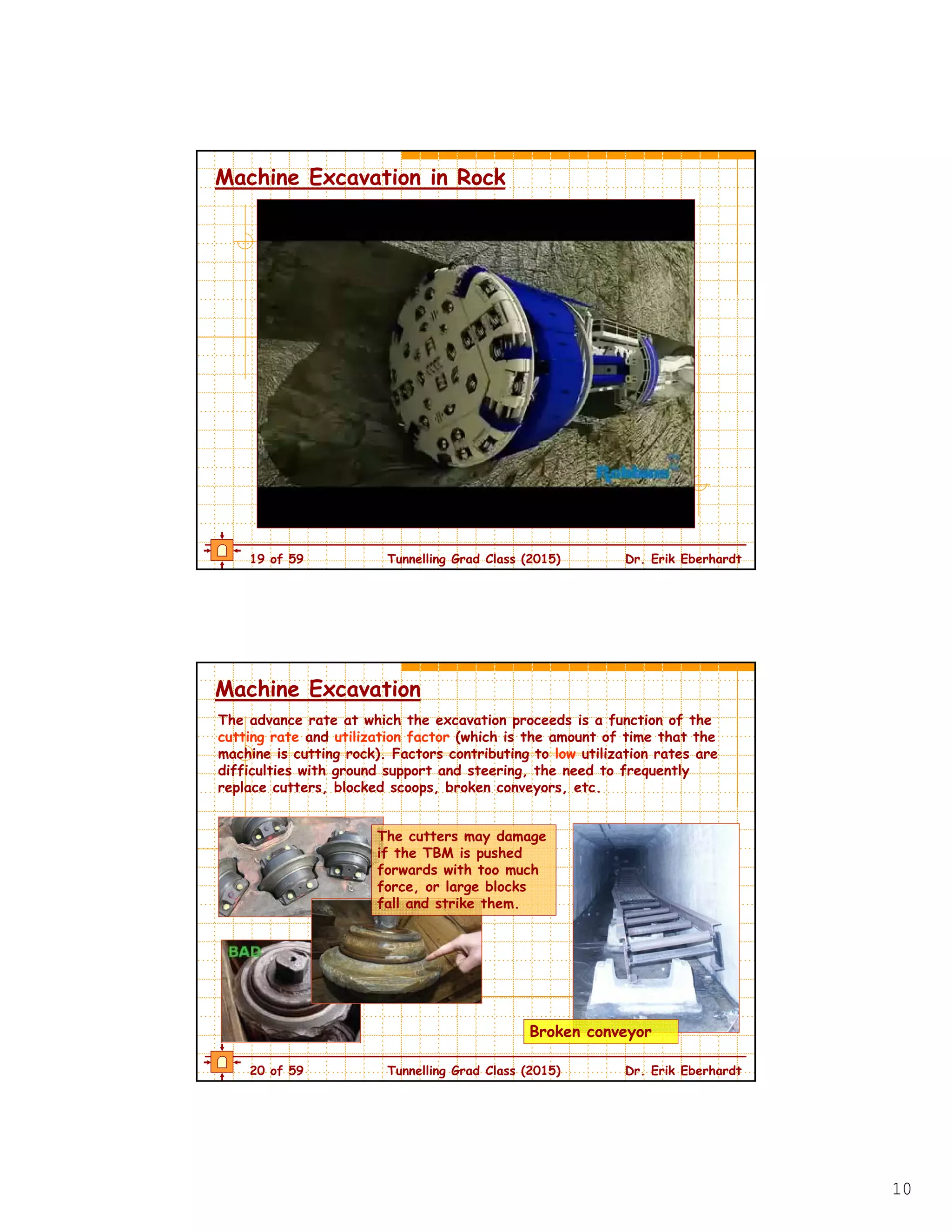
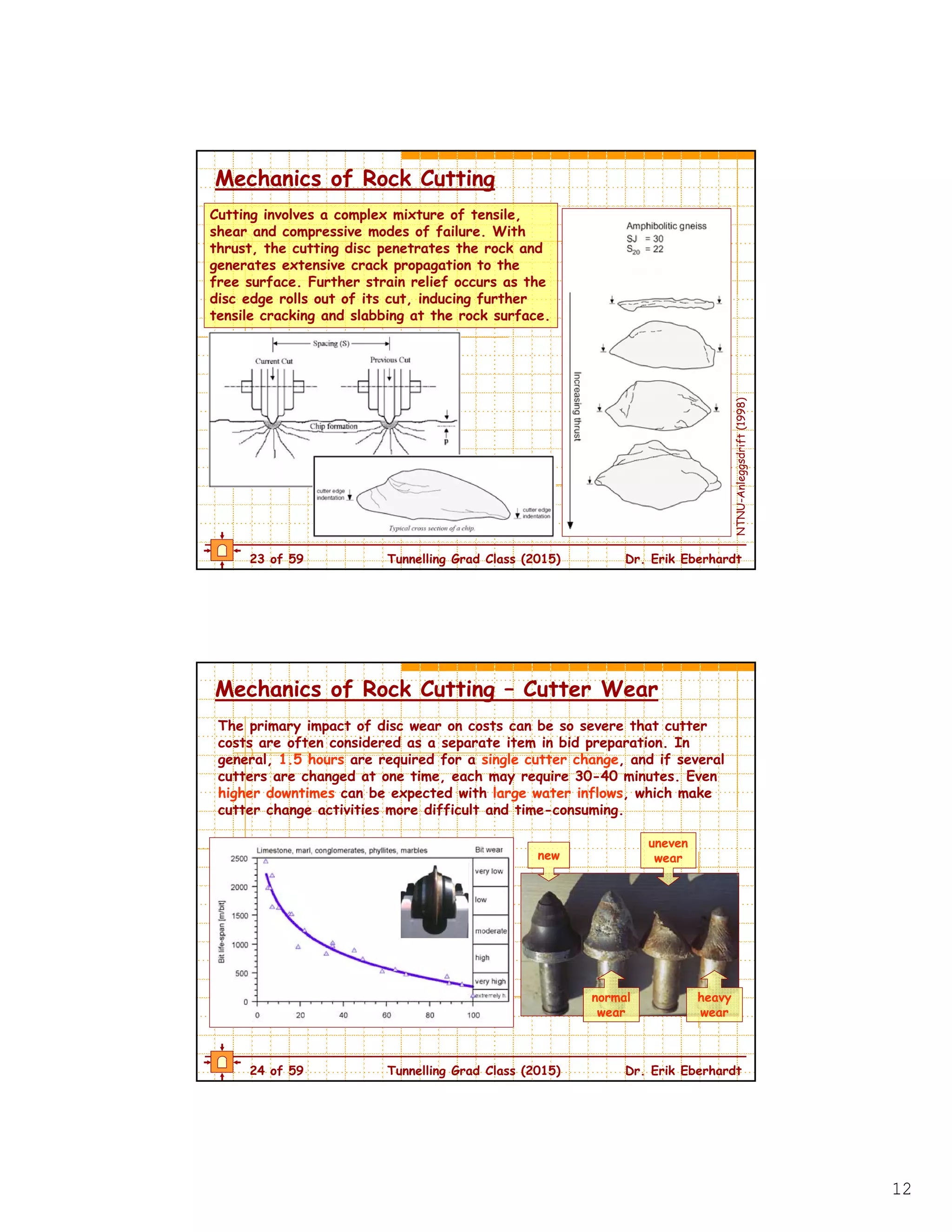
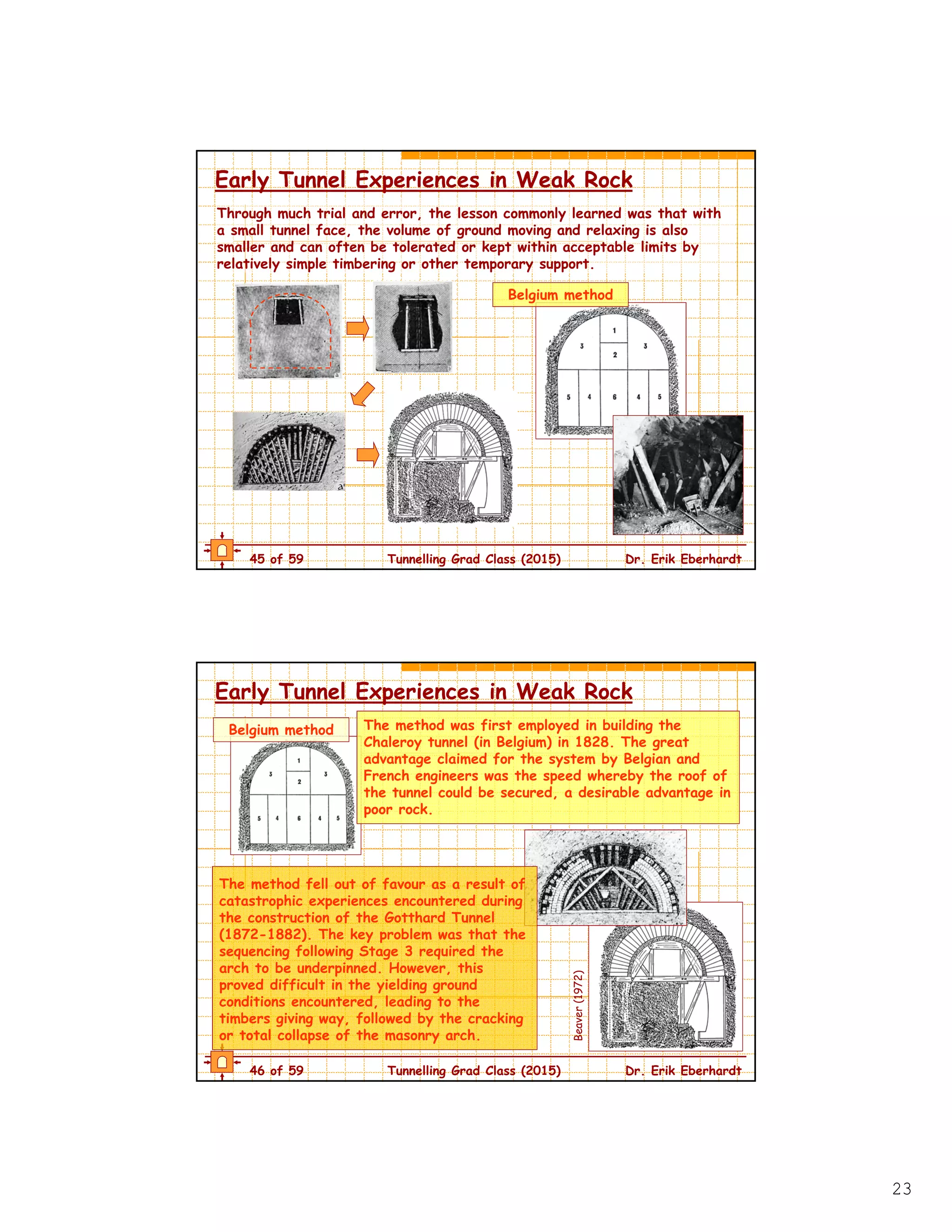
The document discusses different methods for excavating tunnels in rock, including drill-and-blast and mechanical excavation using tunnel boring machines (TBMs). Drill-and-blast involves drilling holes, loading them with explosives, and detonating them in a sequence according to a blast design. TBMs can excavate continuously using a rotating cutter head equipped with cutting tools. Factors that influence the performance of each method include rock properties, drilling/cutting rates, tool wear, and downtime. The goal is to optimize the energy used and fragmentation produced during excavation.
Tunnel making methods and tunnel boring machine mohammadsalikali
The document discusses various tunnel construction methods. It begins with an introduction to tunnels and their purposes. It then covers traditional/classical methods that were used until the late 19th century such as the English, German, and Austrian systems which involved hand excavation and timber supports. More modern methods discussed include cut-and-cover, drill-and-blast, tunnel boring machines (TBMs), immersed tunnels, and tunnel jacking. Factors in choosing a method include geological conditions, tunnel size/length, surface impacts, and construction speed/costs.
The document provides information on the New Austrian Tunneling Method (NATM). It discusses the history and origins of NATM, highlighting its first use in Austria in the 1960s. The document also outlines the key principles and features of NATM, including mobilizing the strength of the rock mass, shotcrete protection, measurements, primary lining, closing the invert, rock mass classification, and dynamic design. The sequence of executing a tunnel using the NATM approach is also described.
1. The document discusses various terminology used for underground structures related to excavation such as adits, tunnels, shafts, chambers, and portals.
2. It also discusses tunnel construction methods like shield tunneling and cut-and-cover tunneling as well as tunnel boring machines (TBMs).
3. Key challenges with underground excavations discussed include rock falls, rock bursts, squeezing ground, and ensuring long-term stability, especially in challenging ground conditions.
Lining is an integral part of Tunneling. Once the Shotcrete line ,i.e the B-line,is laid, the Kerb/Kicker or Say Beam is executed. Next Comes the Geotextile/Waterproofing Membrane. After that, C-line is laid which is referred to as inner lining.
This document summarizes various methods and procedures for tunnel construction. It discusses requirements for tunnels such as efficient transportation compared to bridges and protection in wartime. Main procedures include probe drilling, grouting, excavation using drilling and blasting, supporting structures, transporting debris, lining installation, draining, and ventilation. Methods include classical techniques using timber supports, cut-and-cover construction, drilling and blasting, tunnel boring machines (TBMs), immersed tunnels, and tunnel jacking. Choice of method depends on geological and length factors, required construction speed, and managing ground variability risks.
The document provides an overview of tunnel boring machines (TBMs) and their use for mechanized tunnel construction. It discusses various TBM types including gripper TBMs used for hard rock, slurry shields that use pressurized bentonite for ground support, and earth pressure balance machines that regulate soil pressure to support the tunnel face. The advantages and limitations of each type are presented for different ground conditions. Images and diagrams are included to illustrate the components and functions of the various TBMs.
This document discusses factors that influence the selection of bench height in open pit mining. The key considerations for bench height include planned production requirements, existing equipment size, safety regulations, and future equipment upgrades. Proper bench design is important for controlling blast depths, pit wall slopes, and wall stability. The optimal bench height balances higher stripping costs of flatter slopes with increased stability, while steeper slopes risk failures and cleanup costs outweighing production benefits. Common failure modes in pit walls include planar, wedge, circular, and toppling failures.
tunnel lining may be permanent or temporary based upon their use and requirement. design of lining is done in two parts one is temporary or initial lining design and other is permanent design of the lining. empirical and theoretical methods are major design methods.
The New Austrian Tunneling Method (NATM) involves:
1) Creating initial support on tunnel openings to prevent deterioration.
2) Excavating in short sections and applying shotcrete and metal supports.
3) Monitoring deformation with various instruments to ensure tunnel stability.
Variety of mine plans and sections & second scheduleSafdar Ali
The document lists 20 types of mine plans and sections that are required by mining regulations. They include surface plans, underground plans, vertical sections, ventilation plans, combined seam plans, geological plans, rescue plans, water danger plans, abandoned mine plans, stone dusting plans, sampling plans, firefighting plans, joint survey plans, electrical plans, subsidence plans, systematic support plans, manpower distribution plans, accident plans, and any other plans required by inspectors. The plans must show details of the mine workings, geology, infrastructure, ventilation, hazards, personnel, and accidents.
This document provides information on various topics related to tunnelling including introduction, role of geology, factors improving tunnelling, problems associated with tunnelling, future considerations, terms related to mining practices and tunnelling, tunnel service classification, methods of tunnelling, development of drills, equipment used, drilling processes, and specific drilling equipment. It discusses the importance of tunnels, describes different types of tunnels based on use and ground conditions, and outlines key factors to consider for tunnel design and construction methods.
This document discusses ground investigation for tunnelling projects. It covers objectives of ground investigation planning including suitability assessment, design, construction planning and environmental impact determination. Key risks like water ingress, ground collapse and obstructions are highlighted. Common ground conditions like dykes, wedges and timber piles are shown. Strategies and techniques for ground investigation planning, during design and construction stages are outlined. Methods for different ground types like soft ground, hard rock and karst deposits are also described. The document emphasizes comprehensive planning and supervision of ground investigation works for tunnelling projects.
NATM (New Austrian Tunneling Method ) in TunnelingHamed Zarei
1. NATM (New Austrian Tunneling Method) is a flexible tunneling method that utilizes shotcrete, wire mesh, rock bolts, and lattice girders for tunnel support. It mobilizes the strength of the rock mass and uses dynamic design that adapts the support based on rock conditions.
2. Excavation in NATM progresses from top heading to benches in poor rock. It is done in small sequential cells to support unstable ground. Primary lining of shotcrete is applied immediately after excavation.
3. Rock mass is classified using methods like RQD, RMR, and Q-factor to determine appropriate support. Flexible shotcrete and bolting allow adaptation to changing geology encountered during tunnel
This document provides information about different types of rock drilling methods. It begins with definitions of rock drilling and the main components of drilling machines. It then describes the three main types of rock drilling: 1) Percussion drilling which includes jackhammers and drifters, 2) Abrasion drilling such as blast hole drills and diamond drills, and 3) Fusion piercing drilling which uses rotating reamers and high-temperature flames. For each type, several examples are given and brief descriptions of how they operate are provided.
This document discusses rippers, which are attachments used to tear apart hard or frozen ground more efficiently. It defines rippers and includes a line diagram. Rippers excavate land faster and provide better quality output. They are used to excavate foundations, remove clay and gravel, cut drainage pipes, roads in hills, and ditches. Factors like the job size, type of ground, haul road conditions, and traction requirements determine the appropriate ripper size. Rippers require ongoing maintenance and repair, with costs increasing over the equipment's service life. Rippers are commonly used in construction to move large amounts of soil and debris and are equipped with claw-like rippers to loosen compacted materials. Ripper costs vary depending
This document provides terminology and descriptions related to underground structures like tunnels. It includes definitions of different tunnel construction elements and methods. Some key points covered include:
- Definitions of tunnel construction terms like adit, shaft, chamber, support, failure modes, and tunnelling methods.
- Descriptions of different tunnelling methods including shield tunnelling, cut-and-cover tunnelling, and tunnelling boring machines (TBMs).
- Factors that influence rock excavation for tunnels like geological structures, rock properties, and resistance to excavation.
- Examples of large irrigation tunnels including details of the Urfa Irrigation Tunnel in Turkey.
Tunnels are underground passages constructed for various purposes such as transportation, infrastructure, and military use. Key points from the document:
- Tunnels can carry vehicles, trains, water, sewage, and more underground or under water obstacles.
- They are built when roads encounter obstacles like mountains or water barriers to provide an alternative to bypassing or bridging over the obstacle.
- Tunnel construction has a long history dating back thousands of years, with modern techniques now using tunnel boring machines and advanced engineering methods.
This document discusses techniques for controlled blasting to improve environmental and safety standards. It describes methods like line drilling, trim blasting, pre-splitting, and muffle blasting that are used to control adverse impacts from blasting such as overbreak, ground vibrations, noise, and rock fractures. These techniques involve parameters like drill hole spacing, charge weight, and accurate delay timing to help fragment rock while minimizing damage to surrounding areas.
Hydraulic mining uses high-pressure water jets to break up soft rock and minerals and transport them away as slurries. It is particularly useful for extracting precious stones where explosives could damage them. The cutting rate depends on water pressure, flow rate, and nozzle design. After breaking the rock, the slurry is piped long distances in some cases. Hydraulic mining is productive, economical, and safer than conventional mining methods. It has potential applications for extracting many types of soft rocks and minerals.
This document discusses various aspects of tunnel construction including definitions, purposes, factors affecting construction, major tunnels in India, shapes of tunnels, geological surveys, design considerations, construction methods, and conclusions. It defines a tunnel as an underground passageway dug through surrounding soil or rock and enclosed except at entrances and exits. Common construction methods described are cut-and-cover, tunnel boring machine (TBM), shield technique, pipe jacking, and sprayed concrete. Design considerations include alignment, tunnel lining, groundwater control, ventilation, and investigation.
The document provides information about dragline excavators used in opencast mining. It discusses how draglines work by excavating material and dumping it without conveyors or trucks. Key points include that draglines are flexible and cost-effective for removing waste material. They work by dragging a bucket along the ground, lifting it, swinging it, and then dumping the material. The document also provides details about different dragline operation methods and specifications for draglines used at particular mining sites.
Tunnel boring machines (TBMs) are used to excavate tunnels with a circular cross-section through various ground conditions ranging from soft ground to hard rock. TBMs can bore tunnels continuously with minimal ground disturbance compared to traditional drilling and blasting methods. Modern TBMs function as a single, self-contained unit that can drill, excavate soil and rock, apply concrete segmental lining, and remove spoils, making them highly efficient for tunneling projects.
This document discusses continuous miners, an underground coal mining technology. Some key points:
1) Continuous miners use a mass production method and can be used for room and pillar and shortwall mining. Their use has increased production at some CIL mines in India to over 0.5 Mte annually.
2) Ideal conditions for continuous miners include seam thickness of 1.8-5m, gradients less than 1 in 8, and hard, dry floor conditions. Several CIL mines have been identified to introduce the technology.
3) The technology involves a continuous miner cutting coal which is loaded onto shuttle cars and transported to a feeder breaker. Roof bolting then occurs before the min
This document provides information about tunnel construction using the New Austrian Tunneling Method (NATM). It discusses the various steps of NATM tunneling including drilling, blasting, mucking, shotcreting, installing lattice girders and rock bolts, and ventilation. NATM is advantageous for tunneling in soft ground as it monitors rock deformation and designs support structures accordingly. The document outlines the typical sequence of NATM tunnel construction and importance of factors like geology and ventilation.
The document discusses various aspects of tunnel engineering. It begins by introducing tunnels and their uses for transportation. It then discusses the Thames Tunnel in London as an example. The document outlines several advantages of tunneling over other methods. It also discusses considerations for selecting tunnel routes and economies of tunneling. The remainder of the document describes various tunneling methods through both rock and soft ground, as well as tunnel drainage, lighting, ventilation, lining, and maintenance.
theories of interaction of rock cutting tools in contact with the rock, different parameters, specific energy, applications, drag, point attack picks, disc cutters, and their interaction
1) Tunnel boring machines (TBMs) are used to excavate tunnels with a circular cross-section through various ground types and diameters ranging from 1-20 meters.
2) A TBM consists of one or two large metal cylinder shields at the front, fitted with a cutting wheel, and hydraulic jacks that push the machine forward as it removes material.
3) TBMs allow for safer, more consistent tunneling compared to conventional methods and reduce risks from manual labor or explosives, though they require more supporting infrastructure and have higher costs.
Tunnelling methods can be chosen based on geological conditions, tunnel size and length, experience, and cost considerations. Classical methods from the 19th century included the English, Austrian, German, Belgian, and Italian systems which used hand excavation and timber supports. Modern methods include mechanical drilling/cutting, tunnel boring machines (TBMs), the New Austrian Tunnelling Method (NATM), immersed tunnels, and specialized methods. The tunnelling process typically involves probe drilling, grouting, excavation, supporting, muck removal, lining, drainage, and ventilation. Cut-and-cover can maintain surface traffic with reduced street widths or temporary bypasses, and uses concrete curtain walls for trench stability in urban areas.
This document summarizes segmental bridge construction techniques. Segmental bridges are constructed using precast concrete segments rather than a single continuous pour. This allows construction over bodies of water without needing intermediate supports. Two common techniques are discussed - cantilever construction where segments are cast out from each pier, and incremental launching where precast segments are erected on a launching girder. A case study of the Ganga bridge in India is provided, which used both precast and cast-in-place segments to span over 1,000 meters. Segmental construction enables longer bridge spans while reducing impacts to river traffic during construction.
This document provides an overview of the top-down construction method. It explains that in top-down construction, basement concrete slabs are poured first and act as lateral bracing for perimeter walls as subsequent levels are excavated from the bottom up. Main advantages include savings in construction time. Diagrams show the excavation process with floors poured and braced as excavation progresses downwards. Careful planning is required to properly implement this new method in Ho Chi Minh City, especially for dewatering and handling different soil types at varying depths.
This document discusses various methods of tunneling in soft soil, including timbering methods like the fore-poling method and needle beam method, as well as other methods like the shield method and compressed air method. It provides details on the sequence of operations and characteristics of different tunneling methods based on the type of soft soil present, including challenges around maintaining air pressure for compressed air tunneling.
Shield Tail Deformations - Experiences, Mechanics and Lessonscoen_van_der_vliet
The document summarizes research into deformations experienced by the tail sections of two slurry shields used to construct a 6km road tunnel under a waterway. Measurements found deformations of up to 20mm in the shield tails after installation. Analysis determined the primary load carrying system of circumferential membrane forces was too weak, buckling under pressures around 10-16 bar. Recommendations included improving design models to account for gaps without soil support, using higher load factors for deformations, incorporating weaker details, and monitoring shield tails during construction to detect issues and enable recovery.
The document discusses guidelines for tendering and costing NATM (New Austrian Tunnelling Method) contracts according to Austrian Standard ÖNORM B 2203-1. Key points include:
1) Time-dependent costs are divided into phases and tendered separately from quantity-dependent items to account for uncertainties. Advance rates are set for predicted tunnelling classes.
2) Tunnelling classes are defined in tender documents to estimate support requirements and advance rates. Costing is based on a cycle analysis for each class.
3) Documents provide for payment for over-excavation, excess concrete, water management and other contingencies according to measured quantities rather than design.
The document discusses a bridge (Bridge No. 91) over the Yadkin River that was experiencing settlement at Bent No. 7. An investigation was conducted which included reviewing plans, performing subsurface exploration, and interviewing divers. The investigation found that the footing at Bent No. 7 was not bearing on bedrock as planned, but rather on alluvial deposits, leading to the settlement over time.
This document discusses tunneling and provides information on various topics related to tunnels. It introduces tunnels and their uses for transportation. It covers topics like lighting, ventilation, lining, size and shape of tunnels. It describes different types of tunnels and their applications. It also discusses advantages of tunnels and some limitations. In conclusion, it states that tunneling is effective for high traffic densities and has environmental benefits, but requires specialized expertise.
Closing Lecture: World Tunnel Congress 2014, Iguassu Falls, Brazil
Quo Vadis Tunnel Engineering?Predicting the Unpredictable
by Z T Richard Bieniawski v. Preinl
This document discusses directional drilling techniques and their applications. It begins by defining directional drilling as deflecting a wellbore in a specified direction to reach a target below the surface. It then lists several applications of directional drilling including drilling multiple wells from a single location, drilling in inaccessible locations, avoiding geological problems, sidetracking, relief well drilling, and horizontal drilling. The document also discusses directional drilling applications in mining, construction, and geothermal engineering. It provides details on well profiles, azimuth and quadrants, horizontal well types, and directional drilling assemblies for building angle and holding angle.
A casting yard is where concrete structures like segments, parapets, and beams are cast for bridges and viaducts. It must be easily accessible from project sites and have 25-40 acres of land. Concrete elements are cast using long-line or short-line methods, cured, and then transported to worksites. Quality control includes geometry control during casting and testing of concrete slump, setting time, and compressive strength. Precast concrete has higher quality control compared to cast-in-place concrete.
Dams are solid barriers constructed across rivers to store flowing water for uses like drinking water, irrigation, hydropower, flood control and recreation. The main purposes of dams worldwide are irrigation (48.6%), hydropower (17.4%), and water supply (12.7%). A dam has a dam body, reservoir, spillway, intake structures and may include a sluiceway or diversion facilities. Dams are classified by size, height, and structural design, with the main types being gravity dams, arch dams, buttress dams, embankment dams and composite dams. While dams provide benefits like food and energy, they can also cause issues like flooding, disruption of ecosystems and communities.
This document discusses precast concrete construction. Some key points:
- Precast concrete elements are cast and cured off-site then transported for assembly, allowing more efficient production and quality control.
- Elements include slabs, beams, columns, and wall panels that are joined on-site through embedded bolts, plates, and grouted connections.
- The precasting process involves casting concrete around prestressing strands to add strength, then cutting sections and transporting them for erection.
Precast concrete construction involves casting concrete structural elements at a manufacturing facility rather than on site. This allows for rapid construction, high quality control, and easy incorporation of prestressing. Precast concrete provides advantages like speed of erection, durability, and economy, but also has disadvantages such as weight, limited flexibility in design, and need for skilled workmanship and lifting equipment on site. Common precast concrete elements include walls, slabs, beams, and structural framing using techniques like welded plates and rebar splicing.
This document discusses the process of selecting bridge types and provides an overview of common bridge types. It describes evaluating potential bridge types based on engineering constraints, costs, environmental and stakeholder impacts. Key bridge types are then summarized, including girder, segmental concrete, truss, arch, cable-stayed, suspension and movable bridges. Their structural properties, construction methods, advantages and challenges are outlined.
Segmental bridge construction involves building bridges out of precast concrete segments. This allows for longer spans than traditional methods by reducing the need for intermediate piers. There are several techniques for segmental bridge construction including cast-in-place using form travelers, incremental launching where segments are cast and then pushed out over supports, and precast segment erection using launching girders. Segmental construction enables building bridges more quickly and over existing infrastructure with minimal traffic disruptions.
Challenges of Tunneling-- A Peep Into The Exciting World of TunnellingIEI GSC
By Shri Manoj Verman, President, Indian National Group of ISRM
President, International Commission on Hard Rock Excavation
Vice President, Indian Society of Engineering Geology
at 31st National Convention of Civil Engineering
organised by
Gujarat State Center, The Institution of Engineers (India)
at Ahmedabad
Patrick Biro, P. Eng. & Dave Groot will provide a complete overview of common tunnel liner and tunnel rehabilitation solutions in Canada. The presentation will include various trenchless solutions for tunneling and relining, including structural plate, corrugated steel & plastic pipe, steel-reinforced polyethylene pipe and spiral wound liners.
The document discusses the design of precast segmental tunnel linings used for shield tunneling. It covers key aspects of segmental lining design including geometry, calculation of internal forces, reinforcement design, segment manufacture, waterproofing, and types of tunnel boring machines (TBMs) used for shield tunnel excavation.
This document provides an overview of tunneling, including the purposes of tunnels, effects of tunneling on the ground, tunnel lining, economic aspects, geological considerations, overbreak, and examples of important tunnels. Tunnels are used for transportation, utilities, and protection from hazards. They affect the surrounding ground and require lining for structural integrity and waterproofing. Cost, time, and construction method are economic factors to consider. Geological conditions like rock type influence tunnel design and construction challenges like overbreak. The Pir Panjal Railway Tunnel in India is highlighted as a significant tunnel project.
Tunnel T80 across Pir Panjal Mountain Range: The Longest Transportation Tunne...Hitesh Khanna
The Presentation Covers the General Technical Features of Tunnel T 80 across Pir Panjal Mountain Range, for Kashmir Rail Link. This presentation was made at Civil Engineering Society, IIT Kanpur on 30th September 2013.
This document discusses various tunnelling methods for soft ground, including cut and cover, shield tunnelling using compressed air or slurry, and earth pressure balance tunnelling. Cut and cover involves excavating a trench and placing pre-cast concrete segments, and was used for 75% of the Canada Line project in Vancouver. Shield tunnelling methods provide constant support to the advancing tunnel face. Compressed air shields fell out of favor due to health and safety issues, while slurry shields use bentonite slurry to support the face but require expensive separation plants. Earth pressure balance tunnelling was developed to address limitations of slurry shields, supporting the face through pressure control without slurry or separation plants.
The document discusses brittle fracture and stress-controlled failure in tunneling. It describes how stresses concentrate and relax around underground excavations, which can lead to problems like spalling and rockbursts. Spalling occurs when stresses concentrate and exceed the rock strength, causing slabs or wedges to detach from the tunnel walls or roof. Rockbursts are sudden violent failures caused by the buildup and release of strain energy. The document examines failure mechanisms from both phenomenological and mechanistic perspectives, discussing theories like Mohr-Coulomb criteria and Griffith crack propagation theory. It emphasizes that brittle rock strength is stress-dependent and damage initiates at stresses well below peak strength.
The document discusses the New Austrian Tunnelling Method (NATM) for excavating tunnels in weak rock. Some key points of the NATM include: (1) controlling ground deformations by applying early temporary support like rock bolts and shotcrete, (2) using flexible support that deforms with the ground, and (3) closing the tunnel invert quickly to form a load-bearing ring. The NATM also emphasizes monitoring ground movements and revising support as needed to maintain stability. While economical by matching support to conditions, the NATM requires cooperation between engineers to determine daily support requirements.
Drilling and blasting involves different types of drilling like rotary and percussive drilling. Rotary drilling uses tricone bits and drag bits while percussive uses hammers. Factors like burden, spacing, stemming affect blast design. Explosives like TNT, dynamite and safety fuses are used. Blasted rocks undergo processes like radial cracking and flexural rupture. Controlled blasting techniques like presplitting and cushion blasting reduce overbreak. Explosives have risks but when used properly can efficiently fracture rocks for excavation.
New burn cut blast design in drives enhances drilling blasting efficiency wit...partha sharma
A new Burn-Cut blast pattern has been designed for drives, declines and ramps in underground metal mines, to replace a design (of Decked-Burn with more number of holes), which was giving number of blast failures, such as ‘Under_Blast’ - difficult to handle. The new Burn-cut design contains less number of blast-holes and Reamer than earlier Decked-Burn-cut. Decked system has been removed to make the charging operation easier. This enables to increase explosives energy in a hole and to reduce stemming length in order to eliminate above blast failures. Moreover, requirement of Detonators is reduced, as Decked system has been abolished. Total explosives quantity has been reduced marginally. Thus, drilling efficiency and cost effectiveness has been achieved. Entire process has been done by changing the original pattern / system in three phases.
Tunnel-boring machines are the primary gear for the development of trenchless underground designing tasks, for example, rail travel, civil designing, railroad tunnels, and so on. This paper reviews various tunnel boring machine types, cutting tools, and machine performance through several case studies.
The document provides an overview of tunnel boring machines (TBMs) and their history and use in tunnel construction. Some key points:
- The first shield-based tunneling method was developed by Marc Isambard Brunel in 1825 to construct the Thames Tunnel, though miners still did the digging. Later improvements led to round-shaped "tube" tunnels in London.
- Early mechanical TBMs in the mid-1800s had limited success digging through rock and shale. The modern breakthrough was the rotating cutting head, based on earlier percussion drills.
- TBMs can be specialized for different soil/rock types, using slurry, earth pressure balance, or cutting wheels for rock.
Tunnel-boring machines are the main equipment for the construction of trenchless underground engineering projects such as rail transit, municipal engineering, railway tunnels, etc. This paper reviews various tunnel boring machine types, cutting tools, and machine performance through several case studies. It was found that these machines are highly efficient in various projects associated with hydropower, sewerage, water supply, machination, and transportation.
Wall control blasting practices at ksladag gold mineAlan Monzon
This document summarizes wall control blasting practices at the Kisladag Gold Mine in Turkey. It describes the benchmark presplit and trim blast designs used, which generally produced high quality pit walls with minimal crest loss. However, a minor slope failure occurred, prompting an evaluation. Modified designs were implemented, including 10m benches at a 70° slope and changes to presplit and trim designs. These minimized crest loss to less than 1.5m. A heat map of crest loss for the entire pit was also prepared based on lithology and rock structure to further improve wall stability.
A Review Study on Methods of Tunneling in Hard Rocksijsrd.com
This article presents a review on the different methodologies that are used for tunnels excavations in hard rocks in present era. Growing needs for modern transportation and utility networks have increased the demand for a more extensive and elaborate use of underground space or through high mountains / hills. As a result, more projects have to be completed in various ground conditions and one of which is more challenging is to carry out excavation work in hard rocks. Significant technological advances have rendered these projects possible, but have also given rise to new challenges as many of these projects have to be completed in difficult conditions, with very strict environmental constraints, particularly in urban areas where the potential impact of tunneling on existing structures is a major concern. This paper addresses the main aspects of tunneling and underground works performed in hard rocks. A summary is presented of the more recent advances and widely adopted techniques in these regards.
Drilling methods are used in construction and mining to drill holes in rock and earth. There are various types of drilling including rotary, percussion, and rotary-percussion. Rotary drilling uses rotation to cut holes while percussion drilling uses repeated impact force. Different drilling methods and equipment are suited to different applications depending on factors like the rock properties and depth of drilling required. Common drilling equipment includes jackhammers, stopers, drifters, and wagon drills which can be powered pneumatically, hydraulically, or electrically.
1. The document discusses various drilling methods used for extracting samples from underground rock formations. It describes percussion drilling, rotary drilling, and several variations of each method.
2. Percussion drilling involves lifting and dropping heavy tools to break rock and uses steel casing to prevent cave-ins. Variations described are down-the-hole (DTH), top hammer, and circulation drilling.
3. Rotary drilling uses a powered rotating cutting head to drill holes while lubricating with air, water, or mud. Variations are auger drilling, calyx drilling, and diamond drilling. Diamond drilling creates precise holes using diamond-tipped drill bits and is useful for applications like concrete sampling.
Buffer blasting presentation for Coal 2016.rev1John Latilla
Targeted buffer blasting is used at Ukhaa Khudag coal mine in Mongolia to stabilize slopes containing bedding plane shears by disrupting the shear planes. Buffer blasts increase slope stability by raising the cohesion and friction angle of the rock mass. Analysis shows buffer blasting can allow slopes up to 13 degrees above the dip of the coal seams. Of the cases studied, 86% of buffer blasts successfully stabilized slopes. Improved planning is needed to proactively identify areas needing buffer blasts.
IRJET - Enhancing Productivity in Opencast Mines – A Quantified ApproachIRJET Journal
This document discusses enhancing productivity in opencast mines through improved rock fragmentation from blasting. It begins by defining rock fragmentation and describing how the size distribution of blasted rock fragments affects operations downstream like loading, hauling, and crushing. Optimal fragmentation minimizes oversize rocks while avoiding too many fines.
The document then examines the factors that influence rock fragmentation from blasting, including properties of the rock mass and explosive as well as blast design parameters like drilling pattern, charge weight, and delay timing. It discusses how fragmentation is assessed through metrics like mean fragment size and shovel performance. Finally, it stresses that the blasted rock profile and fragment sizes must complement the loading and hauling equipment used in the mine to maximize productivity
The document summarizes shaft sinking methods for underground mining. It defines shaft sinking as the excavation of a vertical or inclined opening from the surface for transport of materials, ventilation, pumping water, and hoisting ore. Conventional shaft sinking involves drilling, blasting, mucking out debris, installing temporary supports like timber boards or steel rings, and eventually permanent concrete lining. Newer mechanical methods using vertical shaft machines or tunnel boring machines can significantly increase safety and productivity compared to conventional drilling and blasting. Selecting the appropriate sinking method depends on factors like depth, geology, costs, and available technology.
This document discusses principles of rock drilling for excavation by blasting. It describes two main drilling methods - rotary drilling and percussive drilling. Rotary drilling can be further divided into rotary cutting and rotary crushing using different drill bits. It is commonly used for large blast holes but has limitations in drilling non-vertical holes. Percussive drilling breaks rock through hammering impacts generated by pneumatic or hydraulic rock drills and transmits energy to the drill bit.
This document discusses different methods for drilling blast holes in rock for excavation purposes. It describes rotary drilling which uses rotation to cut or crush rock with drill bits. Rotary drilling is best for softer rocks and produces larger diameter holes but cannot drill at angles from vertical. Percussive drilling uses hammering impacts from pneumatic or hydraulic rock drills to break rock and can drill angled holes better than rotary drilling. The document provides an overview of key parameters for planning blast hole drilling and compares products from Atlas Copco for different applications.
The document discusses various components and equipment used in drillstrings. It describes the different types of tubulars used in drillstrings including drill pipes and drill collars. It also discusses various drillstring equipment such as stabilizers, reamers, hole-openers, and bottom hole motors that are used to provide stability and directional control. Finally, it covers other drillstring equipment like manual tongs used to make connections, top drives used as an alternative to rotary tables, and positive displacement motors that convert hydraulic energy to rotate the drill bit.
Design and Preparation of Aluminium Nozzle Using Metal Spinning ProcessNitesh Sharma
This new technique comprises of single-piece production of nozzle i.e. convergent, and divergent parts without the involvement of welding these parts separately to bolster the strength of the nozzle and increasing the efficacy of the nozzle.
The Gotthard Base Tunnel project in Switzerland faced significant geological uncertainties and challenges during construction. Known risks included water inflows and weak ground conditions in brittle fault zones, squeezing ground in weak rock masses, and potential rockbursts in deep, high-stress sections. Unknown risks that emerged included unexpectedly thick and extensive buried valleys during the construction of the Lötschberg Base Tunnel, which caused a major flood during construction. For the Gotthard Base Tunnel, running ground conditions in water-saturated dolomite formations and the crossing of subhorizontal faults near Faido presented challenges that led to project delays and cost overruns. Addressing these complex geological conditions and unknowns required extensive geological investigations and flexible tunnel construction
Similar to Tunnelling & underground design (Topic5-hard & weak rock tunnelling) (20)
This document discusses blasting rock through the use of explosives. It provides an overview of blast design and the types of explosives commonly used, including dynamite, slurries, and ANFO. It explains concepts like burden, stemming, and delay devices. The goal of the document is to provide guidance on designing blast hole layouts and calculating explosive amounts for effective blasting of rock.
numerical study and analytical solution of P-wave attenuation insensitive und...Hamed Zarei
1) The document analyzes P-wave attenuation in underground rock structures through both analytical and numerical methods.
2) Analytical and numerical results show that any vacuum or cavity in rock mass greatly increases P-wave attenuation, while rock material with mechanical strength properties in a virtual space decreases attenuation and increases wave energy transmission.
3) Key parameters analyzed include the density and properties of virtual spaces and joints, and results show that factors like cavity thickness and density contrast have significant effects on wave attenuation.
Intelligent back analysis using data from the instrument (poster)Hamed Zarei
This document presents a model using artificial neural networks for back analysis of tunnel monitoring data from the Chehel Chai water conveyance tunnel in Iran. Input data from 27 parameters across 3 categories were used to train a neural network model on results from 18 convergence stations. The trained model was then able to accurately estimate rock mass elasticity and in situ stress values based on new monitoring data, demonstrating its effectiveness for intelligent back analysis of future tunnel monitoring results.
Tunnelling & underground design (Topic3-geotechnical data baseline reports)Hamed Zarei
This document discusses risk management in tunneling projects. It begins by providing context on managing hazards in tunneling projects such as contractual disputes, unforeseen conditions, and equipment failures. It then discusses how contracts are used to manage financial risk and trends toward design-build contracts with tight schedules and budgets. An example is given of the St. Gotthard tunnel project that went over budget and late due to pressure to meet deadlines. The document outlines the risk management process of identifying hazards, analyzing probability and consequences, evaluating risk, and implementing risk reduction measures. It discusses owner-contractor roles and responsibilities in risk management as well as types of tunneling contracts and approaches to construction delivery such as design-build. The document concludes
Tunnelling & underground design (Topic1-introduction to the tunnelling industry)Hamed Zarei
This document provides an overview of past and present tunnelling projects and challenges. It discusses the stuck Bertha tunnel boring machine in Seattle which has been stuck since 2013 due to overheating. It also discusses cost overruns and litigation on the Seymour-Capilano Twin Tunnels project in BC. Finally, it provides details on the course topics, lectures, and assignments for an introduction to tunnelling class.
Modeling of twain Tunnel water conveyanceHamed Zarei
1. The document discusses creating a tunnel model using PLAXIS software, including defining the geometry, material properties, and boundary conditions of the tunnel and surrounding rock.
2. A horseshoe-shaped tunnel with a diameter of 5.3m and space of 12m between tunnels is modeled. Rock and shotcrete material properties are input along with standard earthquake boundary conditions.
3. Dynamic analysis is performed by applying a prescribed displacement at the bottom boundary and vertical harmonic load to model an earthquake, with results viewed in output graphs.
VARIABLE FREQUENCY DRIVE. VFDs are widely used in industrial applications for...PIMR BHOPAL
Variable frequency drive .A Variable Frequency Drive (VFD) is an electronic device used to control the speed and torque of an electric motor by varying the frequency and voltage of its power supply. VFDs are widely used in industrial applications for motor control, providing significant energy savings and precise motor operation.
Design and optimization of ion propulsion dronebjmsejournal
Electric propulsion technology is widely used in many kinds of vehicles in recent years, and aircrafts are no exception. Technically, UAVs are electrically propelled but tend to produce a significant amount of noise and vibrations. Ion propulsion technology for drones is a potential solution to this problem. Ion propulsion technology is proven to be feasible in the earth’s atmosphere. The study presented in this article shows the design of EHD thrusters and power supply for ion propulsion drones along with performance optimization of high-voltage power supply for endurance in earth’s atmosphere.
Advanced control scheme of doubly fed induction generator for wind turbine us...IJECEIAES
This paper describes a speed control device for generating electrical energy on an electricity network based on the doubly fed induction generator (DFIG) used for wind power conversion systems. At first, a double-fed induction generator model was constructed. A control law is formulated to govern the flow of energy between the stator of a DFIG and the energy network using three types of controllers: proportional integral (PI), sliding mode controller (SMC) and second order sliding mode controller (SOSMC). Their different results in terms of power reference tracking, reaction to unexpected speed fluctuations, sensitivity to perturbations, and resilience against machine parameter alterations are compared. MATLAB/Simulink was used to conduct the simulations for the preceding study. Multiple simulations have shown very satisfying results, and the investigations demonstrate the efficacy and power-enhancing capabilities of the suggested control system.
Use PyCharm for remote debugging of WSL on a Windo cf5c162d672e4e58b4dde5d797...shadow0702a
This document serves as a comprehensive step-by-step guide on how to effectively use PyCharm for remote debugging of the Windows Subsystem for Linux (WSL) on a local Windows machine. It meticulously outlines several critical steps in the process, starting with the crucial task of enabling permissions, followed by the installation and configuration of WSL.
The guide then proceeds to explain how to set up the SSH service within the WSL environment, an integral part of the process. Alongside this, it also provides detailed instructions on how to modify the inbound rules of the Windows firewall to facilitate the process, ensuring that there are no connectivity issues that could potentially hinder the debugging process.
The document further emphasizes on the importance of checking the connection between the Windows and WSL environments, providing instructions on how to ensure that the connection is optimal and ready for remote debugging.
It also offers an in-depth guide on how to configure the WSL interpreter and files within the PyCharm environment. This is essential for ensuring that the debugging process is set up correctly and that the program can be run effectively within the WSL terminal.
Additionally, the document provides guidance on how to set up breakpoints for debugging, a fundamental aspect of the debugging process which allows the developer to stop the execution of their code at certain points and inspect their program at those stages.
Finally, the document concludes by providing a link to a reference blog. This blog offers additional information and guidance on configuring the remote Python interpreter in PyCharm, providing the reader with a well-rounded understanding of the process.
Null Bangalore | Pentesters Approach to AWS IAMDivyanshu
#Abstract:
- Learn more about the real-world methods for auditing AWS IAM (Identity and Access Management) as a pentester. So let us proceed with a brief discussion of IAM as well as some typical misconfigurations and their potential exploits in order to reinforce the understanding of IAM security best practices.
- Gain actionable insights into AWS IAM policies and roles, using hands on approach.
#Prerequisites:
- Basic understanding of AWS services and architecture
- Familiarity with cloud security concepts
- Experience using the AWS Management Console or AWS CLI.
- For hands on lab create account on [killercoda.com](https://killercoda.com/cloudsecurity-scenario/)
# Scenario Covered:
- Basics of IAM in AWS
- Implementing IAM Policies with Least Privilege to Manage S3 Bucket
- Objective: Create an S3 bucket with least privilege IAM policy and validate access.
- Steps:
- Create S3 bucket.
- Attach least privilege policy to IAM user.
- Validate access.
- Exploiting IAM PassRole Misconfiguration
-Allows a user to pass a specific IAM role to an AWS service (ec2), typically used for service access delegation. Then exploit PassRole Misconfiguration granting unauthorized access to sensitive resources.
- Objective: Demonstrate how a PassRole misconfiguration can grant unauthorized access.
- Steps:
- Allow user to pass IAM role to EC2.
- Exploit misconfiguration for unauthorized access.
- Access sensitive resources.
- Exploiting IAM AssumeRole Misconfiguration with Overly Permissive Role
- An overly permissive IAM role configuration can lead to privilege escalation by creating a role with administrative privileges and allow a user to assume this role.
- Objective: Show how overly permissive IAM roles can lead to privilege escalation.
- Steps:
- Create role with administrative privileges.
- Allow user to assume the role.
- Perform administrative actions.
- Differentiation between PassRole vs AssumeRole
Try at [killercoda.com](https://killercoda.com/cloudsecurity-scenario/)
Software Engineering and Project Management - Software Testing + Agile Method...Prakhyath Rai
Software Testing: A Strategic Approach to Software Testing, Strategic Issues, Test Strategies for Conventional Software, Test Strategies for Object -Oriented Software, Validation Testing, System Testing, The Art of Debugging.
Agile Methodology: Before Agile – Waterfall, Agile Development.
Comparative analysis between traditional aquaponics and reconstructed aquapon...bijceesjournal
The aquaponic system of planting is a method that does not require soil usage. It is a method that only needs water, fish, lava rocks (a substitute for soil), and plants. Aquaponic systems are sustainable and environmentally friendly. Its use not only helps to plant in small spaces but also helps reduce artificial chemical use and minimizes excess water use, as aquaponics consumes 90% less water than soil-based gardening. The study applied a descriptive and experimental design to assess and compare conventional and reconstructed aquaponic methods for reproducing tomatoes. The researchers created an observation checklist to determine the significant factors of the study. The study aims to determine the significant difference between traditional aquaponics and reconstructed aquaponics systems propagating tomatoes in terms of height, weight, girth, and number of fruits. The reconstructed aquaponics system’s higher growth yield results in a much more nourished crop than the traditional aquaponics system. It is superior in its number of fruits, height, weight, and girth measurement. Moreover, the reconstructed aquaponics system is proven to eliminate all the hindrances present in the traditional aquaponics system, which are overcrowding of fish, algae growth, pest problems, contaminated water, and dead fish.
Applications of artificial Intelligence in Mechanical Engineering.pdfAtif Razi
Historically, mechanical engineering has relied heavily on human expertise and empirical methods to solve complex problems. With the introduction of computer-aided design (CAD) and finite element analysis (FEA), the field took its first steps towards digitization. These tools allowed engineers to simulate and analyze mechanical systems with greater accuracy and efficiency. However, the sheer volume of data generated by modern engineering systems and the increasing complexity of these systems have necessitated more advanced analytical tools, paving the way for AI.
AI offers the capability to process vast amounts of data, identify patterns, and make predictions with a level of speed and accuracy unattainable by traditional methods. This has profound implications for mechanical engineering, enabling more efficient design processes, predictive maintenance strategies, and optimized manufacturing operations. AI-driven tools can learn from historical data, adapt to new information, and continuously improve their performance, making them invaluable in tackling the multifaceted challenges of modern mechanical engineering.
Rainfall intensity duration frequency curve statistical analysis and modeling...bijceesjournal
Using data from 41 years in Patna’ India’ the study’s goal is to analyze the trends of how often it rains on a weekly, seasonal, and annual basis (1981−2020). First, utilizing the intensity-duration-frequency (IDF) curve and the relationship by statistically analyzing rainfall’ the historical rainfall data set for Patna’ India’ during a 41 year period (1981−2020), was evaluated for its quality. Changes in the hydrologic cycle as a result of increased greenhouse gas emissions are expected to induce variations in the intensity, length, and frequency of precipitation events. One strategy to lessen vulnerability is to quantify probable changes and adapt to them. Techniques such as log-normal, normal, and Gumbel are used (EV-I). Distributions were created with durations of 1, 2, 3, 6, and 24 h and return times of 2, 5, 10, 25, and 100 years. There were also mathematical correlations discovered between rainfall and recurrence interval.
Findings: Based on findings, the Gumbel approach produced the highest intensity values, whereas the other approaches produced values that were close to each other. The data indicates that 461.9 mm of rain fell during the monsoon season’s 301st week. However, it was found that the 29th week had the greatest average rainfall, 92.6 mm. With 952.6 mm on average, the monsoon season saw the highest rainfall. Calculations revealed that the yearly rainfall averaged 1171.1 mm. Using Weibull’s method, the study was subsequently expanded to examine rainfall distribution at different recurrence intervals of 2, 5, 10, and 25 years. Rainfall and recurrence interval mathematical correlations were also developed. Further regression analysis revealed that short wave irrigation, wind direction, wind speed, pressure, relative humidity, and temperature all had a substantial influence on rainfall.
Originality and value: The results of the rainfall IDF curves can provide useful information to policymakers in making appropriate decisions in managing and minimizing floods in the study area.
Prediction of Electrical Energy Efficiency Using Information on Consumer's Ac...PriyankaKilaniya
Energy efficiency has been important since the latter part of the last century. The main object of this survey is to determine the energy efficiency knowledge among consumers. Two separate districts in Bangladesh are selected to conduct the survey on households and showrooms about the energy and seller also. The survey uses the data to find some regression equations from which it is easy to predict energy efficiency knowledge. The data is analyzed and calculated based on five important criteria. The initial target was to find some factors that help predict a person's energy efficiency knowledge. From the survey, it is found that the energy efficiency awareness among the people of our country is very low. Relationships between household energy use behaviors are estimated using a unique dataset of about 40 households and 20 showrooms in Bangladesh's Chapainawabganj and Bagerhat districts. Knowledge of energy consumption and energy efficiency technology options is found to be associated with household use of energy conservation practices. Household characteristics also influence household energy use behavior. Younger household cohorts are more likely to adopt energy-efficient technologies and energy conservation practices and place primary importance on energy saving for environmental reasons. Education also influences attitudes toward energy conservation in Bangladesh. Low-education households indicate they primarily save electricity for the environment while high-education households indicate they are motivated by environmental concerns.
Prediction of Electrical Energy Efficiency Using Information on Consumer's Ac...
Tunnelling & underground design (Topic5-hard & weak rock tunnelling)
1. 1
1 of 59 Tunnelling Grad Class (2015) Dr. Erik Eberhardt
EOSC 547:
Tunnelling &
Underground Design
Topic 5:
Hard & Weak Rock
Tunnelling
2 of 59 Tunnelling Grad Class (2015) Dr. Erik Eberhardt
Tunnel Excavation in Rock
It is instructive to consider the fundamental objective of the excavation
process – which is to remove rock material (either to create an opening or
to obtain material for its inherent value). In order to remove part of a
rock mass, it is necessary to induce additional fracturing and
fragmentation of the rock.
The peak strength of the
rock must be exceeded.
This introduces three critical aspects of excavation:
The in situ block size
distribution must be changed
to the required fragment size
distribution.
By what means should the
required energy be introduced
into the rock?
2. 2
3 of 59 Tunnelling Grad Class (2015) Dr. Erik Eberhardt
Tunnel Excavation in Rock
Strength
The tensile strength of rock is
about 1/10th the compressive
strength and the energy beneath
the stress-strain curve is roughly
its square. Therefore, breaking
the rock in tension requires only
1/100th of the energy as that in
compression.
Block Size
Hudson & Harrison (1997)
The fracturing of rock during
excavation changes the natural
block size distribution to the
fragment size distribution. The goal
therefore is to consider how best
to move from one curve to the
other in the excavation process.
4 of 59 Tunnelling Grad Class (2015) Dr. Erik Eberhardt
Energy and Excavation Process
One objective in the excavation process may be to optimize the
use of energy, i.e. the amount of energy required to remove a
unit volume of rock (specific energy = J/m3). There are two
fundamental ways of inputting energy into the rock for excavation:
Blasting: Energy is input in
large quantities over very short
durations (cyclical – drill then
blast, drill then blast, etc.).
Machine Excavation: Energy is
input in smaller quantities
continuously.
3. 3
5 of 59 Tunnelling Grad Class (2015) Dr. Erik Eberhardt
Drill & Blast
The technique of rock breakage using
explosives involves drilling blastholes by
percussion or rotary-percussive means, loading
the boreholes with explosives and then
detonating the explosive in each hole in
sequence according to the blast design.
The explosion generates a
stress wave and significant
gas pressure. Following the
local fracturing at the
blasthole wall and the
spalling of the free face,
the subsequent gas
pressure then provides the
necessary energy to
disaggregate the broken
rock.
Hudson & Harrison (1997)
6 of 59 Tunnelling Grad Class (2015) Dr. Erik Eberhardt
Conventional Drill & Blast Cycle
4. 4
7 of 59 Tunnelling Grad Class (2015) Dr. Erik Eberhardt
Conventional Drill & Blast Cycle
Drill Load
Blast
Ventilate
Scoop
Scale
Bolt
Survey
8 of 59 Tunnelling Grad Class (2015) Dr. Erik Eberhardt
Drill & Blast – Drilling Rates
0
1
2
3
4
5
0 20 40 60 80 100 120 140
Uniaxial Compressive Strength (MPa)
DrillingRate(m/min)
0
1
2
3
4
5
0 100 200 300 400 500
Specific Energy (kJ/m3)
DrillingRate(m/min)
Thuro&Plinninger(2003)
5. 5
9 of 59 Tunnelling Grad Class (2015) Dr. Erik Eberhardt
Drill & Blast – Drilling Rates
UNIT-NTH(1995)
10 of 59 Tunnelling Grad Class (2015) Dr. Erik Eberhardt
Blasting Rounds – Burn Cut
The correct design of a blast starts with the first hole to be detonated.
In the case of a tunnel blast, the first requirement is to create a void into
which rock broken by the blast can expand. This is generally achieved by a
wedge or burn cut which is designed to create a clean void and to eject the
rock originally contained in this void clear of the tunnel face.
Burn cut designs using
millisecond delays.
6. 6
11 of 59 Tunnelling Grad Class (2015) Dr. Erik Eberhardt
Blasting Rounds – Blast Pattern Design
12 of 59 Tunnelling Grad Class (2015) Dr. Erik Eberhardt
Specialized Blasting Techniques
During blasting, the explosive damage may not only occur according
to the blasting round design, but there may also be extra rock
damage behind the excavation boundary. To minimize damage to the
rock, a smooth-wall blast may be used to create the final
excavation surface.
Hudson&Harrison(1997)
The smooth-wall blast begins by creating a rough opening using a large bulk
blast. This is followed by a smooth-wall blast along a series of closely
spaced and lightly charged parallel holes, designed to create a fracture
plane connecting the holes through by means of coalescing fractures.
7. 7
13 of 59 Tunnelling Grad Class (2015) Dr. Erik Eberhardt
Blasting Rounds – Fragmentation
How efficiently muck from a working tunnel or surface excavation can be
removed is a function of the blast fragmentation. Broken rock by volume
is usually 50% greater than the in situ material. In mining, both the ore
and waste has to be moved to surface for milling or disposal. Some waste
material can be used underground to backfill mined voids. In tunnelling,
everything has to be removed and dumped in fills – or if the material is
right, may be removed and used for road ballast or concrete aggregate
(which can sometimes then be re-used in the tunnel itself).
14 of 59 Tunnelling Grad Class (2015) Dr. Erik Eberhardt
Blasting – Summary NTNU(1995)
8. 8
15 of 59 Tunnelling Grad Class (2015) Dr. Erik Eberhardt
Machine Excavation in Rock
Tunnel Boring Machine (TBM)
16 of 59 Tunnelling Grad Class (2015) Dr. Erik Eberhardt
Machine Excavation in Rock
There are two basic types of machine for underground rock excavation:
Partial-face machines: use a
cutting head on the end of a
movable boom (that itself may
be track mounted).
Full-face machines: use a rotating
head armed with cutters, which fills
the tunnel cross-section completely,
and thus almost always excavates
circular tunnels.
9. 9
17 of 59 Tunnelling Grad Class (2015) Dr. Erik Eberhardt
Machine Excavation in Rock
Partial-face machines
are cheaper, smaller
and much more flexible
in operation.
cut
scoop
muck
out
18 of 59 Tunnelling Grad Class (2015) Dr. Erik Eberhardt
Machine Excavation in Rock
Full-face machines – when used for relatively
straight and long tunnels (>2 km) – permit high
rates of advance in a smooth, automated
construction operation.
muck
out
cut
scoop
10. 10
19 of 59 Tunnelling Grad Class (2015) Dr. Erik Eberhardt
Machine Excavation in Rock
20 of 59 Tunnelling Grad Class (2015) Dr. Erik Eberhardt
Machine Excavation
The advance rate at which the excavation proceeds is a function of the
cutting rate and utilization factor (which is the amount of time that the
machine is cutting rock). Factors contributing to low utilization rates are
difficulties with ground support and steering, the need to frequently
replace cutters, blocked scoops, broken conveyors, etc.
The cutters may damage
if the TBM is pushed
forwards with too much
force, or large blocks
fall and strike them.
Broken conveyor
11. 11
21 of 59 Tunnelling Grad Class (2015) Dr. Erik Eberhardt
TBM Operation
Factors that may control
TBM performance include:
• TBM Penetration Rate
(meters/machine hour)
• TBM Downtime (minutes)
• TBM Utilization (machine
hours/shift hours)
• Tool Wear (tool changes per
shift)
22 of 59 Tunnelling Grad Class (2015) Dr. Erik Eberhardt
Mechanics of Rock Cutting
In tunnelling terms, a TBM applies both thrust (Fn) and torque (Ft) during
the cutting process. In selecting the proper cutting tool, the engineer
wishes to know how the tools should be configured on a machine cutting
head, how to minimize the need to replace cutters, how to avoid
damaging the cutter mounts, and how to minimize vibration.
Hudson&Harrison(1997)
12. 12
23 of 59 Tunnelling Grad Class (2015) Dr. Erik Eberhardt
Mechanics of Rock Cutting
NTNU-Anleggsdrift(1998)
Cutting involves a complex mixture of tensile,
shear and compressive modes of failure. With
thrust, the cutting disc penetrates the rock and
generates extensive crack propagation to the
free surface. Further strain relief occurs as the
disc edge rolls out of its cut, inducing further
tensile cracking and slabbing at the rock surface.
24 of 59 Tunnelling Grad Class (2015) Dr. Erik Eberhardt
Mechanics of Rock Cutting – Cutter Wear
new
uneven
wear
normal
wear
heavy
wear
The primary impact of disc wear on costs can be so severe that cutter
costs are often considered as a separate item in bid preparation. In
general, 1.5 hours are required for a single cutter change, and if several
cutters are changed at one time, each may require 30-40 minutes. Even
higher downtimes can be expected with large water inflows, which make
cutter change activities more difficult and time-consuming.
13. 13
25 of 59 Tunnelling Grad Class (2015) Dr. Erik Eberhardt
Mechanical Excavation – Cutter Heads
Delays: When the tunnel boring machine is inside the tunnel, the cutters
must be changed from the inside the cutting head.
26 of 59 Tunnelling Grad Class (2015) Dr. Erik Eberhardt
Mechanical Excavation – Cutter Heads
14. 14
27 of 59 Tunnelling Grad Class (2015) Dr. Erik Eberhardt
Mechanical Excavation – Cutter Heads
28 of 59 Tunnelling Grad Class (2015) Dr. Erik Eberhardt
Mechanical Excavation – Cutter Heads
15. 15
29 of 59 Tunnelling Grad Class (2015) Dr. Erik Eberhardt
Mechanical Excavation – Cutter Heads
30 of 59 Tunnelling Grad Class (2015) Dr. Erik Eberhardt
TBM Excavation & Design
The two main factors that will stop
tunnel boring machines are either
the rock is too hard to cut or that
the rock is too soft to sustain the
reactionary force necessary to
push the machine forward. TBM’s
will operate within certain ranges
of rock deformability and strength,
where the machine can be tailored
to a specific range to achieve
maximum efficiency (the risk being
if rock conditions diverge from
those the TBM is designed for) .
Instability problems at the tunnel
face, encountered during
excavation of the 12.9km long
Pinglin tunnel in Taiwan.
Barla&Pelizza(2000)
16. 16
31 of 59 Tunnelling Grad Class (2015) Dr. Erik Eberhardt
TBM Excavation & Design
32 of 59 Tunnelling Grad Class (2015) Dr. Erik Eberhardt
TBM Excavation & Design
Single & Double Shield TBM’s – Single-shield TBM’s are cheaper
and are the preferred machine for hard rock tunnelling. Double
shielded TBMs are normally used in unstable geology (as they
offer more worker protection), or where a high rate of
advancement is required.
“Single”
shield TBM
“Double”
shield TBM
17. 17
33 of 59 Tunnelling Grad Class (2015) Dr. Erik Eberhardt
TBM Excavation & Design
U.S. Army Corps of Engineers (1997)
34 of 59 Tunnelling Grad Class (2015) Dr. Erik Eberhardt
TBM Excavation & Design
U.S. Army Corps of Engineers (1997)
18. 18
35 of 59 Tunnelling Grad Class (2015) Dr. Erik Eberhardt
TBM Excavation & Design
TBM insertion through
vertical shaft.
TBM gripper used to provide
reactionary force for forward thrust
by gripping onto sidewalls of tunnel.
TBM working platform for
installing support (e.g. rock
bolts, meshing, shotcrete).
36 of 59 Tunnelling Grad Class (2015) Dr. Erik Eberhardt
TBM Operation
19. 19
37 of 59 Tunnelling Grad Class (2015) Dr. Erik Eberhardt
Tunnelling Breakthroughs
38 of 59 Tunnelling Grad Class (2015) Dr. Erik Eberhardt
TBM Selection & Weak Rock
The Yacambú-Quibor Tunnel is a prime example of
tunnelling blind – the geology was largely unfamiliar
and unpredictable. With little previous experience,
it was unknown how the rock would react, especially
under the high stresses of the Andes.
1975: Excavation begins on the 24 km tunnel, for which the
use of a full-face TBM is specified (for rapid excavation).
1977: The weak phyllites fail to provide the TBM grippers
with enough of a foundation to push off of. Supporting
squeezing ground was another defeating problem.
Geology: Weak, tectonically sheared graphitic phyllites were
encountered giving rise to serious squeezing problems, which without
adequate support would result in complete closure of the tunnel.
Hoek(2001)
Mining out the remains of
the trapped TBM.
1979: During a holiday shutdown, squeezing rock conditions
were left unchecked, resulting in the converging ground
effectively “swallowing” one of the TBMs.
1980’s: A decision is made to permit the tunnel to be
excavated by drill & blast. Recently completed, it took
more than 33 years to tunnel the full 24 km.
20. 20
39 of 59 Tunnelling Grad Class (2015) Dr. Erik Eberhardt
Sequential Excavation & Design - Benches
Benched excavations are used for large
diameter tunnels in weak rock. The benefits
are that the weak rock will be easier to
control for a small opening and reinforcement
can be progressively installed along the
heading before benching downward. Variations
may involve sequences in which the inverts, top
heading and bench are excavated in different
order.
40 of 59 Tunnelling Grad Class (2015) Dr. Erik Eberhardt
Ground Reaction - Convergence
A key principle in underground construction involving weak rock is the
recognition that the main component of tunnel support is the
strength of the rock mass and that it can be mobilized by minimizing
deformations and preventing rock mass “loosening”.
Whittaker&Frith(1990)
During construction of a tunnel, some
relaxation of the rock mass will occur
above and along the sides of the tunnel.
21. 21
41 of 59 Tunnelling Grad Class (2015) Dr. Erik Eberhardt
Terzaghi’s Rock Load
Terzaghi (1946) formulated the first rational method of evaluating
rock loads appropriate to the design of steel sets.
The movement of the loosened area of
rock (acdb) will be resisted by friction
forces along its lateral boundaries and
these friction forces help to transfer
the major portion of the overburden
weight onto the material on either side
of the tunnel.
As such, the roof and sides of the tunnel
are required only to support the balance
which is equivalent to a height Hp.
Terzaghi related this parameter to the
tunnel dimensions and characteristics of
the rock mass to define a series of steel
arch support guidelines.
42 of 59 Tunnelling Grad Class (2015) Dr. Erik Eberhardt
Terzaghi’s Rock Load
Terzaghi(1946)
Deere et al. (1970)
22. 22
43 of 59 Tunnelling Grad Class (2015) Dr. Erik Eberhardt
Tunnelling in Weak Rock
Terzaghi’s ”Rock Load” implicitly relates the
benefits gained through the grounds natural
tendency to arch. The essence of tunnelling in many
respects is to disturb the natural arch as little as
possible while excavating the material.
In weak rock, ground loosening breaches the integrity
of this natural arch. The consequence is that without
supporting the excavation soon after it is completed –
the walls may squeeze together and the roof collapse.
Besides the strength of the rock mass, a second key factor controlling the
extent of loosening is the size of the excavation. Several difficulties
relating to the size of the face include:
• increased volume of ground disturbed
• decreased accessibility to all parts of the face
• increasing difficulty in supporting and controlling face stability
44 of 59 Tunnelling Grad Class (2015) Dr. Erik Eberhardt
Building on Past Experiences – Ground Control
23. 23
45 of 59 Tunnelling Grad Class (2015) Dr. Erik Eberhardt
Early Tunnel Experiences in Weak Rock
Through much trial and error, the lesson commonly learned was that with
a small tunnel face, the volume of ground moving and relaxing is also
smaller and can often be tolerated or kept within acceptable limits by
relatively simple timbering or other temporary support.
Belgium method
46 of 59 Tunnelling Grad Class (2015) Dr. Erik Eberhardt
Early Tunnel Experiences in Weak Rock
Belgium method The method was first employed in building the
Chaleroy tunnel (in Belgium) in 1828. The great
advantage claimed for the system by Belgian and
French engineers was the speed whereby the roof of
the tunnel could be secured, a desirable advantage in
poor rock.
The method fell out of favour as a result of
catastrophic experiences encountered during
the construction of the Gotthard Tunnel
(1872-1882). The key problem was that the
sequencing following Stage 3 required the
arch to be underpinned. However, this
proved difficult in the yielding ground
conditions encountered, leading to the
timbers giving way, followed by the cracking
or total collapse of the masonry arch.
Beaver(1972)
24. 24
47 of 59 Tunnelling Grad Class (2015) Dr. Erik Eberhardt
Early Tunnel Experiences in Weak Rock
German system
The “German System” introduced the principle of
leaving a central bench of ground to be excavated last
and to use it to support roof and wall timbering.
This allowed the arching to be
built in one operation, unlike the
Belgium method which had the
disadvantage of building the
arch and walls separately.
The German system proved disastrous when applied to
the Cžernitz tunnel in Austria (1866), where the
timbers supporting the heading either pushed into the
core, whereupon they became loose, or were crushed
by swelling pressures that developed in the core.
48 of 59 Tunnelling Grad Class (2015) Dr. Erik Eberhardt
Early Tunnel Experiences in Weak Rock
Austrian methodThe “Old” Austrian Tunnelling Method was first
used for the Oberau tunnel in 1837, which was
constructed through marls, gneiss and granite.
The method differed from others in that it
required the full section to be excavated before
the masonry was added, with the excavation
being carried out in small sections.
A centre-bottom heading was first driven for a
distance of about 5 m. This ‘pilot tunnel’ served
to ventilate the workings, drain the surrounding
area, and establish the tunnel alignment.
Sandström(1963)
A centre-top heading then followed (driven
for the same distance). Section 3 was
then removed by men working from the top
heading, enabling the top structures to
rest on the undisturbed timbers below.
25. 25
49 of 59 Tunnelling Grad Class (2015) Dr. Erik Eberhardt
Early Tunnel Experiences in Weak Rock
Austrian methodSandström(1963)
Once the excavation was
fully opened, the
masonry lining was built
up from the foundations
to the crown of the arch
in consecutive 5 m long
sections.
Breaking out of the tunnel to full width then
began at the shoulders, working down.
50 of 59 Tunnelling Grad Class (2015) Dr. Erik Eberhardt
Sequential Excavation Methods (SEM)
Although the use of these early systems eventually died out due to the
huge quantity and high cost of timber required, and the replacement of
masonry linings with concrete, their underlying principles still live on. That
is the benefits of driving one or more small headings that are later
enlarged, enabling for ground deformations to be controlled better.
26. 26
51 of 59 Tunnelling Grad Class (2015) Dr. Erik Eberhardt
The Observational Method in Design
“In geotechnical engineering, vast goes towards securing approximate values
for required parameter inputs. Many additional variables are not considered
or remain unknown. Thus, the results of computations are no more than
working hypotheses, subject to confirmation or modification during
construction.”
In the 1940’s, Karl Terzaghi introduced a systematic means to manage
geological uncertainty in geotechnical design:
“These uncertainties require either the adoption of an excessive factor of
safety, or else assumptions based on general experience. The first of
these is wasteful; the second is dangerous as most failures occur due to
unanticipated ground conditions.”
“As an alternative, the observational method provides a ‘learn as you go’
approach. First, base the design on whatever information can be secured,
making note of all possible differences between reality and the
assumptions (i.e. worst case scenarios), and computing for the assumed
conditions, various quantities that can be measured in the field. Then,
based on these measurements, gradually close the gaps in knowledge and,
if necessary, modify the design during construction.”
Terzaghi&Peck(1948)
52 of 59 Tunnelling Grad Class (2015) Dr. Erik Eberhardt
The Observation Method in Design
a) Sufficient exploration to establish the general nature, pattern and
properties of the soil deposits or rock mass;
b) Assessment of the most probable conditions and the most unfavourable
conceivable deviations from these conditions;
c) Establishment of the design based on a working hypothesis of behaviour
anticipated under the most probable conditions;
d) Selection of quantities to be observed during construction and calculation
of their anticipated values on the basis of the working hypothesis;
In brief, the method embodies the following components:
e) Calculation of values of the same quantities under the most unfavourable
conditions compatible with the available subsurface data;
f) Selection in advance of a course of action or modification of design for
every foreseeable significant deviation of the observational findings from
those predicted on the basis of the working hypothesis;
g) Measurement of quantities to be observed and evaluation of actual
conditions;
h) Modification of design to suit actual conditions.
27. 27
53 of 59 Tunnelling Grad Class (2015) Dr. Erik Eberhardt
Observation Method Example – Jubilee Extension
The Jubilee Line Extension to the London Underground, started in 1994
and called for twin tunnels 11 km long, crossing the river in four places,
with eleven new stations to be built, eight of which were to be
underground. One of the more problematic of these was a station placed
right opposite Big Ben.
54 of 59 Tunnelling Grad Class (2015) Dr. Erik Eberhardt
Observation Method Example – Jubilee Extension
The technical implications were immense. Built in 1858, Big Ben
is known to be on a shallow foundation. It started to lean
towards the North shortly after completion. Any ground
movement in the vicinity would exaggerate this lean, and
threaten the stability of the structure.
28. 28
55 of 59 Tunnelling Grad Class (2015) Dr. Erik Eberhardt
Observation Method Example – Jubilee Extension
To deal with excavation-induced settlements that may irreversibly
damage historic buildings in the area, the design called for the use of
compensation grouting during tunnelling. In this process, a network of
horizontal tubes between the tunnels and the ground surface is
introduced, from which a series of grout holes are drilled. From these,
liquid cement can be injected into the ground from multiple points to
control/prevent movement during excavation of the main tunnels.
56 of 59 Tunnelling Grad Class (2015) Dr. Erik Eberhardt
Observation Method Example – Jubilee Extension
Instrumentation was attached to Big Ben and to the buildings in the vicinity
to measure movement (with some 7000 monitoring points), and computers
were used to analyze the data to calculate where and when the grout has
to be injected.
For Big Ben, a movement of
15 mm at a height of 55m
(approximately the height of
the clock face above ground
level) was taken to be the
point at which movement had
to be controlled. Throughout
the 28 month construction
period, experience had to be
gained as to which tube to
use for grouting, the volume
of grout to be injected and
at what rate.
29. 29
57 of 59 Tunnelling Grad Class (2015) Dr. Erik Eberhardt
Observation Method Example – Jubilee Extension
It was calculated that without the
grouting, the movement of Big Ben
would have gone well over 100 mm,
which would have caused
unacceptable damage.
Following construction, the grouting pipes were
left in place and monitoring continued. Thus,
compensation grouting can be restarted if
required. However, instrumentation is showing
that no further grouting is necessary.
58 of 59 Tunnelling Grad Class (2015) Dr. Erik Eberhardt
Lecture References
Barla, G & Pelizza, S (2000). TBM Tunneling in difficult conditions. In GeoEng2000, Melbourne.
Technomic Publishing Company: Lancaster, pp. 329-354.
Beaver, P. (1972). “A History of Tunnels”. Peter Davies: London. 155 pp.
Burland JB, Standing JR & Jardine FM (2001). Building Response to Tunnelling - Case Studies
from Construction of the Jubilee Line Extension, London. Thomas Telford: London.
Deere, DU, Peck, RB, Parker, H, Monsees, JE & Schmidt, B (1970). Design of tunnel support
systems. Highway Research Record, 339: 26-33.
Harding, H (1981). “Tunnelling History and My Own Involvement”. Golder Associates: Toronto,
258pp.
Hoek, E & Guevara, R (1999). Overcoming squeezing in the Yacambu´-Quibor Tunnel, Venezuela.
Rock Mechanics Rock Engineering, 42: 389–418.
Hudson, JA & Harrison, JP (1997). “Engineering Rock Mechanics – An Introduction to the
Principles ”. Elsevier Science: Oxford, 444pp.
Maidl, B, Herrenknecht, M & Anheuser, L (1996). “Mechanised Shield Tunnelling”. Ernst & Sohn:
Berlin, 428pp.
NTNU (1995). “Tunnel: Blast Design”. Department of Building and Construction Engineering,
Norwegian University of Science and Technology (NTNU), Trondheim, Project Report 2A-95.
30. 30
59 of 59 Tunnelling Grad Class (2015) Dr. Erik Eberhardt
Lecture References
NTNU-Anleggsdrift (1998). “Hard Rock Tunnel Boring: The Boring Process”. Norwegian University
of Science and Technology (NTNU), Trondheim, Project Report 1F-98.
Sandström, G.E. (1963). “The History of Tunnelling”. Barrie and Rockliff: London. 427pp.
Terzagi, K (1946). Rock defects and loads on tunnel support. In Proctor & White (eds.), Rock
Tunneling with Steel Supports, pp. 15-99.
Terzaghi, K & Peck, RB (1948). “Soil mechanics in engineering practice”. Wiley: New York. 566pp.
Thuro, K & Plinninger, RJ (2003). Hard rock tunnel boring, cutting, drilling and blasting: rock
parameters for excavatability. In: Proc., 10th ISRM Congress, Johannesburg. SAIMM:
Johannesburg, pp. 1227-1234.
UNIT-NTH (1995). “Tunnel: Prognosis for Drill and Blast”. Department of Building and
Construction Engineering, Norwegian University of Science and Technology (NTNU), Trondheim,
Project Report 2B-95.
Whittaker, BN & Frith, RC (1990). “Tunnelling: Design, Stability and Construction”. Institution of
Mining and Metallurgy: London, 460pp.