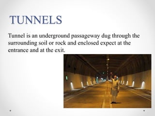
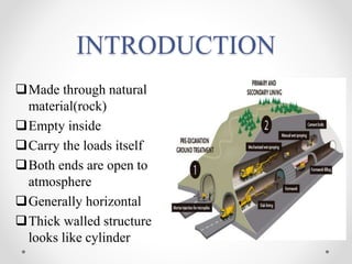
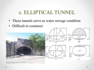
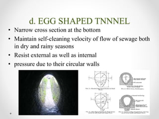
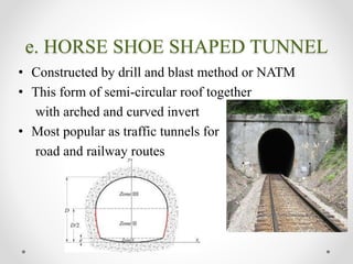
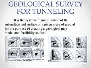
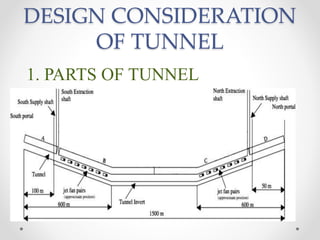
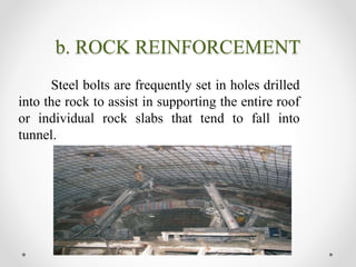
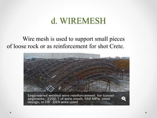
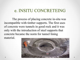
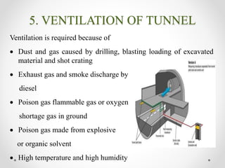
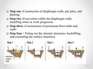
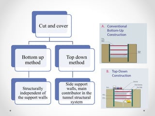
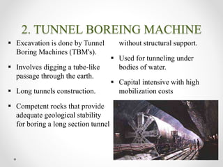
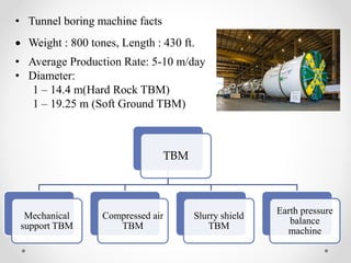
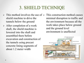
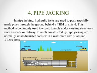
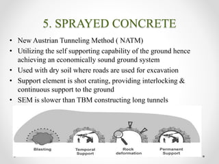
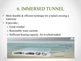
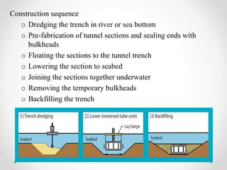
S T J INSTITUTE OF TECHNOLOGY
RANEBENNUR
“TUNNELS CONSTRUCTIONS’’
PRESENTED BY GUIDED BY
VINAY V B HANUMESH B M
8TH SEM B. E (CIVIL) B.E., M.TECH..
ASSITANT PROFESSOR
STJIT, RANEBENNUR STJIT, RANEBENNUR
TUNNELS
Tunnel is an underground passageway dug through the
surrounding soil or rock and enclosed expect at the
entrance and at the exit.
INTRODUCTION
Made through natural
material(rock)
Empty inside
Carry the loads itself
Both ends are open to
atmosphere
Generally horizontal
Thick walled structure
looks like cylinder
PURPOSE OF TUNNEL
• Tunnels are used for highway traffic, railroads
and subways
• To transport water, sewage, oil and gas
• To divert rivers around dam sites while the dam
is being built
• For military and civil defense
FACTORS AFFECTING THE
TUNNEL CONSTRUCTION
• Ground condition
• The groundwater condition
• The length and diameter of tunnel drive
• The depth of tunnel
• The logistics of supporting the tunnel excavation
• The final uses and shape of the tunnel and appropriate
risk
MAJOR TUNNELS OF
THE INDIA
Tunnel name Length of tunnel Tunnel for Situated at
Pir Panjal tunnel 11.2Km long Railway Himalayas
Karbude 6.5Km long Railway Maharashtra
Natuwadi 4.3Km long Railway Mangalore to
Mumbai through
Goa
Chennai Nashri 9.2Km long Roadway Udhampur of
Jammu and
Kashmir
Bhatan 1Km long Roadway Mumbai Pune
expressway
SHAPES OF TUNNEL
a. CIRCULAR TUNNEL
• Constructed using either TBM or drill and blast method
in soft ground
• Greater resistance to
external pressure
• Prefer to carry water and
sewage circulation
b. RECTANGULAR TUNNEL
• They are constructed by cut and cover method or
immersed method or by jacked tunneling
c. ELLIPTICAL TUNNEL
• These tunnels serve as water sewage condition
• Difficult to construct
d. EGG SHAPED TNNNEL
• Narrow cross section at the bottom
• Maintain self-cleaning velocity of flow of sewage both
in dry and rainy seasons
• Resist external as well as internal
• pressure due to their circular walls
e. HORSE SHOE SHAPED TUNNEL
• Constructed by drill and blast method or NATM
• This form of semi-circular roof together
with arched and curved invert
• Most popular as traffic tunnels for
road and railway routes
GEOLOGICAL SURVEY
FOR TUNNELING
It is the systematic investigation of the
subsurface and surface of a given piece of ground
for the purpose of creating a geological map
model and feasibility studies.
DESIGN CONSIDERATION
OF TUNNEL
1. PARTS OF TUNNEL
2. ALIGNMENT
• The road tunnel should be designed in accordance with
the respective manual for geometric design
• The alignment of tunnel must be consistent with there
alignment of the roadway leading to it
• The alignment must consider factors like the sight
distances, minimum turning radius and design speeds
in its design
• Except for maintenance reasons two way roads should
be discouraged in a single tube of tunnel for safety
reasons
3.TUNNEL LINING
• These are the permanent or temporary support for
keeping tunnel from collapse and provide safe.
Tunnel lining are grouped into 3 main forms some
or all of which may be used in construction of
tunnel.
a. Temporary ground support
b. Primary lining
c. Secondary lining
TYPES OF TUNNEL
LINING
a. NATURAL SUPPORT TUNNEL
When the tunnels is being bored through good quality rock.
b. ROCK REINFORCEMENT
Steel bolts are frequently set in holes drilled
into the rock to assist in supporting the entire roof
or individual rock slabs that tend to fall into
tunnel.
c. SHOTCRETE
Pneumatically applied motor and concrete
are increasingly being used for the support of
underground excavation.
d. WIREMESH
Wire mesh is used to support small pieces
of loose rock or as reinforcement for shot Crete.
e. INSITU CONCRETEING
The process of placing concrete in-situ was
incompatible with timber supports. The first uses
of concrete were tunnels in good rock and it was
only with the introduction of steel supports that
concrete became the norm for tunnel lining
material.
4.GROUND WATER CONTROL
Building a dry is a primary concern for tunnel
construction as a dry tunnel provides a safer, friendlier
environment costs. Based on the advanced water proofing
technologies. Today the International Tunneling
Association (ITA) recommends the following infiltration
criteria.
Allowable infiltration
• Tunnel : ≤ 0.002gal/sq. ft./day
• Underground public space : ≤0.001gal/sq. ft./day
5. VENTILATION OF TUNNEL
Ventilation is required because of
 Dust and gas caused by drilling, blasting loading of excavated
material and shot crating
 Exhaust gas and smoke discharge by
diesel
 Poison gas flammable gas or oxygen
shortage gas in ground
 Poison gas made from explosive
or organic solvent
 High temperature and high humidity
6. INVESTIGATION
i. Mapping (Topographic, geologic, etc...)
ii. Geophysical surveying (especially seismic
velocity of rocks)
iii. Trial pits & boreholes
iv. General and local stability analysis
v. Decide to excavation method
CONSTRUCTION
METHODS OF TUNNELING
1.CUT AND COVER
This construction method, whereby the site is fully
excavated, the structure built and then covered over, uses
diaphragm walls as temporary retaining walls within the
site area.
 A shallow place (10-12 m)
 Practical & easier in construction
 May cause traffic problems, noise & dust
 Not Economical if >12 m/dewatering
 Step one :Construction of diaphragm walls, pin piles, and
decking
 Step two :Excavation within the diaphragm walls,
installing struts as work progresses
 Step three :Construction of permanent floor slabs and
walls
 Step four : Fitting out the internal structures, backfilling,
and reinstating the surface structures
Cut and cover
Bottom up
method
Structurally
independent of
the support walls
Top down
method
Side support
walls, main
contributor in the
tunnel structural
system
2. TUNNEL BOREING MACHINE
 Excavation is done by Tunnel
Boring Machines (TBM's).
 Involves digging a tube-like
passage through the earth.
 Long tunnels construction.
 Competent rocks that provide
adequate geological stability
for boring a long section tunnel
without structural support.
 Used for tunneling under
bodies of water.
 Capital intensive with high
mobilization costs
• Tunnel boring machine facts
 Weight : 800 tones, Length : 430 ft.
• Average Production Rate: 5-10 m/day
• Diameter:
1 – 14.4 m(Hard Rock TBM)
1 – 19.25 m (Soft Ground TBM)
TBM
Mechanical
support TBM
Compressed air
TBM
Slurry shield
TBM
Earth pressure
balance
machine
3. SHIELD TECHNIQE
.
 This method involves the use of
shield machine to drive the
tunnels below the ground
 After completion of a work
shaft, the shield machine is
lowered into the shaft and
assembled there before
excavation and construction of
the tunnels using precast
concrete lining segments of
about 1.2 meter width
 This construction method causes
minimal disruption to traffic and
the environment because all the
work takes place below ground
and the ground level
environment is unaffected
4. PIPE JACKING
In pipe jacking, hydraulic jacks are used to push specially
made pipes through the ground behind a TBM or shield. This
method is commonly used to create tunnels under existing structures
such as roads or railway. Tunnels constructed by pipe jacking are
normally small diameter bores with a maximum size of around
3.22m(10ft).
5. SPRAYED CONCRETE
• New Austrian Tunneling Method ( NATM)
• Utilizing the self supporting capability of the ground hence
achieving an economically sound ground system
• Used with dry soil where roads are used for excavation
• Support element is shot crating, providing interlocking &
continuous support to the ground
• SEM is slower than TBM constructing long tunnels
6. IMMERSED TUNNEL
• More feasible & efficient technique for a tunnel crossing a
waterway
• It provides ,
o Good weather
o Reasonable water currents
o Sufficient bearing capacity for riverbed/seabed
Construction sequence
o Dredging the trench in river or sea bottom
o Pre-fabrication of tunnel sections and sealing ends with
bulkheads
o Floating the sections to the tunnel trench
o Lowering the section to seabed
o Joining the sections together underwater
o Removing the temporary bulkheads
o Backfilling the trench
CONCLUSION
• The most governing factor of choice is the soil
conditions
• The safety, level of risk, constructability, speed and
cost
• It is an idea for which every civil engineer must be
proud of
• Implementation of this concept can reduce the amount
of fossil fuel import
• It can save the country’s environment from
deterioration
REFERENCES
• Predicting tunnel squeezing problems in weak heterogeneous
rock masses” Tunnels and Tunneling International Part 1 –
November 2000, Part 2 – December 2000. Evert Hoek and Paul
Marinos
• “construction methods of tunnel”,
https://en.wikipedia.org/wiki/Tunnel_construction
• “design consideration”,
https://en.wikipedia.org/wiki/Tunnel_construction
• “Status of tunneling and underground construction activities
and technologies in India”. R.K.Goel, Central Mining Research
Institute Regional Centre, CBRI, Roorkee 247 667, India. Received
15 March 2001; received in revised form 3 May 2001; accepted 4
May 2001
THANK YOU

Tunnel constructions

  • 1.
    S T JINSTITUTE OF TECHNOLOGY RANEBENNUR “TUNNELS CONSTRUCTIONS’’ PRESENTED BY GUIDED BY VINAY V B HANUMESH B M 8TH SEM B. E (CIVIL) B.E., M.TECH.. ASSITANT PROFESSOR STJIT, RANEBENNUR STJIT, RANEBENNUR
  • 2.
    TUNNELS Tunnel is anunderground passageway dug through the surrounding soil or rock and enclosed expect at the entrance and at the exit.
  • 3.
    INTRODUCTION Made through natural material(rock) Emptyinside Carry the loads itself Both ends are open to atmosphere Generally horizontal Thick walled structure looks like cylinder
  • 4.
    PURPOSE OF TUNNEL •Tunnels are used for highway traffic, railroads and subways • To transport water, sewage, oil and gas • To divert rivers around dam sites while the dam is being built • For military and civil defense
  • 5.
    FACTORS AFFECTING THE TUNNELCONSTRUCTION • Ground condition • The groundwater condition • The length and diameter of tunnel drive • The depth of tunnel • The logistics of supporting the tunnel excavation • The final uses and shape of the tunnel and appropriate risk
  • 6.
    MAJOR TUNNELS OF THEINDIA Tunnel name Length of tunnel Tunnel for Situated at Pir Panjal tunnel 11.2Km long Railway Himalayas Karbude 6.5Km long Railway Maharashtra Natuwadi 4.3Km long Railway Mangalore to Mumbai through Goa Chennai Nashri 9.2Km long Roadway Udhampur of Jammu and Kashmir Bhatan 1Km long Roadway Mumbai Pune expressway
  • 7.
    SHAPES OF TUNNEL a.CIRCULAR TUNNEL • Constructed using either TBM or drill and blast method in soft ground • Greater resistance to external pressure • Prefer to carry water and sewage circulation
  • 8.
    b. RECTANGULAR TUNNEL •They are constructed by cut and cover method or immersed method or by jacked tunneling
  • 9.
    c. ELLIPTICAL TUNNEL •These tunnels serve as water sewage condition • Difficult to construct
  • 10.
    d. EGG SHAPEDTNNNEL • Narrow cross section at the bottom • Maintain self-cleaning velocity of flow of sewage both in dry and rainy seasons • Resist external as well as internal • pressure due to their circular walls
  • 11.
    e. HORSE SHOESHAPED TUNNEL • Constructed by drill and blast method or NATM • This form of semi-circular roof together with arched and curved invert • Most popular as traffic tunnels for road and railway routes
  • 12.
    GEOLOGICAL SURVEY FOR TUNNELING Itis the systematic investigation of the subsurface and surface of a given piece of ground for the purpose of creating a geological map model and feasibility studies.
  • 13.
  • 14.
    2. ALIGNMENT • Theroad tunnel should be designed in accordance with the respective manual for geometric design • The alignment of tunnel must be consistent with there alignment of the roadway leading to it • The alignment must consider factors like the sight distances, minimum turning radius and design speeds in its design • Except for maintenance reasons two way roads should be discouraged in a single tube of tunnel for safety reasons
  • 15.
    3.TUNNEL LINING • Theseare the permanent or temporary support for keeping tunnel from collapse and provide safe. Tunnel lining are grouped into 3 main forms some or all of which may be used in construction of tunnel. a. Temporary ground support b. Primary lining c. Secondary lining
  • 16.
    TYPES OF TUNNEL LINING a.NATURAL SUPPORT TUNNEL When the tunnels is being bored through good quality rock.
  • 17.
    b. ROCK REINFORCEMENT Steelbolts are frequently set in holes drilled into the rock to assist in supporting the entire roof or individual rock slabs that tend to fall into tunnel.
  • 18.
    c. SHOTCRETE Pneumatically appliedmotor and concrete are increasingly being used for the support of underground excavation.
  • 19.
    d. WIREMESH Wire meshis used to support small pieces of loose rock or as reinforcement for shot Crete.
  • 20.
    e. INSITU CONCRETEING Theprocess of placing concrete in-situ was incompatible with timber supports. The first uses of concrete were tunnels in good rock and it was only with the introduction of steel supports that concrete became the norm for tunnel lining material.
  • 21.
    4.GROUND WATER CONTROL Buildinga dry is a primary concern for tunnel construction as a dry tunnel provides a safer, friendlier environment costs. Based on the advanced water proofing technologies. Today the International Tunneling Association (ITA) recommends the following infiltration criteria. Allowable infiltration • Tunnel : ≤ 0.002gal/sq. ft./day • Underground public space : ≤0.001gal/sq. ft./day
  • 22.
    5. VENTILATION OFTUNNEL Ventilation is required because of  Dust and gas caused by drilling, blasting loading of excavated material and shot crating  Exhaust gas and smoke discharge by diesel  Poison gas flammable gas or oxygen shortage gas in ground  Poison gas made from explosive or organic solvent  High temperature and high humidity
  • 23.
    6. INVESTIGATION i. Mapping(Topographic, geologic, etc...) ii. Geophysical surveying (especially seismic velocity of rocks) iii. Trial pits & boreholes iv. General and local stability analysis v. Decide to excavation method
  • 24.
  • 25.
    1.CUT AND COVER Thisconstruction method, whereby the site is fully excavated, the structure built and then covered over, uses diaphragm walls as temporary retaining walls within the site area.  A shallow place (10-12 m)  Practical & easier in construction  May cause traffic problems, noise & dust  Not Economical if >12 m/dewatering
  • 26.
     Step one:Construction of diaphragm walls, pin piles, and decking  Step two :Excavation within the diaphragm walls, installing struts as work progresses  Step three :Construction of permanent floor slabs and walls  Step four : Fitting out the internal structures, backfilling, and reinstating the surface structures
  • 27.
    Cut and cover Bottomup method Structurally independent of the support walls Top down method Side support walls, main contributor in the tunnel structural system
  • 28.
    2. TUNNEL BOREINGMACHINE  Excavation is done by Tunnel Boring Machines (TBM's).  Involves digging a tube-like passage through the earth.  Long tunnels construction.  Competent rocks that provide adequate geological stability for boring a long section tunnel without structural support.  Used for tunneling under bodies of water.  Capital intensive with high mobilization costs
  • 29.
    • Tunnel boringmachine facts  Weight : 800 tones, Length : 430 ft. • Average Production Rate: 5-10 m/day • Diameter: 1 – 14.4 m(Hard Rock TBM) 1 – 19.25 m (Soft Ground TBM) TBM Mechanical support TBM Compressed air TBM Slurry shield TBM Earth pressure balance machine
  • 30.
    3. SHIELD TECHNIQE . This method involves the use of shield machine to drive the tunnels below the ground  After completion of a work shaft, the shield machine is lowered into the shaft and assembled there before excavation and construction of the tunnels using precast concrete lining segments of about 1.2 meter width  This construction method causes minimal disruption to traffic and the environment because all the work takes place below ground and the ground level environment is unaffected
  • 31.
    4. PIPE JACKING Inpipe jacking, hydraulic jacks are used to push specially made pipes through the ground behind a TBM or shield. This method is commonly used to create tunnels under existing structures such as roads or railway. Tunnels constructed by pipe jacking are normally small diameter bores with a maximum size of around 3.22m(10ft).
  • 32.
    5. SPRAYED CONCRETE •New Austrian Tunneling Method ( NATM) • Utilizing the self supporting capability of the ground hence achieving an economically sound ground system • Used with dry soil where roads are used for excavation • Support element is shot crating, providing interlocking & continuous support to the ground • SEM is slower than TBM constructing long tunnels
  • 33.
    6. IMMERSED TUNNEL •More feasible & efficient technique for a tunnel crossing a waterway • It provides , o Good weather o Reasonable water currents o Sufficient bearing capacity for riverbed/seabed
  • 34.
    Construction sequence o Dredgingthe trench in river or sea bottom o Pre-fabrication of tunnel sections and sealing ends with bulkheads o Floating the sections to the tunnel trench o Lowering the section to seabed o Joining the sections together underwater o Removing the temporary bulkheads o Backfilling the trench
  • 35.
    CONCLUSION • The mostgoverning factor of choice is the soil conditions • The safety, level of risk, constructability, speed and cost • It is an idea for which every civil engineer must be proud of • Implementation of this concept can reduce the amount of fossil fuel import • It can save the country’s environment from deterioration
  • 36.
    REFERENCES • Predicting tunnelsqueezing problems in weak heterogeneous rock masses” Tunnels and Tunneling International Part 1 – November 2000, Part 2 – December 2000. Evert Hoek and Paul Marinos • “construction methods of tunnel”, https://en.wikipedia.org/wiki/Tunnel_construction • “design consideration”, https://en.wikipedia.org/wiki/Tunnel_construction • “Status of tunneling and underground construction activities and technologies in India”. R.K.Goel, Central Mining Research Institute Regional Centre, CBRI, Roorkee 247 667, India. Received 15 March 2001; received in revised form 3 May 2001; accepted 4 May 2001
  • 37.