Downloaded 335 times
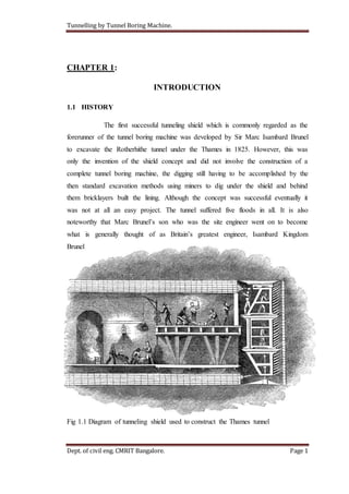
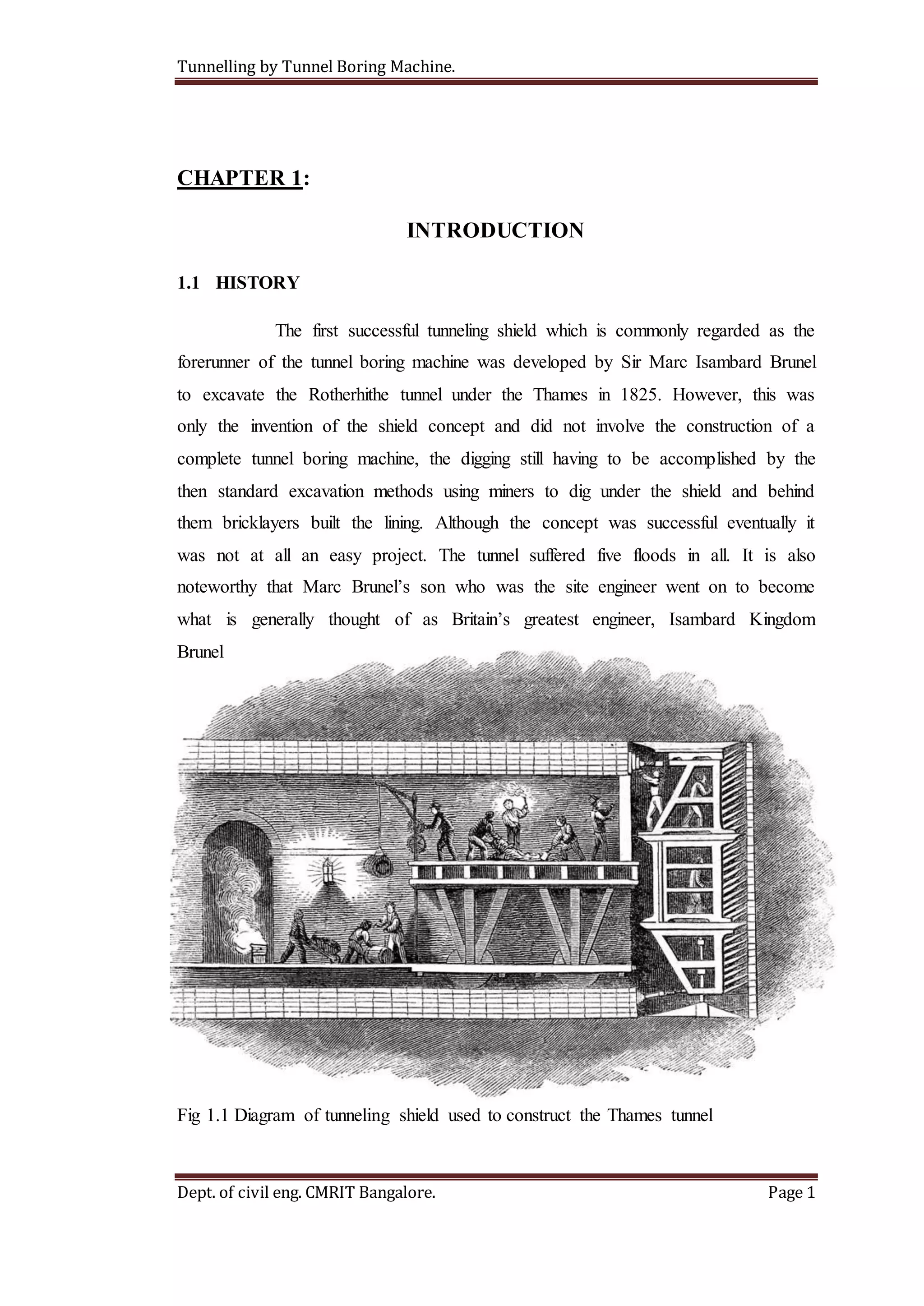

The document provides an overview of tunnel boring machines (TBMs) and their history and use in tunnel construction. Some key points: - The first shield-based tunneling method was developed by Marc Isambard Brunel in 1825 to construct the Thames Tunnel, though miners still did the digging. Later improvements led to round-shaped "tube" tunnels in London. - Early mechanical TBMs in the mid-1800s had limited success digging through rock and shale. The modern breakthrough was the rotating cutting head, based on earlier percussion drills. - TBMs can be specialized for different soil/rock types, using slurry, earth pressure balance, or cutting wheels for rock.


