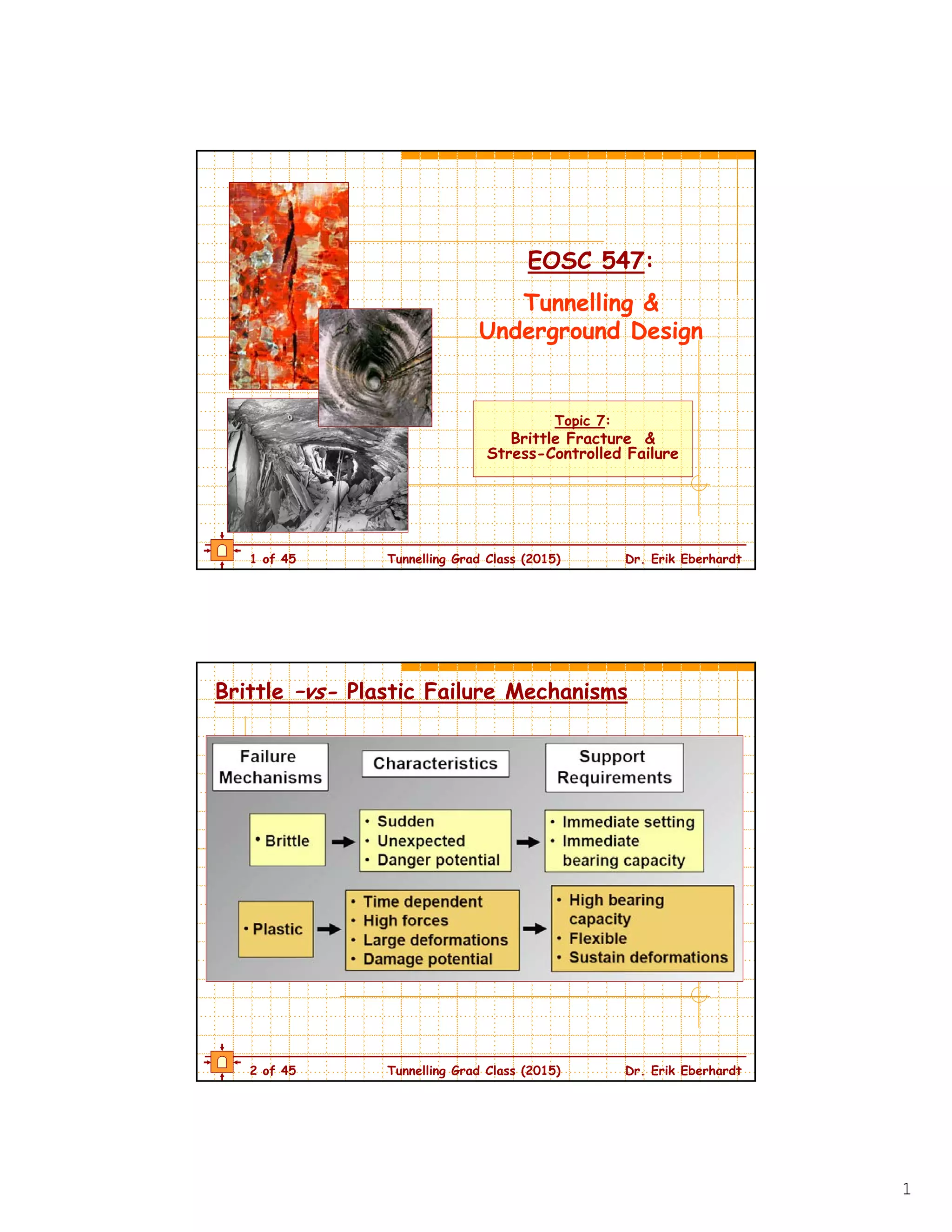
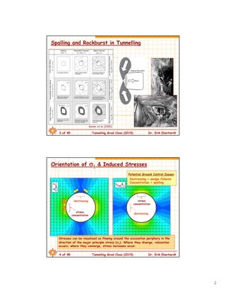
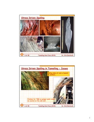
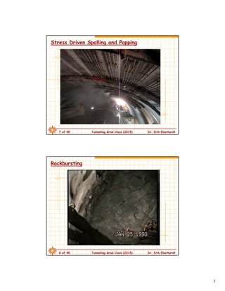
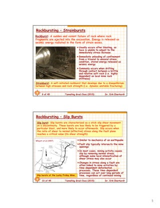
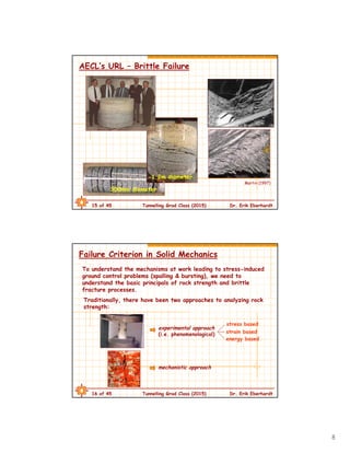
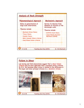
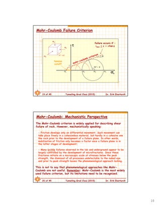
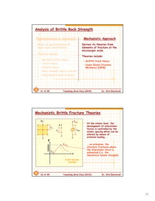
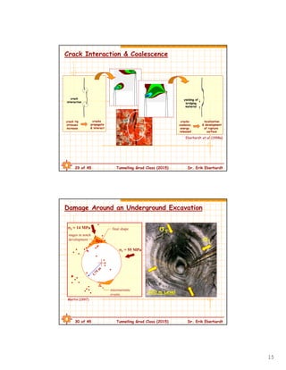
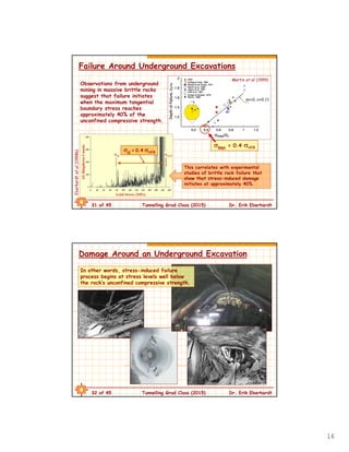
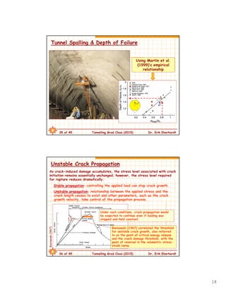
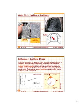
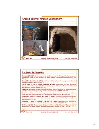
The document discusses brittle fracture and stress-controlled failure in tunneling. It describes how stresses concentrate and relax around underground excavations, which can lead to problems like spalling and rockbursts. Spalling occurs when stresses concentrate and exceed the rock strength, causing slabs or wedges to detach from the tunnel walls or roof. Rockbursts are sudden violent failures caused by the buildup and release of strain energy. The document examines failure mechanisms from both phenomenological and mechanistic perspectives, discussing theories like Mohr-Coulomb criteria and Griffith crack propagation theory. It emphasizes that brittle rock strength is stress-dependent and damage initiates at stresses well below peak strength.
The Gotthard Base Tunnel project in Switzerland faced significant geological uncertainties and challenges during construction. Known risks included water inflows and weak ground conditions in brittle fault zones, squeezing ground in weak rock masses, and potential rockbursts in deep, high-stress sections. Unknown risks that emerged included unexpectedly thick and extensive buried valleys during the construction of the Lötschberg Base Tunnel, which caused a major flood during construction. For the Gotthard Base Tunnel, running ground conditions in water-saturated dolomite formations and the crossing of subhorizontal faults near Faido presented challenges that led to project delays and cost overruns. Addressing these complex geological conditions and unknowns required extensive geological investigations and flexible tunnel construction
This document discusses various tunnelling methods for soft ground, including cut and cover, shield tunnelling using compressed air or slurry, and earth pressure balance tunnelling. Cut and cover involves excavating a trench and placing pre-cast concrete segments, and was used for 75% of the Canada Line project in Vancouver. Shield tunnelling methods provide constant support to the advancing tunnel face. Compressed air shields fell out of favor due to health and safety issues, while slurry shields use bentonite slurry to support the face but require expensive separation plants. Earth pressure balance tunnelling was developed to address limitations of slurry shields, supporting the face through pressure control without slurry or separation plants.
Tunnelling & underground design (Topic5-hard & weak rock tunnelling)Hamed Zarei
The document discusses different methods for excavating tunnels in rock, including drill-and-blast and mechanical excavation using tunnel boring machines (TBMs). Drill-and-blast involves drilling holes, loading them with explosives, and detonating them in a sequence according to a blast design. TBMs can excavate continuously using a rotating cutter head equipped with cutting tools. Factors that influence the performance of each method include rock properties, drilling/cutting rates, tool wear, and downtime. The goal is to optimize the energy used and fragmentation produced during excavation.
Tunnelling & underground design (Topic1-introduction to the tunnelling industry)Hamed Zarei
This document provides an overview of past and present tunnelling projects and challenges. It discusses the stuck Bertha tunnel boring machine in Seattle which has been stuck since 2013 due to overheating. It also discusses cost overruns and litigation on the Seymour-Capilano Twin Tunnels project in BC. Finally, it provides details on the course topics, lectures, and assignments for an introduction to tunnelling class.
The document discusses the New Austrian Tunnelling Method (NATM) for excavating tunnels in weak rock. Some key points of the NATM include: (1) controlling ground deformations by applying early temporary support like rock bolts and shotcrete, (2) using flexible support that deforms with the ground, and (3) closing the tunnel invert quickly to form a load-bearing ring. The NATM also emphasizes monitoring ground movements and revising support as needed to maintain stability. While economical by matching support to conditions, the NATM requires cooperation between engineers to determine daily support requirements.
1. The document discusses various terminology used for underground structures related to excavation such as adits, tunnels, shafts, chambers, and portals.
2. It also discusses tunnel construction methods like shield tunneling and cut-and-cover tunneling as well as tunnel boring machines (TBMs).
3. Key challenges with underground excavations discussed include rock falls, rock bursts, squeezing ground, and ensuring long-term stability, especially in challenging ground conditions.
Tunnelling & underground design (Topic3-geotechnical data baseline reports)Hamed Zarei
This document discusses risk management in tunneling projects. It begins by providing context on managing hazards in tunneling projects such as contractual disputes, unforeseen conditions, and equipment failures. It then discusses how contracts are used to manage financial risk and trends toward design-build contracts with tight schedules and budgets. An example is given of the St. Gotthard tunnel project that went over budget and late due to pressure to meet deadlines. The document outlines the risk management process of identifying hazards, analyzing probability and consequences, evaluating risk, and implementing risk reduction measures. It discusses owner-contractor roles and responsibilities in risk management as well as types of tunneling contracts and approaches to construction delivery such as design-build. The document concludes
In mining operations, blasting has become a routine work. With proper understanding of the rocks and blasting methods, the mining work can be done effectively. This module explains the rock blasting methods adopted in mining industries.
Drilling and blasting involves different types of drilling like rotary and percussive drilling. Rotary drilling uses tricone bits and drag bits while percussive uses hammers. Factors like burden, spacing, stemming affect blast design. Explosives like TNT, dynamite and safety fuses are used. Blasted rocks undergo processes like radial cracking and flexural rupture. Controlled blasting techniques like presplitting and cushion blasting reduce overbreak. Explosives have risks but when used properly can efficiently fracture rocks for excavation.
NATM (New Austrian Tunneling Method ) in TunnelingHamed Zarei
1. NATM (New Austrian Tunneling Method) is a flexible tunneling method that utilizes shotcrete, wire mesh, rock bolts, and lattice girders for tunnel support. It mobilizes the strength of the rock mass and uses dynamic design that adapts the support based on rock conditions.
2. Excavation in NATM progresses from top heading to benches in poor rock. It is done in small sequential cells to support unstable ground. Primary lining of shotcrete is applied immediately after excavation.
3. Rock mass is classified using methods like RQD, RMR, and Q-factor to determine appropriate support. Flexible shotcrete and bolting allow adaptation to changing geology encountered during tunnel
A Review Study on Methods of Tunneling in Hard Rocksijsrd.com
This article presents a review on the different methodologies that are used for tunnels excavations in hard rocks in present era. Growing needs for modern transportation and utility networks have increased the demand for a more extensive and elaborate use of underground space or through high mountains / hills. As a result, more projects have to be completed in various ground conditions and one of which is more challenging is to carry out excavation work in hard rocks. Significant technological advances have rendered these projects possible, but have also given rise to new challenges as many of these projects have to be completed in difficult conditions, with very strict environmental constraints, particularly in urban areas where the potential impact of tunneling on existing structures is a major concern. This paper addresses the main aspects of tunneling and underground works performed in hard rocks. A summary is presented of the more recent advances and widely adopted techniques in these regards.
Drilling is the process of making holes into hard surfaces like rock. In surface mining, drilling is used for blast hole drilling, core drilling for exploration, and technical drilling. Rotary blast hole drilling involves rotating drill pipes to which a bit is attached to break up rock. The main assemblies of a rotary drill rig include the mast, rod changer, rotary head, pull down mechanism, air compressor, drill pipes, hydraulic system, and dust control components.
Seismic Response of Multi storey Flat Slab Building with and without Shear WallIRJET Journal
This document summarizes a research study that analyzed the seismic response of a 20-story flat slab building (G+19) with and without shear walls through dynamic time history analysis using ETABS software. Four models were analyzed: 1) a flat slab building without shear walls, 2) a flat slab building with a shear wall in the building core, 3) a flat slab building with shear walls at the building corners, and 4) a flat slab building with shear walls at the side centers of the perimeter boundary. The study found that the addition of shear walls improved the building's lateral resistance and reduced displacements and drifts compared to the flat slab building without shear walls. The most effective configuration was the flat slab building with a
Optimisation of drilling and blasting focussing on fly rockSafdar Ali
This document discusses optimizing drilling and blasting to minimize fly rock in surface mining. Fly rock, which is rock propelled from the blast area, is a major safety hazard and cause of accidents. The document reviews factors that influence fly rock like burden, stemming, charging, and geology. It presents three models for predicting maximum fly rock distance and discusses field data collection and analysis from limestone quarry blasts to validate the models. Recommendations are provided to control fly rock through improved blast design, site controls, crew experience, and covering exposed areas.
PPT on execution of 680 m long tunnel ensuring safety of the adjoining rail t...Rajesh Prasad
The said paper by Rajesh Prasad Executive Director RVNL has been published in IPWE international seminar held on 23/24-02-2018. The power point presentation nicely explains about how the technical challenges and administrative challenges addressed in completion of the tunnel while constructing a tunnel by the side of a railway tunnel with train operation in place and the entire area is affected by LWE activities.
This document provides information about drilling and blasting techniques used at Suez Cement quarries. It discusses drilling methods, including rotary and rotary percussion drilling. It also covers topics like blast hole patterns, burden calculations, deviation control, and factors that affect drilling and blasting performance. The document then discusses explosive types like ANFO, emulsion, and dynamite used in quarry blasting and compares their properties.
The document outlines the different types and construction methods of tunnels. It discusses tunnels constructed through hard rock versus soft rock/soil, and lists the specific steps and techniques used for each. These include erecting supports, drilling, explosives, ventilation, muck removal, reinforcement, concrete lining, full face/heading and benching/drift/pilot tunnel/perimeter methods for hard rock, and fore poling/needle beam/lines plate/shield methods for soft ground. The document provides an overview of tunnel construction processes based on the material being tunneled through.
tunnel lining may be permanent or temporary based upon their use and requirement. design of lining is done in two parts one is temporary or initial lining design and other is permanent design of the lining. empirical and theoretical methods are major design methods.
Firing patterns and its effect on muckpile shape parameters and fragmentation...eSAT Journals
Abstract Proper use of firing pattern vis-à-vis the blast requirements can provide optimal blast performance in terms of fragmentation, throw, wall control etc. This is largely attributed to the importance of firing burden in any blast round. By changing the firing patterns the firing burden, and, thereby the ratio of spacing to burden is also subject to change. Proper initiation timing is as important for fragmentation as the burden, spacing, sub drilling, stemming etc. Simultaneous initiation leads to the problems, such as, coarser fragmentation, blasting of a large number of holes at a given time which leads to the other problems. The present research study which was conducted in three limestone quarries where major problems such as of improper fragmentation, poor wall control, and poor heave characteristics of the muckpile were observed. Designed firing pattern was not able to provide the requisite fragmentation, and, even the throw. Modifications in firing pattern were implemented to obtain the required blast results. Keywords: Firing pattern, fragmentation, progressive relief, throw, drop, muckpile
This document outlines standard operating procedures for secondary blasting at a mine site in Sierra Leone. It describes two methods of secondary blasting - popping and plaster/mud blasting. The procedure highlights how to safely conduct popping for boulder and toe blasting. It details steps for preparation, marking, drilling, charging, stemming, and firing of boulders and toes. Guidelines are provided for determining blasthole positions, depths, and explosive charges based on the size and geometry of boulders and average depths of toes. The objective is to break oversized rocks and toes using the minimum explosive charge while minimizing risks of airblast and flyrocks.
tunnelling scope, construction techniques and necessityShashank Gaurav
This document discusses tunnel construction methods and planning. It describes the main types of tunnels based on application and construction method. The key construction methods covered are cut-and-cover, pipe jacking, shield tunneling, New Austrian tunneling method, and immersed tube tunneling. For each method, the document outlines the construction sequence, advantages, and disadvantages. Proper planning stages including investigations and alignment selection are also emphasized.
The Evolution of Sublevel Caving at Trojan Mine, Bindura, Zimbabwe, J G TaylorJohn Guy Taylor
Several technical and economic factors have to be taken into
consideration in developing an optimal mining method. This paper
describes some of the important factors learnt during the evolution of the
sub-level cave mining method at Trojan Nickel Mine, part of the Bindura
Nickel Corporation (BNC) in Zimbabwe.
Buffer blasting presentation for Coal 2016.rev1John Latilla
Targeted buffer blasting is used at Ukhaa Khudag coal mine in Mongolia to stabilize slopes containing bedding plane shears by disrupting the shear planes. Buffer blasts increase slope stability by raising the cohesion and friction angle of the rock mass. Analysis shows buffer blasting can allow slopes up to 13 degrees above the dip of the coal seams. Of the cases studied, 86% of buffer blasts successfully stabilized slopes. Improved planning is needed to proactively identify areas needing buffer blasts.
The document provides details on executing tunnel drives using the New Austrian Tunneling Method (NATM) in Manipur, India. It describes the various support elements of NATM including forepoling, drilling, blasting, mucking, shotcreting, installing wire mesh and lattice girders, and systematic rock bolting. A typical drive sequence is also outlined, beginning with forepoling installation and ending with rock bolting after two layers of shotcrete have been applied. The document emphasizes controlling deformation, stabilizing the surrounding rock mass, and providing flexible but active support during tunnel drives when using the NATM approach.
The document provides an overview of the "Cut-and-Cover" and "Cover-and-Cut" tunnel construction techniques. The "Cut-and-Cover" method involves excavating a trench and constructing the tunnel structure within it, then refilling the trench. The "Cover-and-Cut" method first constructs a retaining concrete shell, then excavates underneath it for tunnel construction. Both methods are used for highway and railway tunnels where shallow depths or unstable ground conditions require extra support during construction. The document discusses the design process and construction steps for each method.
The document discusses the design of pillars in underground coal mining. It notes that pillar failure can be gradual or sudden, with sudden failures causing disasters. Statutory guidelines exist for pillar dimensions but have limitations. The author proposes a modified formula to calculate pillar load that includes a dynamic load factor to account for loads during pillar extraction. Pillar strength is typically estimated using empirical formulas that the author critiques. The author suggests experience and site conditions be considered to better estimate pillar strength for ensuring stability of underground workings.
This document provides information about tunnel construction using the New Austrian Tunneling Method (NATM). It discusses the various steps of NATM tunneling including drilling, blasting, mucking, shotcreting, installing lattice girders and rock bolts, and ventilation. NATM is advantageous for tunneling in soft ground as it monitors rock deformation and designs support structures accordingly. The document outlines the typical sequence of NATM tunnel construction and importance of factors like geology and ventilation.
This document discusses how different explosive energies used in blasting can influence the strength of resulting rock fragments and the throughput of a SAG mill. Experimental studies found that higher explosive energies produced weaker rock fragments through cracking and damage. To validate this, granite samples were blasted using explosives with different velocities and the fragments were tested. Comminution parameters showed the fragments were weaker when higher energies were used. Modelling found this pre-conditioning of fragments could increase SAG mill throughput by up to 20%.
Mohamed Abd Rabo Selmy Hassan is an accounting professional with extensive experience in accounts receivables, accounts payables, cash management, audit, and financial reporting. He has over 10 years of experience working in roles such as senior accountant, billing accountant, and chief accountant in Egypt and Saudi Arabia. He holds a Bachelor of Commerce degree in accounting from Suez Canal University.
numerical study and analytical solution of P-wave attenuation insensitive und...Hamed Zarei
1) The document analyzes P-wave attenuation in underground rock structures through both analytical and numerical methods.
2) Analytical and numerical results show that any vacuum or cavity in rock mass greatly increases P-wave attenuation, while rock material with mechanical strength properties in a virtual space decreases attenuation and increases wave energy transmission.
3) Key parameters analyzed include the density and properties of virtual spaces and joints, and results show that factors like cavity thickness and density contrast have significant effects on wave attenuation.
This document discusses tools and equipment used for railway track maintenance. It outlines the objectives of maintenance to prolong the life of tracks and rolling stock and increase safety. Good maintenance allows for higher train speeds, fuel savings, and more passenger usage. Tracks require maintenance due to deterioration from train loads, weathering, and curvature effects. Maintenance includes daily checks using hand tools and periodic rebuilding every 2-3 years using both hand tools and mechanical equipment like lifting jacks and tampers to realign tracks, level ballast, and replace worn components like crossings and tunnels. Common hand tools are rail gauges, spanners, picks, shovels and levels, while mechanical tools help lift and align larger sections of track.
This document provides an overview of tunnels, including their definition, history, construction methods, design considerations, and effects of earthquakes. Tunnels are underground passages constructed for various purposes like transportation. Key construction methods include cut-and-cover, drill-and-blast, bored tunneling using a Tunnel Boring Machine, and sequential excavation. Design requires considering factors like ground conditions, water management, tunnel usage, and seismic activity. During earthquakes, tunnels can experience ground shaking, ground failures, deformations, cracking, and other effects that must be addressed in seismic design. The Gotthard Base Tunnel case study exemplifies addressing geological challenges during tunnel construction.
This document discusses submerged floating tunnels, which are tunnels that float underwater at a certain depth below the surface. It provides details on how submerged floating tunnels work based on Archimedes' principle of buoyancy. The tunnels are made of multiple layers including aluminum, foam, and concrete to resist saltwater corrosion and provide strength. Construction involves precasting tunnel segments, transporting them underwater, joining them with rubber gaskets, and anchoring them to cables attached to foundations on the seafloor. Advantages are provided such as allowing transportation routes in extremely deep waters and reducing environmental impacts. A transatlantic tunnel connecting North America and Europe is proposed as an example project.
Tunnel making methods and tunnel boring machine mohammadsalikali
The document discusses various tunnel construction methods. It begins with an introduction to tunnels and their purposes. It then covers traditional/classical methods that were used until the late 19th century such as the English, German, and Austrian systems which involved hand excavation and timber supports. More modern methods discussed include cut-and-cover, drill-and-blast, tunnel boring machines (TBMs), immersed tunnels, and tunnel jacking. Factors in choosing a method include geological conditions, tunnel size/length, surface impacts, and construction speed/costs.
A submerged tunnel floats underwater, supported by buoyancy, with cables anchoring it to prevent floating up or sinking down. It has advantages over bridges such as being lighter and experiencing less stress during earthquakes. Submerged tunnels can be constructed by dredging a trench, casting tunnel elements, transporting them to the site, and lowering them into place before sealing the joints and backfilling over top. While requiring specialized marine construction, the technique is often less risky than other tunneling methods and allows for faster construction between shores.
The document discusses various aspects of tunnel engineering. It begins by introducing tunnels and their uses for transportation. It then discusses the Thames Tunnel in London as an example. The document outlines several advantages of tunneling over other methods. It also discusses considerations for selecting tunnel routes and economies of tunneling. The remainder of the document describes various tunneling methods through both rock and soft ground, as well as tunnel drainage, lighting, ventilation, lining, and maintenance.
The document discusses fracture toughness and fatigue testing of engineering materials. It defines fracture toughness as a material's resistance to brittle fracture when a crack is present. The key parameters used to calculate fracture toughness are the applied load constant, material critical stress, and length of the crack surface. It also discusses different types of fatigue testing including high-cycle, low-cycle, and thermal fatigue. Impact testing measures a material's ability to resist deformation from sudden loading and describes Charpy, Izod, drop-weight, and dynamic tear impact tests.
- Fracture is the separation of an object into pieces due to stress. There are two main types: ductile fracture and brittle fracture.
- Ductile fracture involves plastic deformation and occurs through processes like necking and the formation and coalescence of microvoids. It results in a cup-and-cone pattern. Brittle fracture occurs suddenly without plastic deformation.
- Fracture mechanics studies how cracks propagate in materials. The Griffith theory and models like the Mohr-Coulomb criterion describe how stresses lead to fracture based on factors like crack size and material properties.
fracture mechanics and damage tolerance .Why do high strain rate, low temperature and triaxial state of stress promote brittle fracture?Method of Crack/Crack Like Defect Analysis
Component failure in road traffic accident by ayoub el amriAyoub Elamri
This document discusses various failure modes in materials including brittle versus ductile fracture, fatigue, creep, and stress concentration effects. It explains that brittle materials fracture with little deformation while ductile materials undergo extensive plastic deformation before fracturing. Fatigue failure can occur with fluctuating stresses and involves crack initiation and propagation. Creep is time-dependent deformation that increases with stress and temperature. Stress concentrators like defects and notches reduce a material's strength significantly and can initiate cracks. The document provides examples and diagrams to illustrate different failure mechanisms.
This document provides an overview of fracture mechanics. It discusses brittle and ductile fracture, the three modes of failure, energy release rate and crack resistance parameters like the J-integral and stress intensity factor. It also covers crack growth, applications of fracture mechanics like designing and material selection, and explains concepts such as the critical stress intensity factor and T-stress in less than three sentences.
Fatigue occurs when a structure is subjected to fluctuating stresses from repeated loads, which can cause cracks to form and propagate even when stresses are much lower than the material's static strength. There are three main stages of fatigue: crack initiation at stress concentrators, incremental crack propagation, and rapid crack propagation once a critical crack size is reached. The total fatigue life consists of the number of cycles for crack initiation and propagation. Fatigue life depends on factors like stress range, structural detail, material properties, and environment. Design of structures against fatigue involves comparing stress ranges to the fatigue strength of detail categories according to EN 1993-1-9.
Failure analysis can be defined as studying how and why materials fail. It aims to understand failure modes to avoid future disasters. Ceramics and glasses typically fail in a brittle manner due to their inherent brittleness and use at high temperatures. Their fracture behavior differs from metals. Metals can fail in either brittle or ductile modes depending on temperature, with body-centered cubic alloys being brittle at low temperatures and face-centered cubic alloys tending to be ductile. Fatigue failure occurs when repeated cyclic loading below a material's tensile strength creates cracks that grow and reduce load capacity over increasing cycles. Fracture mechanics analyzes failure in structurally flawed materials, with fracture toughness characterizing a material
The document discusses two main mechanisms of plastic deformation: slip and twinning. Slip occurs when one part of a crystal moves over another along specific crystallographic planes and directions. Twinning results when a portion of a crystal takes on a symmetrical orientation to the rest of the crystal, dividing it into two mirrored regions. Factors like external loads, crystal structure, and orientation influence whether slip or twinning occurs. The document also covers different types of material failure like ductile fracture, brittle fracture, creep, and fatigue.
This Report presents a review of the definition of the equivalent crack concept by defining the relationship between two correlated theories, which are fracture mechanics and damage mechanics based on Mazars static damage model and derived in the framework of the thermodynamics of irreversible processes, an energetic equivalence between the two descriptions is proposed. This paper also presents an example of combined damage and fracture calculation on a concrete specimen, the energy consumption during crack propagation, modelled with damage mechanics, is computed. Finally, the paper provide a comparison for the fracture energy according to the damage model with experiments and linear elastic fracture mechanics
The document discusses three main types of material failure: fatigue failure, failure under fluctuating stress, and creep failure. Fatigue failure occurs when a material breaks under cyclic stresses that are lower than the material's static load capacity. Creep failure happens at high temperatures over long periods of time due to constant stresses. The key factors that influence fatigue life and creep behavior include stress levels, temperature, surface quality, microstructure, and environment. Crack initiation and propagation play an important role in fatigue failure. Different creep mechanisms dominate depending on the material, stress levels, and temperature.
This document provides an introduction to fracture mechanics from Ozen Engineering Inc. It discusses key fracture mechanics concepts like stress intensity factors, J-integrals, and cohesive zone modeling. It also outlines Ozen's fracture mechanics training sessions which will cover topics like linear elastic fracture mechanics analysis in ANSYS, extended finite element modeling, and fatigue crack propagation modeling.
This document discusses toughness and fracture toughness testing. It defines toughness as the energy absorbed by a material until fracture. Common toughness tests include the Charpy and Izod impact tests, which measure the energy absorbed during a high-velocity impact. However, these tests do not provide data needed for designing with cracks and flaws. Fracture toughness is a better property for design, as it indicates the stress required to propagate a preexisting flaw. The document outlines fracture toughness testing methods like compact tension and single edge notch bending specimens. It also discusses factors that influence fracture toughness values like material thickness, grain orientation, and plane strain versus plane stress conditions.
The document discusses linear elastic fracture mechanics (LEFM) concepts used for fatigue crack growth analysis and damage tolerant design. It covers key topics such as:
- Stress intensity factor (K), which quantifies crack tip stress fields.
- Fatigue crack growth rate (da/dN) relationships with the stress intensity factor range (ΔK), following a sigmoidal curve with three distinct regions.
- Mean stress effects on fatigue crack growth, with increased mean stress generally increasing growth rates.
- Fracture toughness (Kc, KIc) and its relationship to crack size and specimen thickness.
- Limitations of LEFM for cases with high plasticity or small cracks relative to
This document provides an overview of fracture mechanics, including the different modes of crack surface displacement, types of fracture such as brittle and ductile, linear elastic fracture mechanics concepts, plasticity considerations, design philosophies like fail-safe and safe-life, environmental effects like stress corrosion cracking, and applications to aircraft structural design and analysis. It also discusses methods to simulate cracks using finite element analysis and compare materials' fracture properties.
Fault'classification of fault and mechanism of faultingShivam Jain
This document summarizes a seminar on faults presented by Aditi Jena to her professor. It defines a fault as a fracture in rock across which there is significant displacement. Faults are classified based on their dip, pattern of movement, and stress conditions. The main types are normal faults which form during tension, reverse/thrust faults during compression, and strike-slip faults when the intermediate stress axis is vertical. Fault planes develop at 30 degrees to the maximum stress and slip occurs perpendicular to the intermediate stress. Examples like the San Andreas fault and Main Central Thrust are given to illustrate different fault types.
This document discusses the importance of geomechanics in understanding unconventional reservoirs. It covers topics such as natural fractures, mechanical rock properties, stress regimes, and how they impact horizontal drilling, hydraulic fracturing, and reservoir productivity. Natural fractures are especially important in tight formations as they can provide permeability and introduce anisotropy. The document also provides classifications of fractured reservoirs and naturally occurring fractures.
Similar to Tunnelling & underground design (Topic7-brittle failure) (20)
This document discusses blasting rock through the use of explosives. It provides an overview of blast design and the types of explosives commonly used, including dynamite, slurries, and ANFO. It explains concepts like burden, stemming, and delay devices. The goal of the document is to provide guidance on designing blast hole layouts and calculating explosive amounts for effective blasting of rock.
Intelligent back analysis using data from the instrument (poster)Hamed Zarei
This document presents a model using artificial neural networks for back analysis of tunnel monitoring data from the Chehel Chai water conveyance tunnel in Iran. Input data from 27 parameters across 3 categories were used to train a neural network model on results from 18 convergence stations. The trained model was then able to accurately estimate rock mass elasticity and in situ stress values based on new monitoring data, demonstrating its effectiveness for intelligent back analysis of future tunnel monitoring results.
Modeling of twain Tunnel water conveyanceHamed Zarei
1. The document discusses creating a tunnel model using PLAXIS software, including defining the geometry, material properties, and boundary conditions of the tunnel and surrounding rock.
2. A horseshoe-shaped tunnel with a diameter of 5.3m and space of 12m between tunnels is modeled. Rock and shotcrete material properties are input along with standard earthquake boundary conditions.
3. Dynamic analysis is performed by applying a prescribed displacement at the bottom boundary and vertical harmonic load to model an earthquake, with results viewed in output graphs.
Adaptive synchronous sliding control for a robot manipulator based on neural ...IJECEIAES
Robot manipulators have become important equipment in production lines, medical fields, and transportation. Improving the quality of trajectory tracking for
robot hands is always an attractive topic in the research community. This is a
challenging problem because robot manipulators are complex nonlinear systems
and are often subject to fluctuations in loads and external disturbances. This
article proposes an adaptive synchronous sliding control scheme to improve trajectory tracking performance for a robot manipulator. The proposed controller
ensures that the positions of the joints track the desired trajectory, synchronize
the errors, and significantly reduces chattering. First, the synchronous tracking
errors and synchronous sliding surfaces are presented. Second, the synchronous
tracking error dynamics are determined. Third, a robust adaptive control law is
designed,the unknown components of the model are estimated online by the neural network, and the parameters of the switching elements are selected by fuzzy
logic. The built algorithm ensures that the tracking and approximation errors
are ultimately uniformly bounded (UUB). Finally, the effectiveness of the constructed algorithm is demonstrated through simulation and experimental results.
Simulation and experimental results show that the proposed controller is effective with small synchronous tracking errors, and the chattering phenomenon is
significantly reduced.
We have compiled the most important slides from each speaker's presentation. This year’s compilation, available for free, captures the key insights and contributions shared during the DfMAy 2024 conference.
CHINA’S GEO-ECONOMIC OUTREACH IN CENTRAL ASIAN COUNTRIES AND FUTURE PROSPECTjpsjournal1
The rivalry between prominent international actors for dominance over Central Asia's hydrocarbon
reserves and the ancient silk trade route, along with China's diplomatic endeavours in the area, has been
referred to as the "New Great Game." This research centres on the power struggle, considering
geopolitical, geostrategic, and geoeconomic variables. Topics including trade, political hegemony, oil
politics, and conventional and nontraditional security are all explored and explained by the researcher.
Using Mackinder's Heartland, Spykman Rimland, and Hegemonic Stability theories, examines China's role
in Central Asia. This study adheres to the empirical epistemological method and has taken care of
objectivity. This study analyze primary and secondary research documents critically to elaborate role of
china’s geo economic outreach in central Asian countries and its future prospect. China is thriving in trade,
pipeline politics, and winning states, according to this study, thanks to important instruments like the
Shanghai Cooperation Organisation and the Belt and Road Economic Initiative. According to this study,
China is seeing significant success in commerce, pipeline politics, and gaining influence on other
governments. This success may be attributed to the effective utilisation of key tools such as the Shanghai
Cooperation Organisation and the Belt and Road Economic Initiative.
A review on techniques and modelling methodologies used for checking electrom...nooriasukmaningtyas
The proper function of the integrated circuit (IC) in an inhibiting electromagnetic environment has always been a serious concern throughout the decades of revolution in the world of electronics, from disjunct devices to today’s integrated circuit technology, where billions of transistors are combined on a single chip. The automotive industry and smart vehicles in particular, are confronting design issues such as being prone to electromagnetic interference (EMI). Electronic control devices calculate incorrect outputs because of EMI and sensors give misleading values which can prove fatal in case of automotives. In this paper, the authors have non exhaustively tried to review research work concerned with the investigation of EMI in ICs and prediction of this EMI using various modelling methodologies and measurement setups.
Low power architecture of logic gates using adiabatic techniquesnooriasukmaningtyas
The growing significance of portable systems to limit power consumption in ultra-large-scale-integration chips of very high density, has recently led to rapid and inventive progresses in low-power design. The most effective technique is adiabatic logic circuit design in energy-efficient hardware. This paper presents two adiabatic approaches for the design of low power circuits, modified positive feedback adiabatic logic (modified PFAL) and the other is direct current diode based positive feedback adiabatic logic (DC-DB PFAL). Logic gates are the preliminary components in any digital circuit design. By improving the performance of basic gates, one can improvise the whole system performance. In this paper proposed circuit design of the low power architecture of OR/NOR, AND/NAND, and XOR/XNOR gates are presented using the said approaches and their results are analyzed for powerdissipation, delay, power-delay-product and rise time and compared with the other adiabatic techniques along with the conventional complementary metal oxide semiconductor (CMOS) designs reported in the literature. It has been found that the designs with DC-DB PFAL technique outperform with the percentage improvement of 65% for NOR gate and 7% for NAND gate and 34% for XNOR gate over the modified PFAL techniques at 10 MHz respectively.
ACEP Magazine edition 4th launched on 05.06.2024Rahul
This document provides information about the third edition of the magazine "Sthapatya" published by the Association of Civil Engineers (Practicing) Aurangabad. It includes messages from current and past presidents of ACEP, memories and photos from past ACEP events, information on life time achievement awards given by ACEP, and a technical article on concrete maintenance, repairs and strengthening. The document highlights activities of ACEP and provides a technical educational article for members.
HEAP SORT ILLUSTRATED WITH HEAPIFY, BUILD HEAP FOR DYNAMIC ARRAYS.
Heap sort is a comparison-based sorting technique based on Binary Heap data structure. It is similar to the selection sort where we first find the minimum element and place the minimum element at the beginning. Repeat the same process for the remaining elements.
Advanced control scheme of doubly fed induction generator for wind turbine us...IJECEIAES
This paper describes a speed control device for generating electrical energy on an electricity network based on the doubly fed induction generator (DFIG) used for wind power conversion systems. At first, a double-fed induction generator model was constructed. A control law is formulated to govern the flow of energy between the stator of a DFIG and the energy network using three types of controllers: proportional integral (PI), sliding mode controller (SMC) and second order sliding mode controller (SOSMC). Their different results in terms of power reference tracking, reaction to unexpected speed fluctuations, sensitivity to perturbations, and resilience against machine parameter alterations are compared. MATLAB/Simulink was used to conduct the simulations for the preceding study. Multiple simulations have shown very satisfying results, and the investigations demonstrate the efficacy and power-enhancing capabilities of the suggested control system.
1. 1
1 of 45 Tunnelling Grad Class (2015) Dr. Erik Eberhardt
EOSC 547:
Tunnelling &
Underground Design
Topic 7:
Brittle Fracture &
Stress-Controlled Failure
2 of 45 Tunnelling Grad Class (2015) Dr. Erik Eberhardt
Brittle –vs- Plastic Failure Mechanisms
2. 2
3 of 45 Tunnelling Grad Class (2015) Dr. Erik Eberhardt
Spalling and Rockburst in Tunnelling
Kaiser et al. (2000)
4 of 45 Tunnelling Grad Class (2015) Dr. Erik Eberhardt
Orientation of 1 & Induced Stresses
1
destressing
stress
concentration
1
destressing
stress
concentration
Potential Ground Control Issues:
Destressing = wedge failures
Concentration = spalling
Stresses can be visualized as flowing around the excavation periphery in the
direction of the major principle stress (1). Where they diverge, relaxation
occurs; where they converge, stress increases occur.
3. 3
5 of 45 Tunnelling Grad Class (2015) Dr. Erik Eberhardt
Stress Driven Spalling
6 of 45 Tunnelling Grad Class (2015) Dr. Erik Eberhardt
Stress Driven Spalling in Tunnelling - Issues
Falling slabs of rock a hazard
to workers.
Problem for TBM as gripper pads cannot
be seated on the side wall.
4. 4
7 of 45 Tunnelling Grad Class (2015) Dr. Erik Eberhardt
Stress Driven Spalling and Popping
8 of 45 Tunnelling Grad Class (2015) Dr. Erik Eberhardt
Rockbursting
5. 5
9 of 45 Tunnelling Grad Class (2015) Dr. Erik Eberhardt
Rockbursting – Strainbursts
Rockburst: A sudden and violent failure of rock where rock
fragments are ejected into the excavation. Energy is released as
seismic energy radiated in the form of strain waves.
Strainburst: A self-initiated rockburst that develops due to a disequilibrium
between high stresses and rock strength (i.e. dynamic unstable fracturing).
Usually occurs after blasting, as
face is unable to adjust to the
immediately stress increase
Immediate unloading of confinement
from a triaxial to uniaxial stress
condition, stored energy released as
seismic energy
Commonly occurs when drifting
through contact between a brittle
and relative soft rock (i.e. highly
dependent on local mine rock
stiffness)
10 of 45 Tunnelling Grad Class (2015) Dr. Erik Eberhardt
Rockbursting – Slip Bursts
Slip burst: Slip bursts are characterized as a stick-slip shear movement
on a discontinuity. These bursts are less likely to be triggered by a
particular blast, and more likely to occur afterwards. Slip occurs when
the ratio of shear to normal (effective) stress along the fault plane
reaches a critical value (its shear strength).
Slip bursts at the Lucky Friday Mine.
Similar to mechanics of an earthquake
Fault slip typically intersects the mine
openings
In most cases, mining activity causes
slip by removing normal stress,
although some local intensification of
shear stress may also occur
Changes in stress along a fault are
often linked to mine activities by
time-dependent deformation
processes. These time-dependent
processes can act over long periods of
time, regardless of continued mining
Whyatt et al. (1997)
6. 6
11 of 45 Tunnelling Grad Class (2015) Dr. Erik Eberhardt
Rockbursting & Worker Safety
12 of 45 Tunnelling Grad Class (2015) Dr. Erik Eberhardt
Rockbursting & Worker Safety
7. 7
13 of 45 Tunnelling Grad Class (2015) Dr. Erik Eberhardt
Rockbursting & Worker Safety
14 of 45 Tunnelling Grad Class (2015) Dr. Erik Eberhardt
AECL’s Underground Research Laboratory
240 m Level
3 1
420 m Level
Martin(1997)
8. 8
15 of 45 Tunnelling Grad Class (2015) Dr. Erik Eberhardt
AECL’s URL – Brittle Failure
300mm diameter
1.2m diameter
Martin (1997)
16 of 45 Tunnelling Grad Class (2015) Dr. Erik Eberhardt
Failure Criterion in Solid Mechanics
To understand the mechanisms at work leading to stress-induced
ground control problems (spalling & bursting), we need to
understand the basic principals of rock strength and brittle
fracture processes.
Traditionally, there have been two approaches to analyzing rock
strength:
experimental approach
(i.e. phenomenological)
stress based
energy based
strain based
mechanistic approach
9. 9
17 of 45 Tunnelling Grad Class (2015) Dr. Erik Eberhardt
Analysis of Rock Strength
Phenomenological Approach
Relies on generalization of
large scale observations.
Mechanistic Approach
Derives its theories from
elements of fracture at the
microscopic scale.
• Maximum Stress theory
• Tresca theory
• Coulomb theory
• Mohr-Coulomb failure criterion
• Hoek-Brown failure criterion
Theories include:
Theories include:
• Griffith Crack theory
• Linear Elastic Fracture
Mechanics (LEFM)
18 of 45 Tunnelling Grad Class (2015) Dr. Erik Eberhardt
Failure in Shear
Lab testing and field observations suggest that a shear failure
criterion may be more applicable than a maximum stress criterion.
In 2-D, the maximum shear stress is related to the difference in
the major and minor principal stresses (i.e. deviatoric stress).
10. 10
19 of 45 Tunnelling Grad Class (2015) Dr. Erik Eberhardt
Mohr-Coulomb Failure Criterion
1
2
3
45° + /2
n
failure occurs if :
max > c + tan
90° +
c
123t
tension
cutoff
20 of 45 Tunnelling Grad Class (2015) Dr. Erik Eberhardt
Mohr-Coulomb: Mechanistic Perspective
The Mohr-Coulomb criterion is widely applied for describing shear
failure of rock. However, mechanistically speaking:
- Friction develops only on differential movement. Such movement can
take place freely in a cohesionless material, but hardly in a cohesive one
like rock prior to the development of a failure plane. In other words,
mobilization of friction only becomes a factor once a failure plane is in
the latter stages of development;
- Many brittle failures observed in the lab and underground appear to be
largely controlled by the development of microfractures. Since these
fractures initiate on a microscopic scale at stresses below the peak
strength, the dismissal of all processes undetectable to the naked eye
and prior to peak strength leaves the phenomenological approach lacking.
This is not to say that phenomenological approaches like Mohr-
Coulomb are not useful. Remember: Mohr-Coulomb is the most widely
used failure criterion, but its limitations need to be recognized.
11. 11
21 of 45 Tunnelling Grad Class (2015) Dr. Erik Eberhardt
Analysis of Brittle Rock Strength
Phenomenological Approach
Relies on generalization of
large scale observations.
Mechanistic Approach
Derives its theories from
elements of fracture at the
microscopic scale.
• Maximum Stress theory
• Tresca theory
• Coulomb theory
• Mohr-Coulomb failure criterion
• Hoek-Brown failure criterion
Theories include:
Theories include:
• Griffith Crack theory
• Linear Elastic Fracture
Mechanics (LEFM)
22 of 45 Tunnelling Grad Class (2015) Dr. Erik Eberhardt
Mechanistic Brittle Fracture Theories
F
ro
r
Fmax … on extension, the
structure fractures where
the interatomic force is
exhausted (i.e. the
theoretical tensile strength)
F
F
ro
rmax
Fmax
At the atomic level, the
development of interatomic
forces is controlled by the
atomic spacing which can be
altered by means of
external loading …
bonds become
unstable
tension
ro
12. 12
23 of 45 Tunnelling Grad Class (2015) Dr. Erik Eberhardt
Mechanistic Brittle Fracture Theories
F
ro
tension
r
… displacement is countered
by an inexhaustible repulsive
force
F
ro
C ≈ ∞
F
compression
Fmax
attractionrepulsion
ro
F
In compression …
Thus, interatomic bonds will
only break when pulled apart
(i.e. in tension).
24 of 45 Tunnelling Grad Class (2015) Dr. Erik Eberhardt
Theoretical Strength
F
F
rmax
F
ro
Fmax
Strength is therefore a function of the
cohesive forces between atoms, where
if F > Fmax, then the interatomic bonds
will break. As such, we can derive the
following:
Now for most rocks, the Young’s
modulus, E, is of the order 10-100
GPa. If so, then the theoretical tensile
strength of these rocks should be 1-10
GPa.
ro
tension
r
compression
Fmax
attractionrepulsion
ro
However, this is at least 1000 times
greater than the true tensile strength
of rock!!!
13. 13
25 of 45 Tunnelling Grad Class (2015) Dr. Erik Eberhardt
Griffith Theory
To explain this discrepancy, Griffith (1920) postulated that in the case of
a linear elastic material, brittle fracture is initiated through tensile stress
concentrations at the tips of small, thin cracks randomly distributed within
an otherwise isotropic material.
26 of 45 Tunnelling Grad Class (2015) Dr. Erik Eberhardt
Crack Propagation in Compression
Under uniaxial compressive loading conditions, the highest tangential
stress concentration on an elliptical crack boundary was inclined 30°
to the major principal stress. As these cracks develop, they will
rotate to align themselves with the major principal stress, 1.
Lajtai (1971)
14. 14
27 of 45 Tunnelling Grad Class (2015) Dr. Erik Eberhardt
Crack Propagation in Compression
Experimentally, it has been shown that brittle
fractures propagate in the direction of 1. Cracks
develop in this way to allow the newly forming crack
faces to open/dilate in the direction of least
resistance (i.e. normal to 1 in the direction of 3).
This is most easily accommodated in uniaxial
compression since 3 = 0. For example, along a free
surface!!
1
3
28 of 45 Tunnelling Grad Class (2015) Dr. Erik Eberhardt
Linear Elastic Fracture Mechanics
1) Associated with a crack tip in a loaded material is a stress intensity factor,
KI, corresponding to the induced stress state surrounding the crack (and
likewise KII and KIII depending on the crack displacement mode).
Griffith’s energy instability
concept forms the basis for
the study of fracture
mechanics, in which the
loading applied to a crack
tip is analyzed to determine
whether or not the crack
will propagate.
4) The crack will continue to propagate as long as the above expression is met,
and won’t stop until: KI < KIc.
2) For a given crack, the boundary material will have a critical stress intensity
factor, KIc, corresponding to the material strength at the crack tip.
3) The criterion for crack propagation can then be written as KI ≥ KIc. Laboratory
testing for the KIc parameter is referred to as fracture toughness testing.
Ingraffea (1987)
tensile in-plane
shear
out of plane
tearing
15. 15
29 of 45 Tunnelling Grad Class (2015) Dr. Erik Eberhardt
Crack Interaction & Coalescence
crack
interaction
crack tip
stresses
increase
cracks
propagate
& interact
Eberhardt et al. (1998a)
cracks
coalesce;
energy
released
yielding of
bridging
material
localization
& development
of rupture
surface
30 of 45 Tunnelling Grad Class (2015) Dr. Erik Eberhardt
Damage Around an Underground Excavation
1 = 55 MPa
3 = 14 MPa final shape
stages in notch
development
microseismic
events
3
1
420 m Level
Martin (1997)
16. 16
31 of 45 Tunnelling Grad Class (2015) Dr. Erik Eberhardt
Failure Around Underground Excavations
max = 0.4 UCS
Martin et al. (1999)
Observations from underground
mining in massive brittle rocks
suggest that failure initiates
when the maximum tangential
boundary stress reaches
approximately 40% of the
unconfined compressive strength.
ci = 0.4 UCS
Eberhardtetal.(1998b)
This correlates with experimental
studies of brittle rock failure that
show that stress-induced damage
initiates at approximately 40%.
32 of 45 Tunnelling Grad Class (2015) Dr. Erik Eberhardt
Damage Around an Underground Excavation
In other words, stress-induced failure
process begins at stress levels well below
the rock’s unconfined compressive strength.
17. 17
33 of 45 Tunnelling Grad Class (2015) Dr. Erik Eberhardt
Example: Tunnel Spalling & Depth of Failure
Problem: A 14-m diameter, 100-m deep tunnel is to
be excavated in a weak but massive
sedimentary rock unit with an average
compressive strength of 25 MPa. The
tunnel will be excavated by a tunnel boring
machine. In-situ stress tests revealed that
the major principal stress is horizontal and
three times higher than the vertical stress.
This has raised concerns of potential ground
control problems related to stress-induced
fracturing and slabbing of the rock.
As such, the designers need
to estimate the potential
depth of stress-induced
slabbing in order to select
the proper rock support
measures.
34 of 45 Tunnelling Grad Class (2015) Dr. Erik Eberhardt
Example: Tunnel Spalling & Depth of Failure
Assuming a vertical
stress of 2.5 MPa
(calculated from the
overburden), and
adopting a horizontal
to vertical stress ratio
of 3, a maximum
tangential stress of 20
MPa in the tunnel roof
is calculated.
8.0
25
20max
MPa
c
Using Martin et al.
(1999)’s empirical
relationship
5.1
a
Df
mmDf 1285.1
This means that,
potentially, the
slabbing may extend
4 m into the roof.
maDf 4
18. 18
35 of 45 Tunnelling Grad Class (2015) Dr. Erik Eberhardt
Tunnel Spalling & Depth of Failure
Using Martin et al.
(1999)’s empirical
relationship
36 of 45 Tunnelling Grad Class (2015) Dr. Erik Eberhardt
Unstable Crack Propagation
Stable propagation: controlling the applied load can stop crack growth.
Unstable propagation: relationship between the applied stress and the
crack length ceases to exist and other parameters, such as the crack
growth velocity, take control of the propagation process.
Under such conditions, crack propagation would
be expected to continue even if loading was
stopped and held constant.
As crack-induced damage accumulates, the stress level associated with crack
initiation remains essentially unchanged; however, the stress level required
for rupture reduces dramatically.
Bieniawski(1967)
Bieniawski (1967) correlated the threshold
for unstable crack growth, also referred
to as the point of critical energy release
and the crack damage threshold, with the
point of reversal in the volumetric stress-
strain curve.
19. 19
37 of 45 Tunnelling Grad Class (2015) Dr. Erik Eberhardt
Stiffness, Energy & Failure
Capacity of the pillar
to sustain load = Pmax
A
B
Pillar still has
capacity to
support load post-
peak along AB
However, the post peak
behaviour is also influenced
by the surrounding rock
stiffness (through which
the pillar is being loaded).
The violence and completeness of failure once unstable crack propagation is
reached will depend on the relationship between the stiffness of the loaded
component and that of the surrounding rock.
38 of 45 Tunnelling Grad Class (2015) Dr. Erik Eberhardt
Hoek & Brown (1980)
Unstable Crack Propagation – Pillar Loading
Thus, if we have an increase of convergence s
beyond Pmax, to accommodate this displacement,
the load on the pillar must reduce from PA to PB.
s
D E
F
PF
C
s
A
PB
B
PA
The amount of energy, Wpillar,
absorbed in the process is given by
the area ABED.
1
However, in displacing by s from
point A, the mine rock only unloads
to F and releases stored strain
energy, Wmine, given by the area
AFED.
2
In this case, Wmine > Wpillar, and
catastophic failure occurs at, or
shortly after, peak strength because
the energy released by the mine rock
during unloading is greater than that
which can be absorbed by the pillar.
3
20. 20
39 of 45 Tunnelling Grad Class (2015) Dr. Erik Eberhardt
Brittle Failure in Tunnelling
Caietal.(2004)
Diederichs (2007)
40 of 45 Tunnelling Grad Class (2015) Dr. Erik Eberhardt
Grain Size – Spalling or Rockburst
Tonalite
(intrusive)
Hornfel
(fine-grain
metamorphic)
SPALLING
21. 21
41 of 45 Tunnelling Grad Class (2015) Dr. Erik Eberhardt
Grain Size – Spalling or Rockburst
Tonalite
(intrusive)
Hornfel
(fine-grain
metamorphic)
BURST
42 of 45 Tunnelling Grad Class (2015) Dr. Erik Eberhardt
Influence of Confining Stress
Eberhardt (1998a)
Under low confinement, propagating cracks can more easily open (in the 3
direction), leading to the accumulation of brittle fracture damage and
crack coalescence. In contrast, the addition of confinement works to
suppress crack propagation limiting fracture coalescence and preventing
unstable crack growth. Confining stress therefore plays an important role
as the brittle failure process will self-stabilize at some distance into the
rock mass due to confinement.
Martin(1997)
22. 22
43 of 45 Tunnelling Grad Class (2015) Dr. Erik Eberhardt
Ground Control through Confinement
44 of 45 Tunnelling Grad Class (2015) Dr. Erik Eberhardt
Lecture References
Bieniawski, ZT (1967). Mechanism of brittle rock fracture: Part I - Theory of the fracture process.
International Journal of Rock Mechanics and Mining Sciences & Geomechanical Abstracts 4(4): 395-
406.
Brace, WF & Bombolakis, EG (1963). A note on brittle crack growth in compression. Journal of
Geophysical Research, 68(12): 3709-3713.
Cai, M, Kaiser, PK, Uno, H, Tasaka, Y & Minami, M (2004). Estimation of rock mass deformation
modulus and strength of jointed hard rock masses using the GSI system. International Journal of
Rock Mechanics & Mining Sciences 41(1): 3-19.
Diederichs, MS (2007). Mechanistic interpretation and practical application of damage and spalling
prediction criteria for deep tunnelling. Canadian Geotechnical Journal, 44(9): 1082-1116.
Eberhardt, E (2001). Numerical modeling of three-dimensional stress rotation ahead of an advancing
tunnel face. International Journal of Rock Mechanics and Mining Sciences: 38(4), 499-518.
Eberhardt, E, Stead, D, Stimpson, B & Lajtai, EZ (1998a). The effect of neighbouring cracks on
elliptical crack initiation and propagation in uniaxial and triaxial stress fields. Engineering Fracture
Mechanics 59(2): 103-115.
Eberhardt, E, Stead, D, Stimpson, B & Read, RS (1998b). Identifying crack initiation and
propagation thresholds in brittle rock. Canadian Geotechnical Journal 35(2): 222-233.
Griffith, AA (1920). The phenomena of rupture and flow in solids. Philosophical Transactions of the
Royal Society of London, Series A, Mathematical and Physical Sciences, 221(587): 163-198.
23. 23
45 of 45 Tunnelling Grad Class (2015) Dr. Erik Eberhardt
Lecture References
Griffith, AA (1924). The theory of rupture. In Proceedings of the First International Congress for
Applied Mechanics, Delft, pp. 55-63.
Harrison, JP & Hudson, JA (2000). Engineering Rock Mechanics – Part 2: Illustrative Worked
Examples. Elsevier Science: Oxford.
Hoek, E & Brown, ET (1980). Underground Excavations in Rock. Institution of Mining and
Metallurgy: London.
Ingraffea, AR (1987). Theory of crack initiation and propagation in rock. In Fracture Mechanics of
Rock. Academic Press Inc. Ltd.: London, pp. 71-110.
Lajtai, EZ (1971). A theoretical and experimental evaluation of the Griffith theory of brittle
fracture. Tectonophysics, 11: 129-156.
Kaiser, PK, Diederichs, MS, Martin, D, Sharpe, J & Steiner, W (2000). Underground works in
hard rock tunnelling and mining. In GeoEng2000, Melbourne. Technomic Publishing Company:
Lancaster, pp. 841-926.
Martin, CD (1997). The effect of cohesion loss and stress path on brittle rock strength. Canadian
Geotechnical Journal, 34(5): 698-725.
Martin, CD, Kaiser, PK & McCreath, DR (1999). Hoek-Brown parameters for predicting the depth
of brittle failure around tunnels. Canadian Geotechnical Journal 36(1): 136-151.
Whyatt, JK, Blake, W & Williams, TJ (1997). Classification of large seismic events at the Lucky
Friday Mine. Transactions of the Institution of Mining and Metallurgy, Section A: Mining Industry,
106: A148–A162.