SlideShare a Scribd company logo
1
DIRECTIONAL DRILLING
“Directional drilling is defined as an art and
science involving deflection of a well bore
in a specified direction in order to reach a
predetermined object below the surface of
the earth”.
2
APPLICATIONS OF DIRECTIONAL DRILLING
1. Multiple wells from single location.
2. Inaccessible locations.
3. Drilling to avoid geological problems.
• Fault drilling.
• Salt dome drilling.
4. Side tracking and straightening.
5. Relief well drilling.
6. Controlling straight holes.
7. Horizontal well.
8. ERD well.
9. Multilateral drilling.
3
NON PETROLEUM
APPLICATIONS
• Mining industry.
• Construction industry.
• Geo thermal engineering.
4
MULTIPLE WELLS FROM SINGLE
LOCATION
Optimum number of wells can be drilled from
a single platform or artificial island. This
greatly simplifies gathering systems and
production techniques .
5
6
INACCESSIBLE LOCATIONS
If reservoir located under river beds,
mountains, cities etc, this technique of
directional drilling is used .
7
8
DRILLING TO AVOID GEOLOGICAL
PROBLEMS
A. FAULT DRILLING:
This eliminates the hazard of drilling a
vertical well through steeply inclined fault
plane which could slip and shear the
casing.
9
10
B. SALT DOME DRILLING
To reach the producing formation which
often lie underneath the over hanging
cap of the dome, the well is first drilled at
one side of the dome and is then
deviated to producing zone to avoid
drilling problems such as large washouts,
lost circulation and corrosion .
11
SALT DOME DRILLING
12
SIDE TRACKING & STRAIGHTENING
It is used as remedial operation either to side
track obstruction by deviating the well bore
away from obstruction by deviating the well
bore back to vertical by straightening out
crooked holes.
13
14
RELIEF WELL DRILLING
The technique is applied to the drilling of
relief wells so that mud may be pumped
into the reservoir of the uncontrolled well.
15
16
ERD WELL
Advantages:
1.Increased horizontal displacement from
central platform.
2. Increased penetration length of reservoir.
3. Require less number of wells to develop a
field.
4. Require less number of platforms to
develop a field in offshore.
17
ERD WELL
18
19
20
HORIZONTAL WELL
Advantages:
1.Increasing the drainage area.
2.Prevention of gas coning or water coning
problems.
3.Increased penetration of the producing
formation.
4.Increasing the efficiency of enhanced oil
recovery ( EOR ).
5.Improving productivity in fractured
reservoirs by intersecting a numbers of
vertical fractures.
21
HORIZONTAL WELL
22
MUTILATERAL DRILLING
23
24
Mutilateral. Drilling
Multilateral well has been defined as a well
that has more than one horizontal or near
horizontal laterals drilled from single site and
connected back to a single well bore.
Applications
. Greater reservoir exposure.
· Drain more than one reservoir.
· Exploit irregular reservoirs efficiently.
· Speed up reservoir drainage.
· 25
Mutilateral. Drilling
· Reduction in drilling cost per unit length
of the well bore contacting, the reservoir
rock.
· Ability to obtain a given length of
horizontal well bore in reservoir where
drag would perhaps limit the length of
single horizontal well bore.
· Reduction in number of slots and thus
the number of production platforms.
26
Reentering existing wells
27
NON PETROLEUM APPLICATIONS
A. MINING INDUSTRY
- Directional wells are used to produce
methane gas that is contained in coal seams.
- Methane presents a safety hazard and must
be drained off before mining operations can
begin.
-In deep coal seams that are beyond the
reach of conventional mining techniques,
directional wells can be drilled for in situ
gasification projects.
28
NON PETROLEUM APPLICATIONS
A. MINING INDUSTRY
29
B. CONSTRUCTION INDUSTRY
• A small diameter pilot hole is drilled in a
smooth arc beneath the river until it
immerges on the other side. This acts as a
guide for the large diameter pipe forming
the conduit.
• The hole is drilled through soft sediments
about 40’ below the river bed. This
techniques has been used to cross rivers
up to 200’ wide.
30
B. CONSTRUCTION INDUSTRY
31
C.GEO THERMAL ENGINEERING
High geothermal gradient found in some
rocks( e.g. granite) can be harnessed to
provide energy.
Extracting the heat from this rocks requires
the drilling of injection and production
wells.
32
C.GEO THERMAL ENGINEERING
33
34
35
36
37
AZIMUTH
38
AZIMUTH
39
QUADRANTS
40
QUADRANTS
41
A radius of 100ft is commonly
used as target zone depending
on particular requirements e.g
a relief well requires much
smaller target in order to be
effective. Smaller the target,
greater number of correction
runs. So longer drilling time ,
high drilling costs. So the
target zone should be as large
as the geologist/reservoir
engineer can allow. DD’s job is
then to place the wellbore
within the target zone at
minimum cost
42
43
TYPES OF WELL PROFILES
a. L- TYPE
b. S- TYPE
c. J- TYPE
44
TYPE I (BUILD AND HOLD OR ‘L’ TYPE)
• This is the most common and simplest
profile for a directional well.
• The well is drilled down vertically to KOP,
where the well is deviated to required
inclination and further maintained to target.
• Shallow KOP selected to reduce inclination.
• This profile can be applied where large
displacements are required at relatively
shallow target depths.
• Under normal condition inclination should be
15 to 55°.
45
46
TYPE II (BUILD HOLD AND DROP OR ‘S’
TYPE)
•This profile is similar to type-I up to tangential
section. Here the profile enters a drop of section
where inclination is reduced and in some cases
becomes vertical as it reaches the target.
•More torque and drag can be expected due to the
additional bend.
•Used where target is deep but horizontal
displacement is relatively small.
•It has also application when completing a well that
intersect multiple producing zones.
•Drilling of relief well where it is necessary to run
parallel to wild well
•Lease or target limitations.
47
48
TYPE III (DEEP KICK OFF AND BUILD ‘J’
TYPE)
• Initial deflection is started well below the
surface and angle is built up to bottom.
• It is used in particular situations like salt dome
drilling, fault drilling and side- tracking or
repositioning of target.
• Disadvantages:
• Formation may be harder & less
responsive to deflection.
• More tripping time to change BHA while
deflecting.
• BUR is more difficult to control.
49
50
51
52
HORIZONTAL WELL PROFILES
• HORIZONTAL WELLS ARE CATEGORIZED
BY THE RADIUS OF CURVATURE ADOPTED
TO MAKE THE WELL HORIZONTAL. THEY
ARE ALSO CLASSIFIED BY BUILD UP RATES
WHICH IS INVERSELY PROPORTIONAL TO
THE RADIUS OF CURVATURE:
– LONG RADIUS
– MEDIUM RADIUS
– SHORT RADIUS
– ULTRA SHORT RADIUS
53
HORIZONTAL WELL TYPES
54
BUILDUP SECTION BETWEEN 1°- 6°/100’ OR RADIUS LENGTH BETWEEN
1000’-5000’
• ADVANTAGES:-
– EASIER AS CONVENTIONAL DOWNHOLE HARDWARE IS USED
– PDM MAY NOT BE REQUIRED
– LOWER DOG - LEG SEVERITY GIVES LESS TORQUE AND DRAG
– LONGER LATERAL SECTIONS(3500’ TO 5000’) (1000M TO 1500M)
– EXTENDED REACH FROM SURFACE LOCATIONS
– ACCOMMODATES FULL LOGGING ALL COMPLETION METHODS
STIMULATION WORKOVER AND GASLIFT EQUIPMENT.
• DISADVANTAGES:-
– LONG RADIUS NECESSITATES BIGGER RIG, TOP DRIVE, LARGER
PUMPS AND GREATER MUD MANAGEMENT CAPABILITIES
– LONGER OPEN HOLE SECTIONS INCREASE RISK OF PIPE
STICKING ,KICKS AND BOREHOLE DAMAGE
– LESS PRECISE CONTROL OVER T.V.D
– LITTLE USE IN SMALL LEASES BECAUSE OF LONG
DISPLACEMENTS.
Long Radius
55
HORIZONTAL WELL TYPES
56
• BUILDUP SECTION BETWEEN 8°-20°/100’ OR RADIUS LENGTH
BETWEEN 716’ TO 286’(218M TO 87M)
– ADVANTAGES:-
• SUPERIOR IN PRECISION COMPARED TO LONG RADIUS
• ACCOMMODATION OF NORMAL/SMALL SIZE M.W.D
TOOLS
• ABLE TO DRILL LONG HORIZONTAL SECTION UPTO 5000’
– DISADVANTAGES:-
• TORQUE AND DRAG HIGHER THAN LONG RADIUS
• LIMITATION IN COMPLETION AND WORKOVER
OPERATIONS
Medium Radius
57
HORIZONTAL WELL TYPES
58
• Buildup section between 1°-3.5°/1’ and radius
length between 57’ to 16’
– Advantages:-
• Precise vertical placement of horizontal drain
• KOP below fluid contacts results less risk of poor
isolation
– Disadvantages:-
• Requires customized drilling equipment
• No control over bore hole azimuth (within 20°)
• Limited to open hole completion
• No coring and logging services
Short Radius
59
HORIZONTAL WELL TYPES
60
61
HORIZONTAL WELL TYPES
62
DROPPING ROTARY ASSEMBLY
• Angle dropping principle is based on
pendulum principle
• Placing a stabilizer above the point of
tangency causes a reverse action and
the assembly becomes an angle
dropping assembly.
• The section of drill collars below the
stabilizer bends and sags downwards
due to pull of gravity, somewhat like the
action of a pendulum. so this assembly
is often called as pendulum assembly.
The stabilizer is normally placed 30’, 60’ or 90’
above the bit. As the distance increases, more
bend occurs and more drill collar weight forces
the bit to the lower side of the hole resulting in
increase of angle dropping rate.
Tentative guideline
30’: 0.25-.75°/100’
60’: 0.5-1.25°/100’
90’: 0.5-2.5°/100’
Variables for dropping rate
• Stiffer the drill collar, less the bending rate.
• More the drift angle in the well, greater the
dropping rate
• Higher the WOB, lesser the angle drop rate
• All the variables equal (drift angle, WOB etc.,
increase in rotary speed will result in increase in
angle drop.
The exact position of stabilizer depends on drill
collar size and weight, hole diameter, inclination
and WOB
The is adjusted with subs and pony drill collars
to increase or decrease the rate of drop
HOLDING ASSEMBLY:
• Packed hole assemblies are used when it is
necessary to keep angle and direction change to a
minimum
• In directional wells, packed hole assemblies are
used after the maximum drift angle is reached and it
is desired to maintain the angle.
• The stiff rigid assembly fits closely in the hole and is
held in place by multiple stabilizers.
• The stabilizers are normally placed at 0-10’-40’ or
0-10’-40-70’ above the bit.
• The rigidity and stiffness force the bha to remain in
the same relative position.
• Its efficiency increases by increasing stiffness and
rigidity
Given set of conditions determining hole size, d/collar size,
inclination, WOB, to lesser degree RPM , these two stabilizer
systems will have greater build tendency from 4 to 1.
Three stabilizer packed hole assemblies are designed to hold the bit on
course. These assemblies may build or drop gradually due to local conditions
and may be fine tuned by the use of under gauge stabilizers.

More Related Content

What's hot

Well completion and stimulation
Well completion and stimulation Well completion and stimulation
Well completion and stimulation kaleem ullah
 
Rotary drilling rig (onshore)
Rotary drilling rig (onshore)Rotary drilling rig (onshore)
Rotary drilling rig (onshore)
IshaneeSharma
 
Cementation
CementationCementation
Life Cycle of Oil & Gas Wells
Life Cycle of Oil & Gas WellsLife Cycle of Oil & Gas Wells
Life Cycle of Oil & Gas WellsMohamed Elnagar
 
Drilling operation and components
Drilling operation and componentsDrilling operation and components
Drilling operation and componentsChoong KW
 
Casing
CasingCasing
Drill string
Drill stringDrill string
Drill string
Bhavya Sri Jarugula
 
Drilling and producing well
Drilling and  producing wellDrilling and  producing well
Drilling and producing well
Raja Rosenani
 
Well Workover
Well Workover Well Workover
Well Workover
Christian Akhilome
 
Well Control and Well Monitoring Systems
Well Control and Well Monitoring SystemsWell Control and Well Monitoring Systems
Well Control and Well Monitoring Systems
AFATous
 
Drilling Problems.pdf
Drilling Problems.pdfDrilling Problems.pdf
Drilling Problems.pdf
TinaMarey
 
Drilling fluids
Drilling fluidsDrilling fluids
Drilling fluids
Seham Jalal
 
Drilling bits
Drilling bitsDrilling bits
Drilling bits
HabibaYasserGouda
 
Problems during Drilling a Well
Problems during Drilling a WellProblems during Drilling a Well
Problems during Drilling a Well
Farida Ismayilova
 
Drilling fluids
Drilling fluidsDrilling fluids
Drilling fluids
Wajid09
 
Reserves estimation (Volumetric Method)
Reserves estimation (Volumetric Method)Reserves estimation (Volumetric Method)
Reserves estimation (Volumetric Method)
Shivshambhu Kumar
 
Drilling Fluids Mud
Drilling Fluids MudDrilling Fluids Mud
Drilling Fluids Mud
M.T.H Group
 
Horizontal drilling
Horizontal drillingHorizontal drilling
Horizontal drilling
Mubarik Rao
 
Well planning
Well planningWell planning
Glossary of drilling report abbreviations
Glossary of drilling report abbreviationsGlossary of drilling report abbreviations
Glossary of drilling report abbreviations
David Gualteros
 

What's hot (20)

Well completion and stimulation
Well completion and stimulation Well completion and stimulation
Well completion and stimulation
 
Rotary drilling rig (onshore)
Rotary drilling rig (onshore)Rotary drilling rig (onshore)
Rotary drilling rig (onshore)
 
Cementation
CementationCementation
Cementation
 
Life Cycle of Oil & Gas Wells
Life Cycle of Oil & Gas WellsLife Cycle of Oil & Gas Wells
Life Cycle of Oil & Gas Wells
 
Drilling operation and components
Drilling operation and componentsDrilling operation and components
Drilling operation and components
 
Casing
CasingCasing
Casing
 
Drill string
Drill stringDrill string
Drill string
 
Drilling and producing well
Drilling and  producing wellDrilling and  producing well
Drilling and producing well
 
Well Workover
Well Workover Well Workover
Well Workover
 
Well Control and Well Monitoring Systems
Well Control and Well Monitoring SystemsWell Control and Well Monitoring Systems
Well Control and Well Monitoring Systems
 
Drilling Problems.pdf
Drilling Problems.pdfDrilling Problems.pdf
Drilling Problems.pdf
 
Drilling fluids
Drilling fluidsDrilling fluids
Drilling fluids
 
Drilling bits
Drilling bitsDrilling bits
Drilling bits
 
Problems during Drilling a Well
Problems during Drilling a WellProblems during Drilling a Well
Problems during Drilling a Well
 
Drilling fluids
Drilling fluidsDrilling fluids
Drilling fluids
 
Reserves estimation (Volumetric Method)
Reserves estimation (Volumetric Method)Reserves estimation (Volumetric Method)
Reserves estimation (Volumetric Method)
 
Drilling Fluids Mud
Drilling Fluids MudDrilling Fluids Mud
Drilling Fluids Mud
 
Horizontal drilling
Horizontal drillingHorizontal drilling
Horizontal drilling
 
Well planning
Well planningWell planning
Well planning
 
Glossary of drilling report abbreviations
Glossary of drilling report abbreviationsGlossary of drilling report abbreviations
Glossary of drilling report abbreviations
 

Viewers also liked

Topic 5: Mining Methods-Part I-Surface mining
Topic 5: Mining Methods-Part I-Surface mining Topic 5: Mining Methods-Part I-Surface mining
Topic 5: Mining Methods-Part I-Surface mining
Geology Department, Faculty of Science, Tanta University
 
Tunnels concepts
Tunnels conceptsTunnels concepts
Tunnels concepts
Sathish Kumar
 
Tunneling
Tunneling Tunneling
Tunneling
ila vamsi krishna
 
Tunnelling methods
Tunnelling methodsTunnelling methods
Tunnelling methods
Durgesh Kumar Yadav
 
segmental construction of bridges
segmental construction of bridgessegmental construction of bridges
segmental construction of bridgesSravan Kumar
 
New Austrian Tunnelling Method (NATM)
New Austrian Tunnelling Method (NATM)New Austrian Tunnelling Method (NATM)
New Austrian Tunnelling Method (NATM)
Austrian Standards
 
NATM (New Austrian Tunneling Method ) in Tunneling
NATM (New Austrian Tunneling Method ) in TunnelingNATM (New Austrian Tunneling Method ) in Tunneling
NATM (New Austrian Tunneling Method ) in Tunneling
Hamed Zarei
 
World Tunnel Conference 2014
World Tunnel Conference 2014World Tunnel Conference 2014
World Tunnel Conference 2014
richardbieniawski
 
Top down construction
Top down constructionTop down construction
Top down construction
Amulya Kansal
 
Tunnelling & underground design (Topic5-hard & weak rock tunnelling)
Tunnelling & underground design (Topic5-hard & weak rock tunnelling)Tunnelling & underground design (Topic5-hard & weak rock tunnelling)
Tunnelling & underground design (Topic5-hard & weak rock tunnelling)
Hamed Zarei
 
Shield Tail Deformations - Experiences, Mechanics and Lessons
Shield Tail Deformations - Experiences, Mechanics and LessonsShield Tail Deformations - Experiences, Mechanics and Lessons
Shield Tail Deformations - Experiences, Mechanics and Lessonscoen_van_der_vliet
 
Tunneling Construction - NATM
Tunneling Construction - NATMTunneling Construction - NATM
Tunneling Construction - NATM
luisaam
 
Tunnels ppt
Tunnels pptTunnels ppt
Tunnels ppt
1971995
 
Dam PPT
Dam PPTDam PPT
PreCast Construction
PreCast ConstructionPreCast Construction
PreCast Construction
Abhishek Gupta
 
Precast concrete construction
Precast concrete constructionPrecast concrete construction
Precast concrete construction
Madan Mohan Jana
 
Segmental bridge construction
Segmental bridge constructionSegmental bridge construction
Segmental bridge construction
Construction Tech. and Mgmt., VNIT Nagpur
 

Viewers also liked (20)

Topic 5: Mining Methods-Part I-Surface mining
Topic 5: Mining Methods-Part I-Surface mining Topic 5: Mining Methods-Part I-Surface mining
Topic 5: Mining Methods-Part I-Surface mining
 
Bridge 91 Design
Bridge 91 DesignBridge 91 Design
Bridge 91 Design
 
Tunnels concepts
Tunnels conceptsTunnels concepts
Tunnels concepts
 
Tunneling
Tunneling Tunneling
Tunneling
 
Tunnelling methods
Tunnelling methodsTunnelling methods
Tunnelling methods
 
segmental construction of bridges
segmental construction of bridgessegmental construction of bridges
segmental construction of bridges
 
New Austrian Tunnelling Method (NATM)
New Austrian Tunnelling Method (NATM)New Austrian Tunnelling Method (NATM)
New Austrian Tunnelling Method (NATM)
 
NATM (New Austrian Tunneling Method ) in Tunneling
NATM (New Austrian Tunneling Method ) in TunnelingNATM (New Austrian Tunneling Method ) in Tunneling
NATM (New Austrian Tunneling Method ) in Tunneling
 
World Tunnel Conference 2014
World Tunnel Conference 2014World Tunnel Conference 2014
World Tunnel Conference 2014
 
Top down construction
Top down constructionTop down construction
Top down construction
 
Tunnelling & underground design (Topic5-hard & weak rock tunnelling)
Tunnelling & underground design (Topic5-hard & weak rock tunnelling)Tunnelling & underground design (Topic5-hard & weak rock tunnelling)
Tunnelling & underground design (Topic5-hard & weak rock tunnelling)
 
Shield Tail Deformations - Experiences, Mechanics and Lessons
Shield Tail Deformations - Experiences, Mechanics and LessonsShield Tail Deformations - Experiences, Mechanics and Lessons
Shield Tail Deformations - Experiences, Mechanics and Lessons
 
Tunneling Construction - NATM
Tunneling Construction - NATMTunneling Construction - NATM
Tunneling Construction - NATM
 
Casting yard
Casting yardCasting yard
Casting yard
 
Tunnels ppt
Tunnels pptTunnels ppt
Tunnels ppt
 
Dam PPT
Dam PPTDam PPT
Dam PPT
 
PreCast Construction
PreCast ConstructionPreCast Construction
PreCast Construction
 
Precast concrete construction
Precast concrete constructionPrecast concrete construction
Precast concrete construction
 
Segmental bridge construction
Segmental bridge constructionSegmental bridge construction
Segmental bridge construction
 
Bridge facts
Bridge factsBridge facts
Bridge facts
 

Similar to Directional Drilling

Re - Entry Drilling Project
Re - Entry Drilling ProjectRe - Entry Drilling Project
Re - Entry Drilling Project
Andika Mahardika
 
BLOCK CAVING ATRI.ppt
BLOCK CAVING ATRI.pptBLOCK CAVING ATRI.ppt
BLOCK CAVING ATRI.ppt
Anshul Yadav
 
03 drilling recent development ui 17 sep 2007
03 drilling recent development   ui 17 sep 200703 drilling recent development   ui 17 sep 2007
03 drilling recent development ui 17 sep 2007
yudi05
 
Presentation on surface investigation techniques for foundation
Presentation on surface investigation techniques  for foundationPresentation on surface investigation techniques  for foundation
Presentation on surface investigation techniques for foundation
ashishcivil098
 
Drilling imp
Drilling impDrilling imp
Drilling imp
Rana Abubakar
 
Casing design
Casing designCasing design
Rig inspection, Sigve Hamilton Aspelund
Rig inspection, Sigve Hamilton AspelundRig inspection, Sigve Hamilton Aspelund
Rig inspection, Sigve Hamilton Aspelund
Sigve Hamilton Aspelund
 
WELL COMPLETIONS.pptx
WELL COMPLETIONS.pptxWELL COMPLETIONS.pptx
WELL COMPLETIONS.pptx
DagogoGreenFurosigha
 
LOST CIRCULATION - THE BASICS
LOST CIRCULATION - THE BASICSLOST CIRCULATION - THE BASICS
LOST CIRCULATION - THE BASICS
Mohan Doshi
 
Introduction to Drilling Engineering
Introduction to Drilling EngineeringIntroduction to Drilling Engineering
Introduction to Drilling Engineering
M.T.H Group
 
overview of DRILLING OPERATION.pptx
overview of DRILLING OPERATION.pptxoverview of DRILLING OPERATION.pptx
overview of DRILLING OPERATION.pptx
TemitopeBello6
 
Application of Horizontal Directional Drilling Machine in India and worldwide
Application of Horizontal Directional Drilling Machine in India and worldwideApplication of Horizontal Directional Drilling Machine in India and worldwide
Application of Horizontal Directional Drilling Machine in India and worldwide
Apollo Techno Industries Pvt Ltd
 
Technical Features of Apollo HDD Machines In India and Worldwide
Technical Features of Apollo HDD Machines In India and WorldwideTechnical Features of Apollo HDD Machines In India and Worldwide
Technical Features of Apollo HDD Machines In India and Worldwide
Apollo Techno Industries Pvt Ltd
 
Basics of peroleum engineering
Basics of peroleum engineeringBasics of peroleum engineering
Basics of peroleum engineering
Shivam Yadav
 
optimisation of depth of opencast coal mine using udec software
optimisation of depth of opencast coal mine using udec softwareoptimisation of depth of opencast coal mine using udec software
optimisation of depth of opencast coal mine using udec software
jai jain
 
Introduction to directional drilling and its applications
Introduction to directional drilling and its applicationsIntroduction to directional drilling and its applications
Introduction to directional drilling and its applications
Ogbarode Napoleon Ogbon
 
Well bore Stability & MW issues (1).pptx
Well bore Stability & MW issues  (1).pptxWell bore Stability & MW issues  (1).pptx
Well bore Stability & MW issues (1).pptx
Jagdishannaya
 
Dewatering techniques
Dewatering techniquesDewatering techniques
Dewatering techniques
jamali husain
 
RUDDER TRUNK MISMATCH
RUDDER TRUNK MISMATCHRUDDER TRUNK MISMATCH
RUDDER TRUNK MISMATCHApoorv Dhawan
 
Chapter 01 Drilling Fluids Functions (1).pdf
Chapter 01 Drilling Fluids Functions (1).pdfChapter 01 Drilling Fluids Functions (1).pdf
Chapter 01 Drilling Fluids Functions (1).pdf
AbdallahTayea99
 

Similar to Directional Drilling (20)

Re - Entry Drilling Project
Re - Entry Drilling ProjectRe - Entry Drilling Project
Re - Entry Drilling Project
 
BLOCK CAVING ATRI.ppt
BLOCK CAVING ATRI.pptBLOCK CAVING ATRI.ppt
BLOCK CAVING ATRI.ppt
 
03 drilling recent development ui 17 sep 2007
03 drilling recent development   ui 17 sep 200703 drilling recent development   ui 17 sep 2007
03 drilling recent development ui 17 sep 2007
 
Presentation on surface investigation techniques for foundation
Presentation on surface investigation techniques  for foundationPresentation on surface investigation techniques  for foundation
Presentation on surface investigation techniques for foundation
 
Drilling imp
Drilling impDrilling imp
Drilling imp
 
Casing design
Casing designCasing design
Casing design
 
Rig inspection, Sigve Hamilton Aspelund
Rig inspection, Sigve Hamilton AspelundRig inspection, Sigve Hamilton Aspelund
Rig inspection, Sigve Hamilton Aspelund
 
WELL COMPLETIONS.pptx
WELL COMPLETIONS.pptxWELL COMPLETIONS.pptx
WELL COMPLETIONS.pptx
 
LOST CIRCULATION - THE BASICS
LOST CIRCULATION - THE BASICSLOST CIRCULATION - THE BASICS
LOST CIRCULATION - THE BASICS
 
Introduction to Drilling Engineering
Introduction to Drilling EngineeringIntroduction to Drilling Engineering
Introduction to Drilling Engineering
 
overview of DRILLING OPERATION.pptx
overview of DRILLING OPERATION.pptxoverview of DRILLING OPERATION.pptx
overview of DRILLING OPERATION.pptx
 
Application of Horizontal Directional Drilling Machine in India and worldwide
Application of Horizontal Directional Drilling Machine in India and worldwideApplication of Horizontal Directional Drilling Machine in India and worldwide
Application of Horizontal Directional Drilling Machine in India and worldwide
 
Technical Features of Apollo HDD Machines In India and Worldwide
Technical Features of Apollo HDD Machines In India and WorldwideTechnical Features of Apollo HDD Machines In India and Worldwide
Technical Features of Apollo HDD Machines In India and Worldwide
 
Basics of peroleum engineering
Basics of peroleum engineeringBasics of peroleum engineering
Basics of peroleum engineering
 
optimisation of depth of opencast coal mine using udec software
optimisation of depth of opencast coal mine using udec softwareoptimisation of depth of opencast coal mine using udec software
optimisation of depth of opencast coal mine using udec software
 
Introduction to directional drilling and its applications
Introduction to directional drilling and its applicationsIntroduction to directional drilling and its applications
Introduction to directional drilling and its applications
 
Well bore Stability & MW issues (1).pptx
Well bore Stability & MW issues  (1).pptxWell bore Stability & MW issues  (1).pptx
Well bore Stability & MW issues (1).pptx
 
Dewatering techniques
Dewatering techniquesDewatering techniques
Dewatering techniques
 
RUDDER TRUNK MISMATCH
RUDDER TRUNK MISMATCHRUDDER TRUNK MISMATCH
RUDDER TRUNK MISMATCH
 
Chapter 01 Drilling Fluids Functions (1).pdf
Chapter 01 Drilling Fluids Functions (1).pdfChapter 01 Drilling Fluids Functions (1).pdf
Chapter 01 Drilling Fluids Functions (1).pdf
 

More from Narendra Kumar Dewangan

Reservoir engineering aspect of fractured formations
Reservoir engineering aspect of fractured formationsReservoir engineering aspect of fractured formations
Reservoir engineering aspect of fractured formations
Narendra Kumar Dewangan
 
Reservoir rock & fluid
Reservoir rock & fluidReservoir rock & fluid
Reservoir rock & fluid
Narendra Kumar Dewangan
 
Estmation of oil & gas proven probable posiible
Estmation of oil & gas proven probable posiibleEstmation of oil & gas proven probable posiible
Estmation of oil & gas proven probable posiible
Narendra Kumar Dewangan
 
Introduction to drilling
Introduction to drillingIntroduction to drilling
Introduction to drilling
Narendra Kumar Dewangan
 
Well test procedures manual
Well test procedures manualWell test procedures manual
Well test procedures manual
Narendra Kumar Dewangan
 
Oil gas seabed logging
Oil gas seabed loggingOil gas seabed logging
Oil gas seabed logging
Narendra Kumar Dewangan
 
cement plug job
cement plug jobcement plug job
cement plug job
Narendra Kumar Dewangan
 

More from Narendra Kumar Dewangan (10)

Reservoir engineering aspect of fractured formations
Reservoir engineering aspect of fractured formationsReservoir engineering aspect of fractured formations
Reservoir engineering aspect of fractured formations
 
Reservoir rock & fluid
Reservoir rock & fluidReservoir rock & fluid
Reservoir rock & fluid
 
Estmation of oil & gas proven probable posiible
Estmation of oil & gas proven probable posiibleEstmation of oil & gas proven probable posiible
Estmation of oil & gas proven probable posiible
 
Reservoir rock & fluid
Reservoir rock & fluidReservoir rock & fluid
Reservoir rock & fluid
 
Well test-procedures-manual
Well test-procedures-manualWell test-procedures-manual
Well test-procedures-manual
 
Introduction to drilling
Introduction to drillingIntroduction to drilling
Introduction to drilling
 
Well test procedures manual
Well test procedures manualWell test procedures manual
Well test procedures manual
 
Oil gas seabed logging
Oil gas seabed loggingOil gas seabed logging
Oil gas seabed logging
 
cement plug job
cement plug jobcement plug job
cement plug job
 
Rtd
RtdRtd
Rtd
 

Recently uploaded

Pile Foundation by Venkatesh Taduvai (Sub Geotechnical Engineering II)-conver...
Pile Foundation by Venkatesh Taduvai (Sub Geotechnical Engineering II)-conver...Pile Foundation by Venkatesh Taduvai (Sub Geotechnical Engineering II)-conver...
Pile Foundation by Venkatesh Taduvai (Sub Geotechnical Engineering II)-conver...
AJAYKUMARPUND1
 
LIGA(E)11111111111111111111111111111111111111111.ppt
LIGA(E)11111111111111111111111111111111111111111.pptLIGA(E)11111111111111111111111111111111111111111.ppt
LIGA(E)11111111111111111111111111111111111111111.ppt
ssuser9bd3ba
 
Automobile Management System Project Report.pdf
Automobile Management System Project Report.pdfAutomobile Management System Project Report.pdf
Automobile Management System Project Report.pdf
Kamal Acharya
 
Top 10 Oil and Gas Projects in Saudi Arabia 2024.pdf
Top 10 Oil and Gas Projects in Saudi Arabia 2024.pdfTop 10 Oil and Gas Projects in Saudi Arabia 2024.pdf
Top 10 Oil and Gas Projects in Saudi Arabia 2024.pdf
Teleport Manpower Consultant
 
TECHNICAL TRAINING MANUAL GENERAL FAMILIARIZATION COURSE
TECHNICAL TRAINING MANUAL   GENERAL FAMILIARIZATION COURSETECHNICAL TRAINING MANUAL   GENERAL FAMILIARIZATION COURSE
TECHNICAL TRAINING MANUAL GENERAL FAMILIARIZATION COURSE
DuvanRamosGarzon1
 
AKS UNIVERSITY Satna Final Year Project By OM Hardaha.pdf
AKS UNIVERSITY Satna Final Year Project By OM Hardaha.pdfAKS UNIVERSITY Satna Final Year Project By OM Hardaha.pdf
AKS UNIVERSITY Satna Final Year Project By OM Hardaha.pdf
SamSarthak3
 
block diagram and signal flow graph representation
block diagram and signal flow graph representationblock diagram and signal flow graph representation
block diagram and signal flow graph representation
Divya Somashekar
 
Industrial Training at Shahjalal Fertilizer Company Limited (SFCL)
Industrial Training at Shahjalal Fertilizer Company Limited (SFCL)Industrial Training at Shahjalal Fertilizer Company Limited (SFCL)
Industrial Training at Shahjalal Fertilizer Company Limited (SFCL)
MdTanvirMahtab2
 
Immunizing Image Classifiers Against Localized Adversary Attacks
Immunizing Image Classifiers Against Localized Adversary AttacksImmunizing Image Classifiers Against Localized Adversary Attacks
Immunizing Image Classifiers Against Localized Adversary Attacks
gerogepatton
 
CFD Simulation of By-pass Flow in a HRSG module by R&R Consult.pptx
CFD Simulation of By-pass Flow in a HRSG module by R&R Consult.pptxCFD Simulation of By-pass Flow in a HRSG module by R&R Consult.pptx
CFD Simulation of By-pass Flow in a HRSG module by R&R Consult.pptx
R&R Consult
 
HYDROPOWER - Hydroelectric power generation
HYDROPOWER - Hydroelectric power generationHYDROPOWER - Hydroelectric power generation
HYDROPOWER - Hydroelectric power generation
Robbie Edward Sayers
 
Forklift Classes Overview by Intella Parts
Forklift Classes Overview by Intella PartsForklift Classes Overview by Intella Parts
Forklift Classes Overview by Intella Parts
Intella Parts
 
一比一原版(SFU毕业证)西蒙菲莎大学毕业证成绩单如何办理
一比一原版(SFU毕业证)西蒙菲莎大学毕业证成绩单如何办理一比一原版(SFU毕业证)西蒙菲莎大学毕业证成绩单如何办理
一比一原版(SFU毕业证)西蒙菲莎大学毕业证成绩单如何办理
bakpo1
 
ASME IX(9) 2007 Full Version .pdf
ASME IX(9)  2007 Full Version       .pdfASME IX(9)  2007 Full Version       .pdf
ASME IX(9) 2007 Full Version .pdf
AhmedHussein950959
 
Architectural Portfolio Sean Lockwood
Architectural Portfolio Sean LockwoodArchitectural Portfolio Sean Lockwood
Architectural Portfolio Sean Lockwood
seandesed
 
WATER CRISIS and its solutions-pptx 1234
WATER CRISIS and its solutions-pptx 1234WATER CRISIS and its solutions-pptx 1234
WATER CRISIS and its solutions-pptx 1234
AafreenAbuthahir2
 
Event Management System Vb Net Project Report.pdf
Event Management System Vb Net  Project Report.pdfEvent Management System Vb Net  Project Report.pdf
Event Management System Vb Net Project Report.pdf
Kamal Acharya
 
Gen AI Study Jams _ For the GDSC Leads in India.pdf
Gen AI Study Jams _ For the GDSC Leads in India.pdfGen AI Study Jams _ For the GDSC Leads in India.pdf
Gen AI Study Jams _ For the GDSC Leads in India.pdf
gdsczhcet
 
Student information management system project report ii.pdf
Student information management system project report ii.pdfStudent information management system project report ii.pdf
Student information management system project report ii.pdf
Kamal Acharya
 
road safety engineering r s e unit 3.pdf
road safety engineering  r s e unit 3.pdfroad safety engineering  r s e unit 3.pdf
road safety engineering r s e unit 3.pdf
VENKATESHvenky89705
 

Recently uploaded (20)

Pile Foundation by Venkatesh Taduvai (Sub Geotechnical Engineering II)-conver...
Pile Foundation by Venkatesh Taduvai (Sub Geotechnical Engineering II)-conver...Pile Foundation by Venkatesh Taduvai (Sub Geotechnical Engineering II)-conver...
Pile Foundation by Venkatesh Taduvai (Sub Geotechnical Engineering II)-conver...
 
LIGA(E)11111111111111111111111111111111111111111.ppt
LIGA(E)11111111111111111111111111111111111111111.pptLIGA(E)11111111111111111111111111111111111111111.ppt
LIGA(E)11111111111111111111111111111111111111111.ppt
 
Automobile Management System Project Report.pdf
Automobile Management System Project Report.pdfAutomobile Management System Project Report.pdf
Automobile Management System Project Report.pdf
 
Top 10 Oil and Gas Projects in Saudi Arabia 2024.pdf
Top 10 Oil and Gas Projects in Saudi Arabia 2024.pdfTop 10 Oil and Gas Projects in Saudi Arabia 2024.pdf
Top 10 Oil and Gas Projects in Saudi Arabia 2024.pdf
 
TECHNICAL TRAINING MANUAL GENERAL FAMILIARIZATION COURSE
TECHNICAL TRAINING MANUAL   GENERAL FAMILIARIZATION COURSETECHNICAL TRAINING MANUAL   GENERAL FAMILIARIZATION COURSE
TECHNICAL TRAINING MANUAL GENERAL FAMILIARIZATION COURSE
 
AKS UNIVERSITY Satna Final Year Project By OM Hardaha.pdf
AKS UNIVERSITY Satna Final Year Project By OM Hardaha.pdfAKS UNIVERSITY Satna Final Year Project By OM Hardaha.pdf
AKS UNIVERSITY Satna Final Year Project By OM Hardaha.pdf
 
block diagram and signal flow graph representation
block diagram and signal flow graph representationblock diagram and signal flow graph representation
block diagram and signal flow graph representation
 
Industrial Training at Shahjalal Fertilizer Company Limited (SFCL)
Industrial Training at Shahjalal Fertilizer Company Limited (SFCL)Industrial Training at Shahjalal Fertilizer Company Limited (SFCL)
Industrial Training at Shahjalal Fertilizer Company Limited (SFCL)
 
Immunizing Image Classifiers Against Localized Adversary Attacks
Immunizing Image Classifiers Against Localized Adversary AttacksImmunizing Image Classifiers Against Localized Adversary Attacks
Immunizing Image Classifiers Against Localized Adversary Attacks
 
CFD Simulation of By-pass Flow in a HRSG module by R&R Consult.pptx
CFD Simulation of By-pass Flow in a HRSG module by R&R Consult.pptxCFD Simulation of By-pass Flow in a HRSG module by R&R Consult.pptx
CFD Simulation of By-pass Flow in a HRSG module by R&R Consult.pptx
 
HYDROPOWER - Hydroelectric power generation
HYDROPOWER - Hydroelectric power generationHYDROPOWER - Hydroelectric power generation
HYDROPOWER - Hydroelectric power generation
 
Forklift Classes Overview by Intella Parts
Forklift Classes Overview by Intella PartsForklift Classes Overview by Intella Parts
Forklift Classes Overview by Intella Parts
 
一比一原版(SFU毕业证)西蒙菲莎大学毕业证成绩单如何办理
一比一原版(SFU毕业证)西蒙菲莎大学毕业证成绩单如何办理一比一原版(SFU毕业证)西蒙菲莎大学毕业证成绩单如何办理
一比一原版(SFU毕业证)西蒙菲莎大学毕业证成绩单如何办理
 
ASME IX(9) 2007 Full Version .pdf
ASME IX(9)  2007 Full Version       .pdfASME IX(9)  2007 Full Version       .pdf
ASME IX(9) 2007 Full Version .pdf
 
Architectural Portfolio Sean Lockwood
Architectural Portfolio Sean LockwoodArchitectural Portfolio Sean Lockwood
Architectural Portfolio Sean Lockwood
 
WATER CRISIS and its solutions-pptx 1234
WATER CRISIS and its solutions-pptx 1234WATER CRISIS and its solutions-pptx 1234
WATER CRISIS and its solutions-pptx 1234
 
Event Management System Vb Net Project Report.pdf
Event Management System Vb Net  Project Report.pdfEvent Management System Vb Net  Project Report.pdf
Event Management System Vb Net Project Report.pdf
 
Gen AI Study Jams _ For the GDSC Leads in India.pdf
Gen AI Study Jams _ For the GDSC Leads in India.pdfGen AI Study Jams _ For the GDSC Leads in India.pdf
Gen AI Study Jams _ For the GDSC Leads in India.pdf
 
Student information management system project report ii.pdf
Student information management system project report ii.pdfStudent information management system project report ii.pdf
Student information management system project report ii.pdf
 
road safety engineering r s e unit 3.pdf
road safety engineering  r s e unit 3.pdfroad safety engineering  r s e unit 3.pdf
road safety engineering r s e unit 3.pdf
 

Directional Drilling

  • 1. 1
  • 2. DIRECTIONAL DRILLING “Directional drilling is defined as an art and science involving deflection of a well bore in a specified direction in order to reach a predetermined object below the surface of the earth”. 2
  • 3. APPLICATIONS OF DIRECTIONAL DRILLING 1. Multiple wells from single location. 2. Inaccessible locations. 3. Drilling to avoid geological problems. • Fault drilling. • Salt dome drilling. 4. Side tracking and straightening. 5. Relief well drilling. 6. Controlling straight holes. 7. Horizontal well. 8. ERD well. 9. Multilateral drilling. 3
  • 4. NON PETROLEUM APPLICATIONS • Mining industry. • Construction industry. • Geo thermal engineering. 4
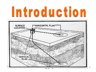
  • 5. MULTIPLE WELLS FROM SINGLE LOCATION Optimum number of wells can be drilled from a single platform or artificial island. This greatly simplifies gathering systems and production techniques . 5
  • 6. 6
  • 7. INACCESSIBLE LOCATIONS If reservoir located under river beds, mountains, cities etc, this technique of directional drilling is used . 7
  • 8. 8
  • 9. DRILLING TO AVOID GEOLOGICAL PROBLEMS A. FAULT DRILLING: This eliminates the hazard of drilling a vertical well through steeply inclined fault plane which could slip and shear the casing. 9
  • 10. 10
  • 11. B. SALT DOME DRILLING To reach the producing formation which often lie underneath the over hanging cap of the dome, the well is first drilled at one side of the dome and is then deviated to producing zone to avoid drilling problems such as large washouts, lost circulation and corrosion . 11
  • 13. SIDE TRACKING & STRAIGHTENING It is used as remedial operation either to side track obstruction by deviating the well bore away from obstruction by deviating the well bore back to vertical by straightening out crooked holes. 13
  • 14. 14
  • 15. RELIEF WELL DRILLING The technique is applied to the drilling of relief wells so that mud may be pumped into the reservoir of the uncontrolled well. 15
  • 16. 16
  • 17. ERD WELL Advantages: 1.Increased horizontal displacement from central platform. 2. Increased penetration length of reservoir. 3. Require less number of wells to develop a field. 4. Require less number of platforms to develop a field in offshore. 17
  • 19. 19
  • 20. 20
  • 21. HORIZONTAL WELL Advantages: 1.Increasing the drainage area. 2.Prevention of gas coning or water coning problems. 3.Increased penetration of the producing formation. 4.Increasing the efficiency of enhanced oil recovery ( EOR ). 5.Improving productivity in fractured reservoirs by intersecting a numbers of vertical fractures. 21
  • 24. 24
  • 25. Mutilateral. Drilling Multilateral well has been defined as a well that has more than one horizontal or near horizontal laterals drilled from single site and connected back to a single well bore. Applications . Greater reservoir exposure. · Drain more than one reservoir. · Exploit irregular reservoirs efficiently. · Speed up reservoir drainage. · 25
  • 26. Mutilateral. Drilling · Reduction in drilling cost per unit length of the well bore contacting, the reservoir rock. · Ability to obtain a given length of horizontal well bore in reservoir where drag would perhaps limit the length of single horizontal well bore. · Reduction in number of slots and thus the number of production platforms. 26
  • 28. NON PETROLEUM APPLICATIONS A. MINING INDUSTRY - Directional wells are used to produce methane gas that is contained in coal seams. - Methane presents a safety hazard and must be drained off before mining operations can begin. -In deep coal seams that are beyond the reach of conventional mining techniques, directional wells can be drilled for in situ gasification projects. 28
  • 29. NON PETROLEUM APPLICATIONS A. MINING INDUSTRY 29
  • 30. B. CONSTRUCTION INDUSTRY • A small diameter pilot hole is drilled in a smooth arc beneath the river until it immerges on the other side. This acts as a guide for the large diameter pipe forming the conduit. • The hole is drilled through soft sediments about 40’ below the river bed. This techniques has been used to cross rivers up to 200’ wide. 30
  • 32. C.GEO THERMAL ENGINEERING High geothermal gradient found in some rocks( e.g. granite) can be harnessed to provide energy. Extracting the heat from this rocks requires the drilling of injection and production wells. 32
  • 34. 34
  • 35. 35
  • 36. 36
  • 37. 37
  • 42. A radius of 100ft is commonly used as target zone depending on particular requirements e.g a relief well requires much smaller target in order to be effective. Smaller the target, greater number of correction runs. So longer drilling time , high drilling costs. So the target zone should be as large as the geologist/reservoir engineer can allow. DD’s job is then to place the wellbore within the target zone at minimum cost 42
  • 43. 43
  • 44. TYPES OF WELL PROFILES a. L- TYPE b. S- TYPE c. J- TYPE 44
  • 45. TYPE I (BUILD AND HOLD OR ‘L’ TYPE) • This is the most common and simplest profile for a directional well. • The well is drilled down vertically to KOP, where the well is deviated to required inclination and further maintained to target. • Shallow KOP selected to reduce inclination. • This profile can be applied where large displacements are required at relatively shallow target depths. • Under normal condition inclination should be 15 to 55°. 45
  • 46. 46
  • 47. TYPE II (BUILD HOLD AND DROP OR ‘S’ TYPE) •This profile is similar to type-I up to tangential section. Here the profile enters a drop of section where inclination is reduced and in some cases becomes vertical as it reaches the target. •More torque and drag can be expected due to the additional bend. •Used where target is deep but horizontal displacement is relatively small. •It has also application when completing a well that intersect multiple producing zones. •Drilling of relief well where it is necessary to run parallel to wild well •Lease or target limitations. 47
  • 48. 48
  • 49. TYPE III (DEEP KICK OFF AND BUILD ‘J’ TYPE) • Initial deflection is started well below the surface and angle is built up to bottom. • It is used in particular situations like salt dome drilling, fault drilling and side- tracking or repositioning of target. • Disadvantages: • Formation may be harder & less responsive to deflection. • More tripping time to change BHA while deflecting. • BUR is more difficult to control. 49
  • 50. 50
  • 51. 51
  • 52. 52
  • 53. HORIZONTAL WELL PROFILES • HORIZONTAL WELLS ARE CATEGORIZED BY THE RADIUS OF CURVATURE ADOPTED TO MAKE THE WELL HORIZONTAL. THEY ARE ALSO CLASSIFIED BY BUILD UP RATES WHICH IS INVERSELY PROPORTIONAL TO THE RADIUS OF CURVATURE: – LONG RADIUS – MEDIUM RADIUS – SHORT RADIUS – ULTRA SHORT RADIUS 53
  • 55. BUILDUP SECTION BETWEEN 1°- 6°/100’ OR RADIUS LENGTH BETWEEN 1000’-5000’ • ADVANTAGES:- – EASIER AS CONVENTIONAL DOWNHOLE HARDWARE IS USED – PDM MAY NOT BE REQUIRED – LOWER DOG - LEG SEVERITY GIVES LESS TORQUE AND DRAG – LONGER LATERAL SECTIONS(3500’ TO 5000’) (1000M TO 1500M) – EXTENDED REACH FROM SURFACE LOCATIONS – ACCOMMODATES FULL LOGGING ALL COMPLETION METHODS STIMULATION WORKOVER AND GASLIFT EQUIPMENT. • DISADVANTAGES:- – LONG RADIUS NECESSITATES BIGGER RIG, TOP DRIVE, LARGER PUMPS AND GREATER MUD MANAGEMENT CAPABILITIES – LONGER OPEN HOLE SECTIONS INCREASE RISK OF PIPE STICKING ,KICKS AND BOREHOLE DAMAGE – LESS PRECISE CONTROL OVER T.V.D – LITTLE USE IN SMALL LEASES BECAUSE OF LONG DISPLACEMENTS. Long Radius 55
  • 57. • BUILDUP SECTION BETWEEN 8°-20°/100’ OR RADIUS LENGTH BETWEEN 716’ TO 286’(218M TO 87M) – ADVANTAGES:- • SUPERIOR IN PRECISION COMPARED TO LONG RADIUS • ACCOMMODATION OF NORMAL/SMALL SIZE M.W.D TOOLS • ABLE TO DRILL LONG HORIZONTAL SECTION UPTO 5000’ – DISADVANTAGES:- • TORQUE AND DRAG HIGHER THAN LONG RADIUS • LIMITATION IN COMPLETION AND WORKOVER OPERATIONS Medium Radius 57
  • 59. • Buildup section between 1°-3.5°/1’ and radius length between 57’ to 16’ – Advantages:- • Precise vertical placement of horizontal drain • KOP below fluid contacts results less risk of poor isolation – Disadvantages:- • Requires customized drilling equipment • No control over bore hole azimuth (within 20°) • Limited to open hole completion • No coring and logging services Short Radius 59
  • 61. 61
  • 63. DROPPING ROTARY ASSEMBLY • Angle dropping principle is based on pendulum principle • Placing a stabilizer above the point of tangency causes a reverse action and the assembly becomes an angle dropping assembly. • The section of drill collars below the stabilizer bends and sags downwards due to pull of gravity, somewhat like the action of a pendulum. so this assembly is often called as pendulum assembly.
  • 64. The stabilizer is normally placed 30’, 60’ or 90’ above the bit. As the distance increases, more bend occurs and more drill collar weight forces the bit to the lower side of the hole resulting in increase of angle dropping rate. Tentative guideline 30’: 0.25-.75°/100’ 60’: 0.5-1.25°/100’ 90’: 0.5-2.5°/100’ Variables for dropping rate • Stiffer the drill collar, less the bending rate. • More the drift angle in the well, greater the dropping rate • Higher the WOB, lesser the angle drop rate • All the variables equal (drift angle, WOB etc., increase in rotary speed will result in increase in angle drop. The exact position of stabilizer depends on drill collar size and weight, hole diameter, inclination and WOB The is adjusted with subs and pony drill collars to increase or decrease the rate of drop
  • 65. HOLDING ASSEMBLY: • Packed hole assemblies are used when it is necessary to keep angle and direction change to a minimum • In directional wells, packed hole assemblies are used after the maximum drift angle is reached and it is desired to maintain the angle. • The stiff rigid assembly fits closely in the hole and is held in place by multiple stabilizers. • The stabilizers are normally placed at 0-10’-40’ or 0-10’-40-70’ above the bit. • The rigidity and stiffness force the bha to remain in the same relative position. • Its efficiency increases by increasing stiffness and rigidity
  • 66. Given set of conditions determining hole size, d/collar size, inclination, WOB, to lesser degree RPM , these two stabilizer systems will have greater build tendency from 4 to 1.
  • 67. Three stabilizer packed hole assemblies are designed to hold the bit on course. These assemblies may build or drop gradually due to local conditions and may be fine tuned by the use of under gauge stabilizers.