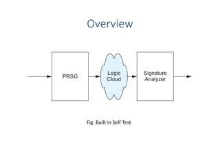
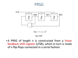
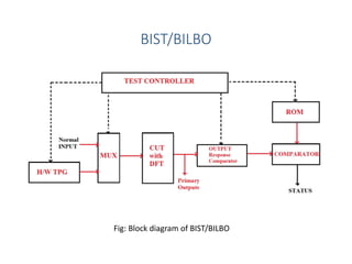
Built-in self-test (BIST) is a technique that uses on-chip circuitry to test other parts of the chip. It involves a pseudo-random sequence generator (PRSG) to produce input signals and a signature analyzer to observe outputs. A PRSG is typically a linear feedback shift register (LFSR) that cycles through a pseudo-random sequence. A signature analyzer receives outputs and XORs them to produce a syndrome signature that is compared to a correct signature to determine if the circuit passed the test. BIST provides advantages like lower cost and better fault coverage compared to external testing. However, it requires additional silicon area and the on-chip test circuitry could also fail.

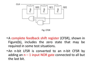
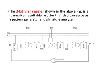
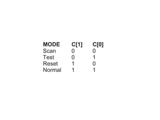
![•C[1:0] specifies the mode of operation.
• In the reset mode (10), all the flip-flops are
synchronously initialized to 0.
•In normal mode (11), the flip-flops behave normally
with their D input and Q output.
• In scan mode (00), the flip-flops are configured as a
3-bit shift register between SI and SO.
•Note that there is an inversion between each stage.
•In test mode (01), the register behaves as a pseudo-
random sequence generator or signature analyzer.](https://image.slidesharecdn.com/bist-230524081535-7d2e6eb6/85/Introduction-to-Built-In-Self-Test-BIST-pdf-12-320.jpg)