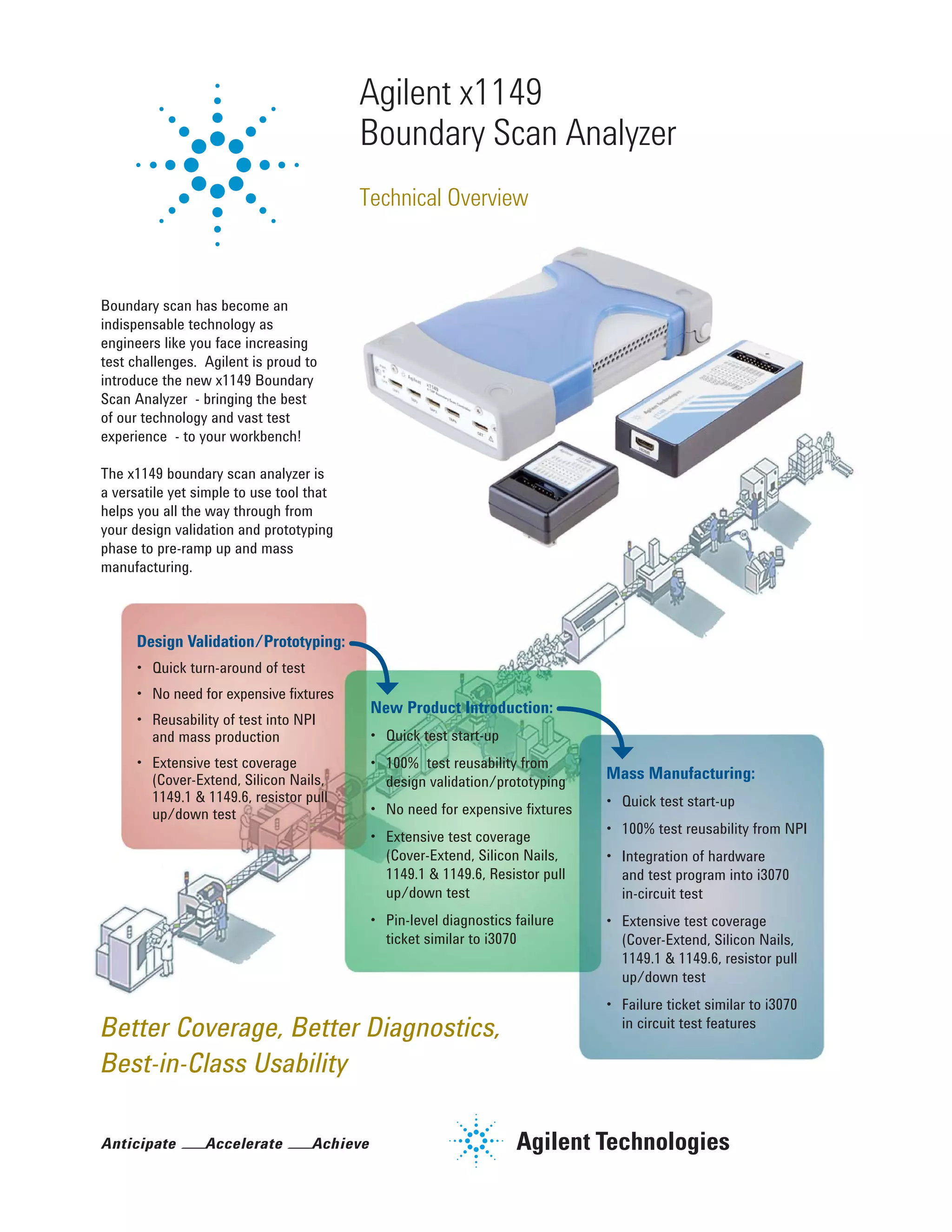
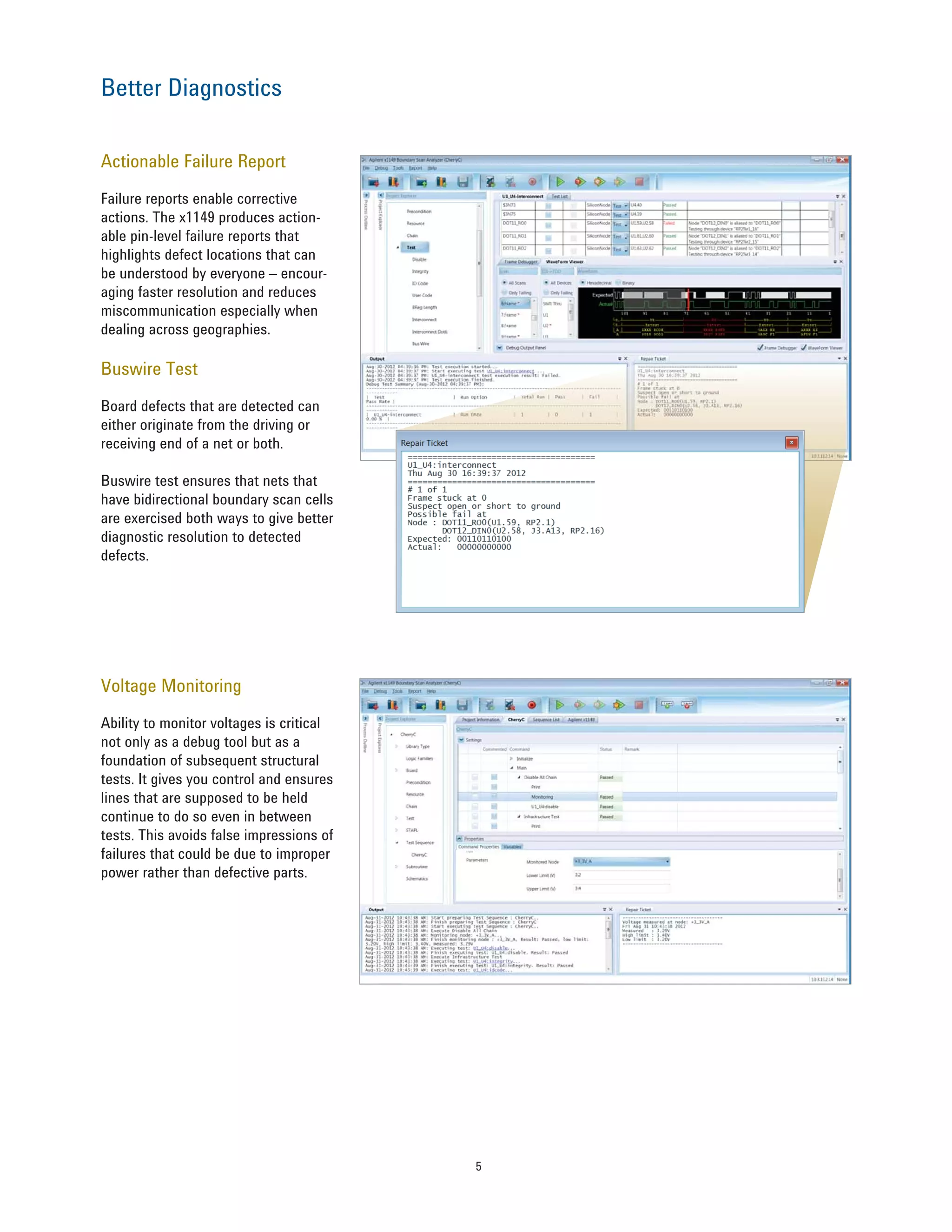
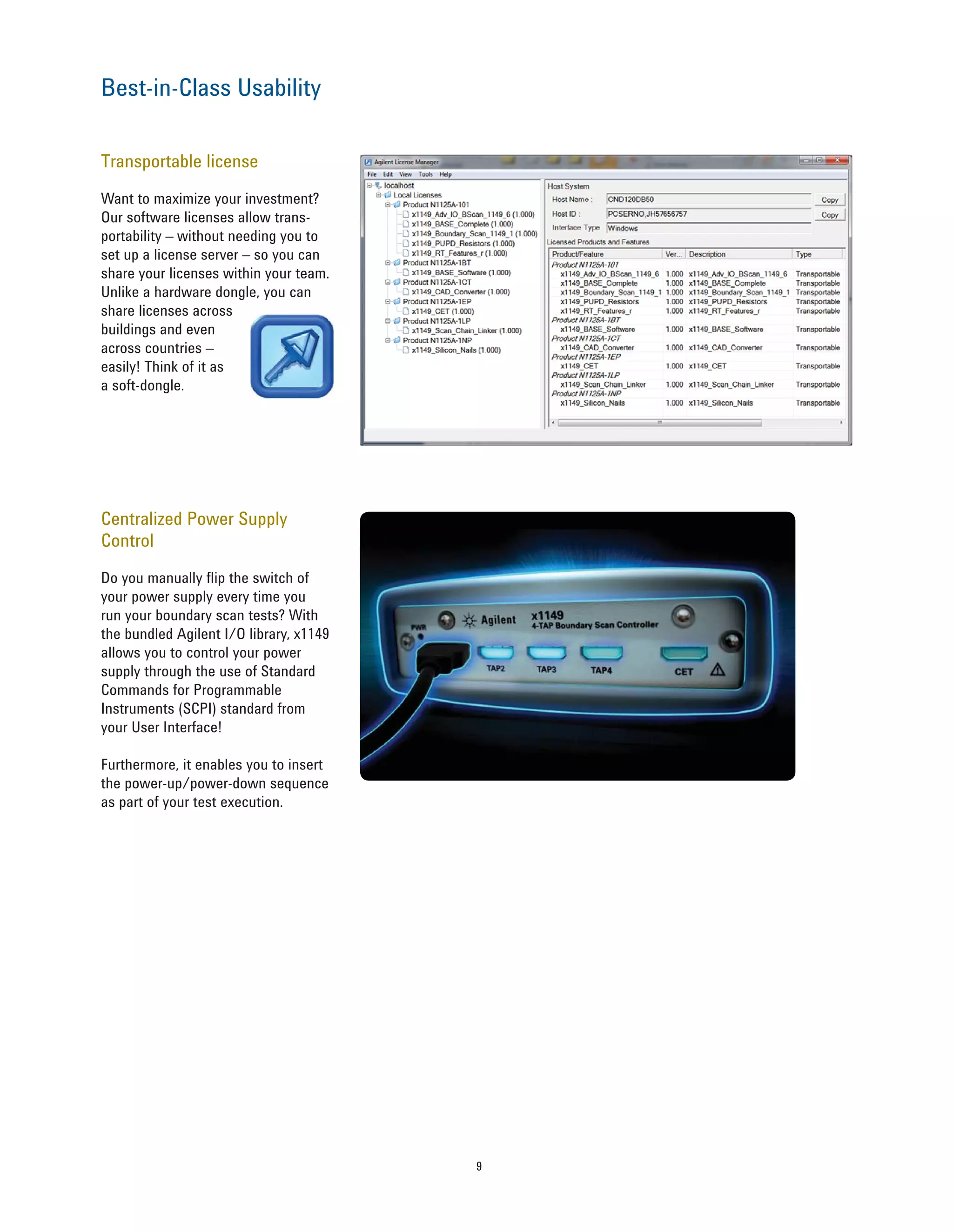
Boundary scan has become an indispensable technology as engineers like you face increasing test challenges. Agilent is proud to introduce the new x1149 Boundary Scan Analyzer - bringing the best of our technology and vast test experience - to your workbench!
Boundary Scan Basics - x1149 de KeysightInterlatin
Descubre los principios básicos sobre qué es Boundary Scan en la prueba electrónica, por qué es necesaria y cómo puedes tenerla como parte de tus sistemas de prueba gracias al x1149 de Keysight Technologies.
Boundary scan for support engineers and techniciansInterlatin
Boundary scan in one of the most important electronic tests in the actual automotive, medical and consumer electronic manufacturing. Keysight Technologies electronic test systems have the capability to do this test - systems such as i3070 and the x1149 which provides boundary scan in a box. This training focuses on this test used by support engineers and technicians.
Muchos ingenieros de prueba electrónica están muy acostumbrados a trabajar con la interfaz de UNIX y se niegan a cambiar a Windows, basados en rumores y/o falta de información. En este entrenamiento, encontrarán lo fácil que es hacer la migración entre Unix y Windows y todas las ventajas que tiene utilizar Windows en los equipos ICT de Keysight Technologies
Cuando el espacio es una variable importante en el proceso de manufactura electrónica el Mini-ICT te permite funcionalidades similares a las de un Keysight i1000 pero en un tamaño compacto.
Básicos de Functional Test Systems - Testing Days TijuanaInterlatin
The document discusses Keysight's TS-5XXX functional test platform and its applications. It provides an agenda for a training covering TS-5400 test platforms, selecting the right solution based on product type, and using load and pin matrix cards for applications like sensor emulation and instrument multiplexing. Examples are given of using load cards to simulate inputs and outputs and for testing a simple body control module. Keysight's test platform advantages are listed as formal training, mature and sustained platform, third party hardware integration support, and standard test sequencer software.
This document summarizes the Medalist i3070 08.30p software release from Agilent Technologies. It includes an agenda that covers the software milestone, what's new in version 08.30p, and how to get the updated software. An appendix lists over 200 change requests that have been addressed in this release.
Keysight i3070 (antes HP3070) Board Test InterfaceInterlatin
This document discusses new features of Keysight's Board Test Insight (BTI) software for the Medalist i3070 in-circuit test system. Some key features discussed include an updated testplan editor with syntax highlighting, smart docking panels, search functions and debugging tools. The software is designed to be more intuitive for younger engineers while still supporting existing BT-Basic testplans. New features also aim to improve throughput, quality control and debugging capabilities.
i3070 Series 5i E9988E, 2 Module In-line ICTInterlatin
This document provides an overview of the i3070 Series 5i 2 Module In-line ICT system. It describes the key components of the system including the controller pod, in-feed stage, press unit, test stage, test engine, and software. It also provides details on the fixture specifications, ID block signals, and questions and answers section. The document is intended as a presentation for customers on the new inline ICT system from Agilent.
Mexico 3070 user group meeting 2012 test coverage johnInterlatin
This document discusses improving test coverage using the Agilent 3070 test system. It provides an overview of boundary scan testing and its benefits for testing interconnects without understanding device functionality. It also discusses various tools and techniques the 3070 uses to increase coverage, such as coverage extend combining boundary scan and VTEP testing. The document outlines definitions of different levels of test coverage and common defects tested at each level. It provides a brief history of boundary scan standards and some proposed new extensions. Overall, the document aims to help test engineers understand how to maximize coverage using the capabilities of the 3070.
In considering the techniques that may be used for digital circuit testing, two distinct philosophies may be found, First is Functional Testing, which undertake a series of functional tests and check for the correct (fault free) 0 or 1 output response. It does not consider how the circuit is designed, but only that it gives the correct output during test and second one is Fault Modelling in whichto consider the possible Faults that may occur within the circuit, and then to apply a series of tests which are specifically formulated to check whether each of these faults is present or not.The faults which are likely to occur on the wafer during the manufacture of the ICs, and compute the result on the circuit output(s) with or without each fault present. Each of the final series of tests is then designed to show that a particular fault is present or not.
El siguiente entrenamiento es sobre el programa para la creación de aplicaciones de prueba de Keysight Technologies TestExec y las ventajas que ofrece la versión 8.1 del mismo - threaded sequence
Mexico 3070 user group meeting 2012 automationInterlatin
The document summarizes Agilent's automation capabilities and partnerships. It discusses Agilent's early development of in-circuit test automation in the 1990s and continued partnerships with handlers. Recent projects have focused on customizing smaller footprint test systems for production. Potential automation considerations and solutions are outlined, including integrating Agilent test systems with multi-function test handlers for in-line production.
quick design and routing support services to ATE designers involved in designing of loadboards,BiBs,probecards,handler and probe interface boards , motherboards and characterization boards. MLO/MLC substrate designing.
Design, Implementation and Security Analysis of Hardware Trojan Threats in FPGAVivek Venugopalan
This document discusses hardware Trojan threats in FPGAs. It proposes a novel metric called the Hardware Trojan Threat Detectability Metric (HDM) that uses weighted physical parameters to detect Trojans. Several Trojans were designed and implemented in an FPGA testbed to compromise systems. HDM increased detection rates to 86% compared to 57% using single parameters. The document analyzes potential attack surfaces in FPGAs and discusses optimization of Trojans to avoid detection.
Hardware Trojan detection using Clock sweeping methodAshish Maurya
The document summarizes a presentation on detecting hardware Trojans using clock sweeping. It introduces the clock sweeping technique, which involves applying test patterns at different clock frequencies to obtain path delay information without additional hardware. Signatures are generated from the path delay data and compared to identify potential Trojans. The technique aims to detect Trojans through their impact on circuit delays, especially shorter paths. It is shown to be effective for critical and non-critical paths, and can detect Trojans without full activation. However, process variations and measurement noise still pose challenges.
This is a seminar on hardware trojan that i have given during my M.tech. It follows the latest classification of hardware trojans used in research community. 3 latest hardware trojan detection technique and 2 insertion techniques are presented in slides.
The document discusses hardware Trojan detection techniques. It describes the objective of detecting Trojans in circuits by analyzing power and delay. It then discusses different Trojan detection techniques like power measurement, path delay measurement, and physical design based testing. It also describes different types of hardware Trojans and provides implementation results of detecting Trojans in circuits like an 8:1 MUX and full adder using LBIST. LBIST was also implemented in an AES core to detect Trojans, achieving high test coverage while detecting minimal changes in area and power between Trojan-free and Trojan-inserted circuits.
Tools for Practical Attacks on Analog-to-Digital ConversionAlexander Bolshev
This document discusses practical attacks on analog-to-digital converters (ADCs). It begins with an anecdote about compromising a programmable logic controller (PLC) and bypassing monitoring systems. It then covers different types of ADCs and their vulnerabilities. Examples are provided of proof-of-concept attacks injecting arbitrary waveform signals and altering the digital representation of analog signals. Various hardware is demonstrated for evaluating ADCs, including signal generators, function generators, and data acquisition systems. Mitigation techniques are proposed, such as implementing appropriate anti-aliasing filters and randomizing sampling frequencies.
Learn about TAP Checker, a software tool for BSDL verification and automated validation of chip-level JTAG / boundary-scan implementations;
support for multi-chip modules; IEEE 1149.1 and IEEE 1149.6 compliant; VHDL, VERILOG, and STIL output;
This document discusses sales opportunities in protective relaying by upgrading from electromechanical relays to microprocessor relays. Some key opportunities include:
1) Upgrading provides customers benefits like less testing requirements, improved compliance, usability, and troubleshooting capabilities.
2) Service companies benefit from markup on the relays, engineering, commissioning, and testing labor required for upgrades.
3) Upgrading to arc flash relays provides additional customer safety benefits and opportunities for service companies to take on switching contracts and studies.
4) Regular firmware upgrades provide benefits to customers and opportunities for service work.
Hardware trojan detection technique using side channel analysis for hardware ...Ashish Maurya
The document presents two techniques for detecting hardware Trojans: detection using power analysis and detection using active current sensing circuits. For power analysis, a ring oscillator network is used to detect Trojans by measuring changes in oscillation frequency from power supply noise. NAND gate-based ring oscillators are more sensitive than NOT gate-based ones. For current sensing, circuits measure switching activity and path delays to detect Trojans even if they do not impact delays or power. Both techniques aim to detect rarely activated Trojans through side-channel analysis of power signatures.
Hardware Trojans, a relatively unheard threat viz-a-viz the typical software based malwares and virus attacks ,that keep befalling across is being realized gradually by the IT security domain including the users, the IT Security guys and the corporate sector who all of a sudden recognize the immense threat they might already be living in with. A distinctive dormant Hardware Trojan threat can be so flagitious that the victim doesn’t even know if he is effectuated when he might already be. Hardware Trojans are evolving threats that can shake the roots of any set and constituted government or corporate giant for that matter. Unlike Software virus/malware threats, Hardware Trojans are persistent in nature ie once infected in an IC, the threat remains and cannot be removed even once detected. The presentation i plan to run will bring out the over view of these threats including classifications, mechanisms they work on,few case studies and the current set of countermeasures being researched upon.
This document describes hardware trojans and techniques for detecting them. It discusses how modern design practices have increased security risks by outsourcing fabrication and using third-party IP. Hardware trojans maliciously tamper with designs by adding a small number of gates. Detection methods discussed include logic testing, side-channel analysis, and design-for-trust techniques. A statistical approach called MERO generates test patterns to activate rare events in the design in order to detect trojans added by combining rare trigger conditions. The focus is on detecting trojans with eight or fewer activation nodes.
The document discusses using a JTAG interface to reprogram receivers when the firmware is corrupted or a firmware update fails. It explains that receivers use a bootloader program to run the firmware from flash memory. If the bootloader is still intact but the firmware is corrupted, the receiver can still be reprogrammed via JTAG. If the bootloader is also corrupted, reprogramming may still be possible if the manufacturer provides JTAG software and the pinout layout. The document provides steps for using jKeys software to reprogram an STi-based receiver via JTAG, including downloading the flash memory contents as a backup, deleting the flash, and programming new firmware.
This document provides an introduction to the Keysight x1149 boundary scan analyzer. It describes the system components which include a main controller connected to up to four TAP/IO boxes and a diagnostic clip. The document outlines the system's applications in boundary scan testing, cover extend technology, and scan path linking. It also summarizes the graphical user interface, test development workflow, and use of the system throughout a product's life cycle from design to production.
The cable harness tester has an important role in bringing in the quality and reliability of electrical cable assemblies that are used in many industries, such as aerospace, automotive, defence, and manufacturing. This is one of the most important functions of cable harness assembly as it helps in finding defects, ensuring the connectivity is right, and testing the on-field performance of the harnesses.
Takaya Flying Test is one of the most durable and provides high-accuracy, high-speed, and good-quality long lasting mechanics. Flying Probe machines, like those offered by Takaya, can probe the ends of component pads and uncovered vias to get access to the electrical networks.
The document summarizes testing equipment from Shimadzu, including their new AG-X Precision Universal Tester series. The AG-X series focuses on reliability, easy operation, and convenient support functions. It delivers high-precision measurement performance through patented technologies and innovations. The user-friendly interface and software allow intuitive operation and efficient workflow. A variety of accessories are also available for different testing applications.
High Cost of a Low-Cost Cable Certification TesterFluke Networks
Things to consider while selecting a new certification tester for network cabling. Good certification testers also typically support performance standards for premises fiber optic cabling, and have diagnostic capabilities for both copper and fiber network cabling.
The S2000nano is an intelligent low power RTU/logger that uses WITS and DNP3 protocols (1). It has inputs and outputs that make it suitable for a wide range of applications and offers powerful processing at a competitive price (2). It can be configured using programming tools and includes features like data logging, alarms, and security (3).
RNS International is a test equipment supplier and manufacturer that provides solutions for in-circuit, functional, and special test applications. They offer test fixtures, probes, and programming solutions for various test systems. RNS has over 25 years of experience developing test fixtures and was an early innovator in technologies like pneumatic test fixtures, split top plates, and guided probe technology. Their capabilities include fixtures for ICT, FCT, and other test applications.
Extended QA testing to enhance productivity of a leading networking solution ...Veryx Technologies
This case study showcase show Veryx Technologies enabled a global industrial ethernet solution provider to meet their targets by providing extended QA testing
Smart line level transmitter sales presentationPavel Buček
This document provides an overview of Honeywell's SmartLine level transmitters and their benefits over competitors. Key points include:
- SmartLine uses advanced guided wave radar technology and a correlation algorithm to more reliably measure level compared to competitors that use simple peak detection.
- A cloud-based application and validation tool allows for online engineering collaboration to expedite transmitter configuration and reduce commissioning time.
- SmartLine offers benefits like universal transmitter wiring, modular design, advanced displays, and Experion system integration that reduce costs and improve usability.
FAST is a test system developed by Benetel that automates wireless product compliance testing to save time and costs. It tests 3G devices against 3GPP specifications for transmitter and receiver characteristics. The FAST system controls test instruments using customized software and a test set with integrated filters. It provides automated testing over various parameters, stores results in a database, and generates test reports. Key benefits include reduced verification times, improved quality through extensive testing, and freeing up engineers for more productive work.
The MaxTester 730C (MAX-730C) is designed for testing through FTTH/PON splitters for end-to-end characterization. This handheld OTDR is ideal for FTTH/PON testing, live fiber troubleshooting and metro range testing. SPI Engineers is the Authorized Distributor of EXFO in India and offers EXFO make Network tools and services at competitive prices across the country. If you want to buy MaxTester 730C - PON/metro OTDR, so kindly contact for more details- https://www.spiengineers.com/portfolio/maxtester-730c-pon-metro-otdr/
The document discusses robustness testing of systems in critical infrastructure industries using the Achilles Test Platform. The platform allows manufacturers to thoroughly test devices for cyber vulnerabilities before releasing products to market. This helps ensure devices are secure and reliable, avoids costly issues in the field, speeds time to market, and prepares devices for industry certification standards.
Qualifying a high performance memory subsysten for Functional SafetyPankaj Singh
Addressing the Challenges of Safety verification for LPDDR4.
✓Avoid traditional approach of starting functional safety after functional verification : Iterative and expensive development phase
1. Functional Safety Need to be Architected and not added later.
2. Safety Analysis must start prior to implementation. ‘Design for safety/verification’
3. Reuse & Synergize : Nominal and Functional Safety Verification.
✓Fault optimization with formal and other techniques is necessary to overcome challenges with scaling simulation and analysis.
✓Integrated push button fault simulation flow is need of hour and saves verification engineers time.
✓Analog defect modelling and coverage can be performed based on IEEE P2427.
Carrier Grade Linux (CGL) is an open-source Linux distribution designed for telecommunications carriers, providing 99.999% uptime. Effective monitoring, live patching, scalability, quality of service tools, and failure analysis are crucial for maintaining CGL after deployment. These features help detect issues, deploy security patches, incorporate new technologies, and minimize downtime from hardware failures.
The document describes how to configure and run a Scanner Only test on a QualiPoc phone to perform radio frequency scans for GSM and WCDMA networks. Key steps include selecting the scan technology (GSM or WCDMA), bands, and channel ranges. Performance can vary from 1-20 seconds depending on the configuration and device. Scan results are monitored through log files and bar charts showing signal levels and channels.
6TL-Engineering has developped a true flexible, modular test system platform concept to help engineering groups developping a reliable, flexible and efficient test system. This presentation shows the concept. used
STS Characterization to Production TestHank Lydick
The document discusses bridging the gap between RF front-end module characterization and production testing. It describes how NI's semiconductor test system (STS) uses a common PXI hardware and software platform to allow characterization and production teams to use the same instrumentation and share test data, reducing time to market. The STS integrates RF and non-RF instruments into an enclosed test head and supports various wireless standards and RF measurements.
Electrical & functional testing challenges in your company.
BOX ICT. B BOX X1149: Boundary Scan Solution. VIPER: How to take advantage of modular test systems.
This document discusses hardware design verification and testing techniques. It covers emulation architectures like FPGA-based and processor-based systems. It also discusses formal property verification methods, software formal verification, design for test objectives, chip-level DFT techniques, automatic test pattern generation, and testing techniques for analog/mixed-signal circuits like ADCs, PLLs and oscillators.
In-line fixture design and release to production Interlatin
Many test technicians and Engineers have a day-to-day battle with their test fixtures. Interlatin application and support Engineers have created this simple and concise guide to help test engineers with fixture design and management in in-line Keysight i3070 products
Análisis de respuesta en frecuencia en osciloscopiosInterlatin
Análisis de respuesta en frecuencia, diagramas de bode, decodificación de protocolos automotrices, funciones de prueba en osciloscopios de bajo costo de Keysight Technologies.
El documento describe tres etapas de la transformación en ingeniería digital: 1) Entender, mediante el uso de datos del mundo real y tecnologías como AR/VR para mejorar el diseño; 2) Avanzar, incorporando IoT para conectividad e innovación; y 3) Progresar, utilizando gemelos digitales y análisis predictivo de datos para mejorar continuamente los productos. La transformación digital permite mayor innovación, colaboración y resultados comerciales.
Inter latin ptc i-iot - viaje de transformación de la manufacturaInterlatin
La manufactura está cambiando y el Internet de las Cosas Industrial es uno de los motores de este cambio. En las siguientes diapositivas descubre las aplicaciones del Internet de las Cosas en la manufactura y su impacto en los procesos y eficiencia de la misma.
Elige la fuente de alimentación adecuada para tus aplicacionesInterlatin
El documento habla sobre las diferentes fuentes de alimentación disponibles para sistemas electrónicos. Explica que existen dos tipos principales de fuentes de alimentación de corriente continua (DC): básicas y de alto rendimiento. También menciona que hay fuentes de alimentación de corriente alterna (AC). Además, detalla algunas familias y características específicas de fuentes de alimentación DC y AC de la marca Keysight y concluye resaltando la importancia de elegir la fuente adecuada según las necesidades
Sistemas de adquisición de datos en las Fábricas Inteligentes de la Industria...Interlatin
El documento habla sobre los módulos de adquisición de datos (DAQ) de Advantech y sus aplicaciones en la era de Internet de las Cosas. Advantech es una empresa líder en sistemas integrados de hardware, software y servicios. Ofrece varias familias de módulos DAQ como ADAM, WISE-4000 y series ADAM-2000, 4000, 6000, 6100 y 6200 para aplicaciones industriales y de IoT. Estos módulos permiten la adquisición, monitoreo y control remoto de datos.
Introducción a las Redes automotrices - CAN/LINInterlatin
Este documento trata sobre las redes automotrices CAN, CANFD y LIN. Explica que la electrónica juega un papel cada vez más importante en la industria automotriz, con un aumento dramático en la cantidad de código de software en los vehículos. También describe los conceptos de multiplexado y las clases de multiplexado utilizadas en los automóviles. Luego, proporciona detalles sobre CAN y LIN, incluida su historia, elementos, funcionamiento y características. El documento concluye invitando a un curso sobre re
Pruebas de Campo para la industria de las Telecomunicaciones - Caracterizació...Interlatin
Ningún producto, servicio o mejora significativa en redes de telecomunicación puede decirse completo si no cuenta con un sistema de instrumentación para pruebas que lo respalde. Sin embargo, no fue hasta la primera década del siglo XXI cuando la instrumentación se volvió una ventaja estratégica para los operadores de redes de telecomunicaciones. En nuestro webinar, se dieron a conocer varias de las mediciones necesarias en campo y la manera óptima de realizarlas.
The document provides an agenda and information for an automotive seminar in Mexico that will take place from May 18th to May 22nd and June 1st to June 5th. The agenda includes topics on electrical and functional testing challenges as well as how to take advantage of modular test systems. The document then discusses PXI modular instrumentation and compares PXI and VXI systems. It provides examples of applications of modular instrumentation for automotive testing including immobilizers and simple body control modules. Finally, the document outlines the value propositions of Keysight's modular test solutions for automotive applications.
This document provides an overview of CAN protocol and PXI CAN modules from Interlatin. It first defines CAN protocol, describing its origins, applications, features, and frame types. It then introduces Interlatin's PXI automotive series and CAN modules, including the I0910X and I0913X models. Key features of the modules are listed, such as bus error detection, isolation, and software drivers. Finally, it invites questions from the audience.
The document outlines an agenda for a meeting that will discuss various topics including SPIN methodology, case studies, manager follow-ups, CANIETI presentations, and resource strategy proposals. It also discusses establishing a technical and management track for sharing experiences and challenges, integrating knowledge and experience across companies, and collaborating while also competing. The meeting aims to explore resource talent development strategies and what industries are willing to offer to develop the cluster.
Interpretación y utilidad de datos estadísticos.Interlatin
Histogramas
Capabilidad del Proceso
Relación entre CP y CPK
Relación entre Capabilidad y nivel Sigma
Planes de Muestreo
Análisis del Sistema de Medición
(1) El documento presenta las mejores prácticas para el uso de equipos de prueba, incluyendo el autoajuste, copias de seguridad, y el uso del administrador de software Keysight. (2) El autoajuste permite al sistema encontrar las especificaciones de fábrica para mediciones de amplitud y tiempo. (3) Hacer copias de seguridad periódicas protege contra fallas de hardware o software y ahorra tiempo al regresar el equipo a producción.
Introduccion a la Interferencia Electromagnetica y Compatibilidad Electromagn...Interlatin
El electromagnetismo es una rama de la física que estudia y unifica los fenómenos eléctricos y magnéticos en una sola teoría, cuyos fundamentos fueron sentados por Michael Faraday y formulados por primera vez de modo completo por James Clerk Maxwell. La interferencia electromagnética es la emisión de energía electromagnética que degrada o perjudica la calidad de una señal o el funcionamiento de un sistema.
La compatibilidad electromagnética es la habilidad de un sistema de no causar interferencias electromagnéticas a otros equipos, pero al mismo tiempo ha de ser insensible a las emisiones que pueden causar otros sistemas.
El mal funcionamiento de un dispositivo puede tener serias consecuencias como: fallas en sistemas de control de vuelo en aviones, problemas en vehículos de motor, atmósferas flamables, dispositivos médicos defectuosos, entre otros. Es por esto que las pruebas de EMI y EMC en un producto, tanto en la fase de diseño como en la etapa de prueba, se han vuelto una actividad fundamental en el mundo de la creación de tecnología.
En este webinar aprenda sobre todas las posibles fuentes de interferencia electromagnética, sus consecuencias en el funcionamiento de equipos eléctricos y electrónicos y las diferentes herramientas que existen en la actualidad para detectar y corregir las fallas provocadas. Observe en vivo, una demostración de algunos de estos equipos de última tecnología mientras ayudan a nuestros ingenieros a detectar cualquier posible fuente de electromagnetismo en diferentes productos.
AGENDA:
Introducción
Interferencia Electromagnética (EMI)
Compatibilidad Electromagnética (EMC)
Susceptibilidad Electromagnética (EMS)
Soluciones actuales para la industria en EMC/EMI/EMS
EMscan
Respuestas de la trivia del mes de julio. ¡Gracias por participar!Interlatin
Aquí les enviamos las respuestas correctas de nuestra trivia para participar en el sorteo de una iPad mini. Sólo participaron las personas que respondieron correctamente. Gracias a todos por participar y por preferir InterLatin.
Este documento resume las respuestas correctas a 5 preguntas sobre el nuevo sitio web de una compañía y sus divisiones de productos. Las preguntas incluyen los nombres de marcas representadas, el significado de las siglas EPD, los productos desarrollados por EPD, el socio de negocios de la división de Test y la cantidad de cursos disponibles en el departamento de entrenamiento de Test.
This document provides an overview and instructions for creating and using .NET actions, hardware handlers, and operator user interfaces in TestExec SL. Key points include:
- .NET actions allow writing test routines in C# or VB.NET and compiling them into DLLs containing executable action routines. Instructions are provided on creating .NET action libraries and projects.
- Hardware handlers can also be written in .NET style using C# or VB.NET. The document outlines the predefined interfaces and members that must be implemented.
- The operator UI can be developed as a .NET application using the TestExec SL ActiveX control. Examples of typical and multiple device UIs are included.
Throughout the document, code
This document discusses using IVI-COM actions in TestExec SL. It introduces IVI drivers and their benefits, and explains how to set up an IVI-COM action in TestExec SL. Key points include:
- IVI drivers provide hardware interchangeability, software interoperability, and ease of use
- The system.ust file is used to configure IVI drivers
- IVI-COM actions allow accessing instruments through IVI drivers without SCPI commands
- IVI class drivers are generic across instrument models while specific drivers target a particular model
One Testhead for Both Inline and Offline
No more investment waste
Field Upgradeable
Fully Agilent
Smallest ICT In the World
850mm in length
Largest bottom side clearance
ICT with full powered testing capabilities
This manual describes how to customize various aspects of HP TestExec SL,
such as creating custom operator interfaces, writing switching handlers from
scratch, customizing datalogging, and customizing online help.
Charging and Fueling Infrastructure Grant: Round 2 by Brandt HertensteinForth
Brandt Hertenstein, Program Manager of the Electrification Coalition gave this presentation at the Forth and Electrification Coalition CFI Grant Program - Overview and Technical Assistance webinar on June 12, 2024.
Implementing ELDs or Electronic Logging Devices is slowly but surely becoming the norm in fleet management. Why? Well, integrating ELDs and associated connected vehicle solutions like fleet tracking devices lets businesses and their in-house fleet managers reap several benefits. Check out the post below to learn more.
EV Charging at MFH Properties by Whitaker JamiesonForth
Whitaker Jamieson, Senior Specialist at Forth, gave this presentation at the Forth Addressing The Challenges of Charging at Multi-Family Housing webinar on June 11, 2024.
Charging Fueling & Infrastructure (CFI) Program by Kevin MillerForth
Kevin Miller, Senior Advisor, Business Models of the Joint Office of Energy and Transportation gave this presentation at the Forth and Electrification Coalition CFI Grant Program - Overview and Technical Assistance webinar on June 12, 2024.
Charging Fueling & Infrastructure (CFI) Program Resources by Cat PleinForth
Cat Plein, Development & Communications Director of Forth, gave this presentation at the Forth and Electrification Coalition CFI Grant Program - Overview and Technical Assistance webinar on June 12, 2024.
Dahua provides a comprehensive guide on how to install their security camera systems. Learn about the different types of cameras and system components, as well as the installation process.
Welcome to ASP Cranes, your trusted partner for crane solutions in Raipur, Chhattisgarh! With years of experience and a commitment to excellence, we offer a comprehensive range of crane services tailored to meet your lifting and material handling needs.
At ASP Cranes, we understand the importance of reliable and efficient crane operations in various industries, from construction and manufacturing to logistics and infrastructure development. That's why we strive to deliver top-notch solutions that enhance productivity, safety, and cost-effectiveness for our clients.
Our services include:
Crane Rental: Whether you need a crawler crane for heavy lifting or a hydraulic crane for versatile operations, we have a diverse fleet of well-maintained cranes available for rent. Our rental options are flexible and can be customized to suit your project requirements.
Crane Sales: Looking to invest in a crane for your business? We offer a wide selection of new and used cranes from leading manufacturers, ensuring you find the perfect equipment to match your needs and budget.
Crane Maintenance and Repair: To ensure optimal performance and safety, regular maintenance and timely repairs are essential for cranes. Our team of skilled technicians provides comprehensive maintenance and repair services to keep your equipment running smoothly and minimize downtime.
Crane Operator Training: Proper training is crucial for safe and efficient crane operation. We offer specialized training programs conducted by certified instructors to equip operators with the skills and knowledge they need to handle cranes effectively.
Custom Solutions: We understand that every project is unique, which is why we offer custom crane solutions tailored to your specific requirements. Whether you need modifications, attachments, or specialized equipment, we can design and implement solutions that meet your needs.
At ASP Cranes, customer satisfaction is our top priority. We are dedicated to delivering reliable, cost-effective, and innovative crane solutions that exceed expectations. Contact us today to learn more about our services and how we can support your project in Raipur, Chhattisgarh, and beyond. Let ASP Cranes be your trusted partner for all your crane needs!
Understanding Catalytic Converter Theft:
What is a Catalytic Converter?: Learn about the function of catalytic converters in vehicles and why they are targeted by thieves.
Why are They Stolen?: Discover the valuable metals inside catalytic converters (such as platinum, palladium, and rhodium) that make them attractive to criminals.
Steps to Prevent Catalytic Converter Theft:
Parking Strategies: Tips on where and how to park your vehicle to reduce the risk of theft, such as parking in well-lit areas or secure garages.
Protective Devices: Overview of various anti-theft devices available, including catalytic converter locks, shields, and alarms.
Etching and Marking: The benefits of etching your vehicle’s VIN on the catalytic converter or using a catalytic converter marking kit to make it traceable and less appealing to thieves.
Surveillance and Monitoring: Recommendations for using security cameras and motion-sensor lights to deter thieves.
Statistics and Insights:
Theft Rates by Borough: Analysis of data to determine which borough in NYC experiences the highest rate of catalytic converter thefts.
Recent Trends: Current trends and patterns in catalytic converter thefts to help you stay aware of emerging hotspots and tactics used by thieves.
Benefits of This Presentation:
Awareness: Increase your awareness about catalytic converter theft and its impact on vehicle owners.
Practical Tips: Gain actionable insights and tips to effectively prevent catalytic converter theft.
Local Insights: Understand the specific risks in different NYC boroughs, helping you take targeted preventive measures.
This presentation aims to equip you with the knowledge and tools needed to protect your vehicle from catalytic converter theft, ensuring you are prepared and proactive in safeguarding your property.
Expanding Access to Affordable At-Home EV Charging by Vanessa WarheitForth
Vanessa Warheit, Co-Founder of EV Charging for All, gave this presentation at the Forth Addressing The Challenges of Charging at Multi-Family Housing webinar on June 11, 2024.
Expanding Access to Affordable At-Home EV Charging by Vanessa Warheit
Agilent x1149 Boundary Scan Analyzer
1. Agilent x1149
Boundary Scan Analyzer
Technical Overview
Better Coverage, Better Diagnostics,
Best-in-Class Usability
Boundary scan has become an
indispensable technology as
engineers like you face increasing
test challenges. Agilent is proud to
introduce the new x1149 Boundary
Scan Analyzer - bringing the best
of our technology and vast test
experience - to your workbench!
The x1149 boundary scan analyzer is
a versatile yet simple to use tool that
helps you all the way through from
your design validation and prototyping
phase to pre-ramp up and mass
manufacturing.
New Product Introduction:
• Quick test start-up
• 100% test reusability from
design validation/prototyping
• No need for expensive fixtures
• Extensive test coverage
(Cover-Extend, Silicon Nails,
1149.1 & 1149.6, Resistor pull
up/down test
• Pin-level diagnostics failure
ticket similar to i3070
Design Validation/Prototyping:
• Quick turn-around of test
• No need for expensive fixtures
• Reusability of test into NPI
and mass production
• Extensive test coverage
(Cover-Extend, Silicon Nails,
1149.1 & 1149.6, resistor pull
up/down test
Mass Manufacturing:
• Quick test start-up
• 100% test reusability from NPI
• Integration of hardware
and test program into i3070
in-circuit test
• Extensive test coverage
(Cover-Extend, Silicon Nails,
1149.1 & 1149.6, resistor pull
up/down test
• Failure ticket similar to i3070
in circuit test features
2. 2
Cover-Extend Technology (CET)
x1149 is the only bench top solution in the market that offers Cover-Extend
Technology (CET). CET is a patented and award-winning* innovation that com-
bines boundary scan and capacitive-coupled sensing technology. (See inset on
how it works.)
• Provides easy coverage
• Extends coverage for non-scan components
• No extra cost working with digital plug-in modules for connectors
• No hassle writing libraries
• Based upon Vectorless Test Extended Performance (VTEP), an industry-
proven technology
• Auto-debug
How does it work?
1. The VTEP sensor, which is able to capacitively pick
up electrical signals, is placed on the component to
be tested (e.g. a connector).
2. By controlling the test access port, users can control
the boundary scan device to drive out stimulus signals.
3. The stimulus signal is delivered to the connector
where the VTEP sensor is.
4. A defect (e.g. an open) in the path between the
boundary scan device and the VTEP sensor will affect
the stimulus signal that is bound for the sensor.
5. The result is captured and diagnosed by the x1149
Boundary Scan Analyzer and thus, the defect is
detected!
Non Boundary Scan Device/Component
Boundary Scan
device
Cover-Extend Technology
VTEP sensor
TDI
TCK
TMS
TD0
No access
needed
* Winner of TMW Best In Test 2009, Circuit Assembly NPI 2009, SMT Vision 2009, EMAsia Innovation 2009, SMT China Vision 2009, EDN Innovation
2008, IPC Innovative Technology Center Award 2008.
Better Coverage
Key features
• Cover-Extend Technology
(coverage on non-scan components)
• In-system programming for CPLD/FPGA
• Integrated scan-path linker
• Actionable pin-level failure reporting
• Built-in remote access via Ethernet
• 22.5 MHz test clock
• 4 dedicated TAP/IO ports
• Hardware
• 4-test access port (TAP) boundary scan controller
• Boundary scan TAP/IO ports
• Self-diagnostic clip
• 12 V power supply
• LAN cable
• USB cable
• HDMI cable with filter
• Ribbon cable 20-pin female-to-female
• CET module (accessory)
3. 3
In-System Programmer
Programming CPLDs and FPGAs has
never been easier. With a built-in
Standard Test And Programming
Language (STAPL) player, program-
ming these devices is as a simple as
executing a file.
The software accepts any of these
file formats: STAPL, SVF, JAM and
JBC which it takes and executes
using the built-in engine. You can
change the files as you go, making
the implementation of In-system
Programming simple while leveraging
upon your efforts upstream.
Integrated Scan Path Linker
With your integrated scan path linker,
you have the power to maximize
test coverage on interconnect nodes
between scan chains by linking them
into one; test coverage that you won’t
otherwise have if the chains were
treated separately. During your debug,
you may decide to keep the chains
separate and break up a linked-up
chain – the flexibility is yours!
Better Coverage
IEEE 1149.6
Cover today’s high speed digital net-
works such as AC-coupled differential
lines. Your x1149 unit already comes
with support for the IEEE 1149.6
standard.
4. 4
Shorted Capacitors
With the implementation of IEEE
1149.6 on advanced digital networks,
you have the additional coverage on
shorted coupling capacitors. The test
effectiveness depends on the ability
to properly manage the timing of
state changes in relation to the time
constant of the AC-coupled capacitor.
All this is done automatically for you
in the background.
Pull-up/Pull-down Resistors
Modern board designs are peppered
with either pull-up resistors or pull-
down ones for purposes of termina-
tion, voltage divide, logic tie, etc.
x1149 gives users coverage on these
components as a default feature
using the network of boundary scan
cells to determine their presence.
Silicon Nails
Got non-boundary-scan devices?
No problem. Silicon nails test, or
sometimes called cluster test, uses
the boundary scan cells in the scan
chain as drivers and/or receivers to
stimulate non-boundary scan devices
which may include memory devices.
Silicon nails increases your test cov-
erage as you are no longer confined
to just IEEE 1149.x compliant devices.
Better Coverage
5. 5
Actionable Failure Report
Failure reports enable corrective
actions. The x1149 produces action-
able pin-level failure reports that
highlights defect locations that can
be understood by everyone – encour-
aging faster resolution and reduces
miscommunication especially when
dealing across geographies.
Buswire Test
Board defects that are detected can
either originate from the driving or
receiving end of a net or both.
Buswire test ensures that nets that
have bidirectional boundary scan cells
are exercised both ways to give better
diagnostic resolution to detected
defects.
Better Diagnostics
Voltage Monitoring
Ability to monitor voltages is critical
not only as a debug tool but as a
foundation of subsequent structural
tests. It gives you control and ensures
lines that are supposed to be held
continue to do so even in between
tests. This avoids false impressions of
failures that could be due to improper
power rather than defective parts.
6. 6
Coverage Report
Test coverage report tells you how
effective your tests are and how
much test coverage you are getting
before you commit your board design
to volume production.
Superior Signal Quality
Signal quality is increasingly impor-
tant as logic levels trend lower. To
prevent unintended state transitions
leading to false calls, you need to
have better control of your I/Os and
have them respond to the way you
want them to.
Agilent x1149 Boundary Scan Analyzer
Competitor PC scan
Better Diagnostics
7. 7
Best-in-class User Interface
More than ever before, usability plays
a critical role in the effectiveness
of the tools we use. User interfaces
have to be intuitive and help to intel-
ligently assist you with your tasks.
x1149 presents a user interface (UI)
that is best in class.
Automatic Scan Chain Detector
One of the key tasks when working
with boundary scan is validating the
scan chain. The UI comes with the
ability to identify the potential scan
chain! This is powerful especially
for complex and long chains. The
software is able to analyze the board
topology, even taking into consider-
ation components between boundary
scan devices to present to you how
the scan chain looks like.
Get the right BSDL
Another key task is ensuring you have
the right Boundary Scan Description
Language (BSDL) files. The UI has
a built-in BSDL syntax checker and
compiler. It is able to automatically
look for BSDL files in your deposi-
tory folder without needing you to
explicitly point to it. You can even port
over BSDL files from a known good
project – just by importing that one
project name; and not the dozens of
BSDL file names. It is cleaner, easier
and saves you time.
Best-in-Class Usability
8. 8
Best-in-class User Interface
Debug Tools
You have a number of debug tools
at your disposal. There is the Auto-
Adjust that helps you automatically
tweak various parameters like the
slew rates, TCK speed, voltage
offsets for TDI/TDO, etc. to find the
optimum setting for your UUT. The
Frame Debugger lets you do a deep
dive debug if you want to analyze
frame by frame. The Cover-Extend
Test (CET) auto debug tool helps to
automatically set the thresholds while
maintaining the level of test quality
(i.e. Cpk) that you want.
Other examples include a BOM
parser, waveform viewer and other
efficiency features like ability to do
side-by-side code comparison, filter-
ing of node names to ease viewing
and selection and much more.
Language Localization
The standard English user interface
comes with a Simplified Chinese
option. With our translation matrix,
additional languages can be added.
As your operations span the globe,
having local language support eases
your daily tasks.
Best-in-Class Usability
9. 9
Transportable license
Want to maximize your investment?
Our software licenses allow trans-
portability – without needing you to
set up a license server – so you can
share your licenses within your team.
Unlike a hardware dongle, you can
share licenses across
buildings and even
across countries –
easily! Think of it as
a soft-dongle.
Best-in-Class Usability
Centralized Power Supply
Control
Do you manually flip the switch of
your power supply every time you
run your boundary scan tests? With
the bundled Agilent I/O library, x1149
allows you to control your power
supply through the use of Standard
Commands for Programmable
Instruments (SCPI) standard from
your User Interface!
Furthermore, it enables you to insert
the power-up/power-down sequence
as part of your test execution.
10. 10
Test Sequencer
Having control of your test execution
goes beyond just rearranging the
order of tests that you want to run.
Today, engineers need the ability to
insert decision-making branches and
subroutines in addition to the usual
prompts and wait times. The x1149
test sequence gives engineers more
power over how they want the test
execution to progress.
Remote Access to Controller
Work from your desk while your
x1149 controller sits in the lab – or
even miles away. With the built-in
Ethernet connection, control is just
one IP address away. Unlike remote
desktop control, you do not need any
additional host PC or other additional
hardware – instead you just connect
directly to your controller.
Dedicated TAP/IO Ports
With dedicated hardware for the
Test Access Port and Digital Inputs/
Outputs (TAP/IO Port), you can bring
the parts that matter closer to your
Unit-Under-Test (UUT) to ensure maxi-
mum signal integrity. The ports are
small enough to fit into tight spots in
fixtures if needed.
Best-in-Class Usability
11. 11
Feature COMPLETE Bundle RUNTIME Bundle
Test Development for :
Infrastructure test : Scan path integrity √
Infrastructure test : IDCODE √
Infrastructure test : USERCODE √
Infrastructure test : BREG √
Infrastructure test : DISABLE √
Interconnect test : IEEE 1149.1 √
Buswire test : IEEE 1149.1 √
Interconnect test : IEEE 1149.6 √
Buswire test : IEEE 1149.6 √
IEEE 1149.6 shorted capacitor test √
Pull-Up/Pull-Down resistors test √
Scan path linker √
Cover-Extend Technology (CET) test √
CPLD/FPGA in-system programming √
Silicon Nails test (e.g. memory test) √
Voltage monitoring √
Power supply control via SCPI √
Transportable licenses √
CAD Translator – Full access to all formats (including i3070 board file) √
BOM parser √
Auto scan chain detection and visualization √
Automatic test generation √
Test sequence creation √
Debug tools (Auto Adjust, Frame Debugger, Waveform Viewer, CET auto debug) √
Auto threshold setting – CET test √
User-defined source code insertion √
Intra-test logic level change √
Test coverage report √
Fixture info generation √
Test execution (all tests) √ √
Production tools (first pass yield, utilization report, alarms) √ √
Self-diagnostic clip and test √ √
Language localization √ √
Built-in remote access via Ethernet √ √
Remote firmware upgrade √ √
Pin-level failure reporting √ √
2-year software support √ √
2-year hardware support √ √
The best experience is a personal experience. Contact Agilent to learn
more about how you can make the x1149 work for you today!