JTAG (Joint Test Action Group) is a standard interface that allows testing and debugging of printed circuit boards and embedded systems. It enables boundary scan testing which allows control and observation of pin states without physical test probes. The JTAG standard defines a Test Access Port with four pins for control and data. This allows instructions and test data to be serially loaded to test interconnects and perform built-in self-tests of chips on the board. Boundary scan cells are included in JTAG chips to intercept pin states for testing.
In this document
Powered by AI
Overview of JTAG (Joint Test Action Group) and its topics, including Boundary Scan, advantages, and applications.
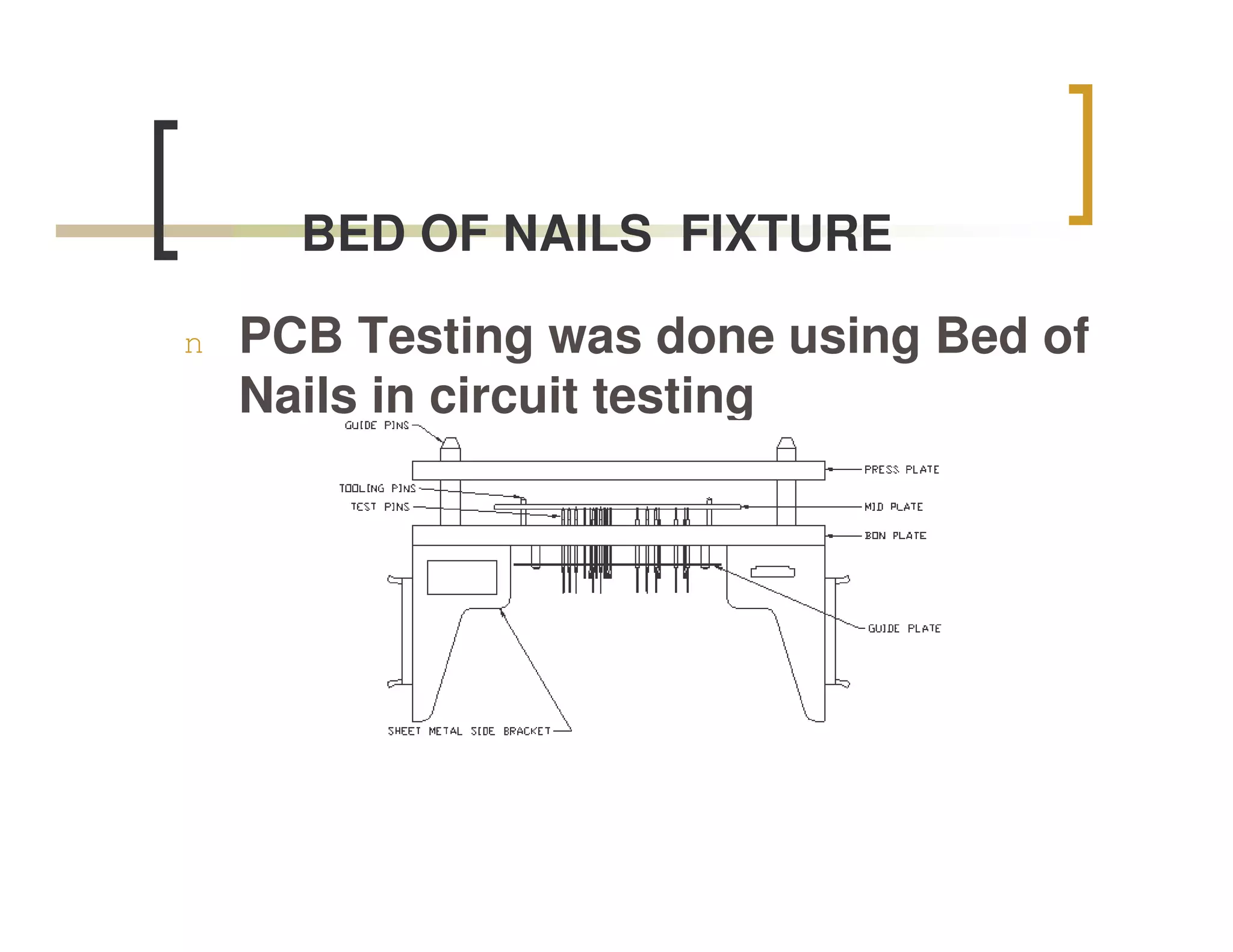
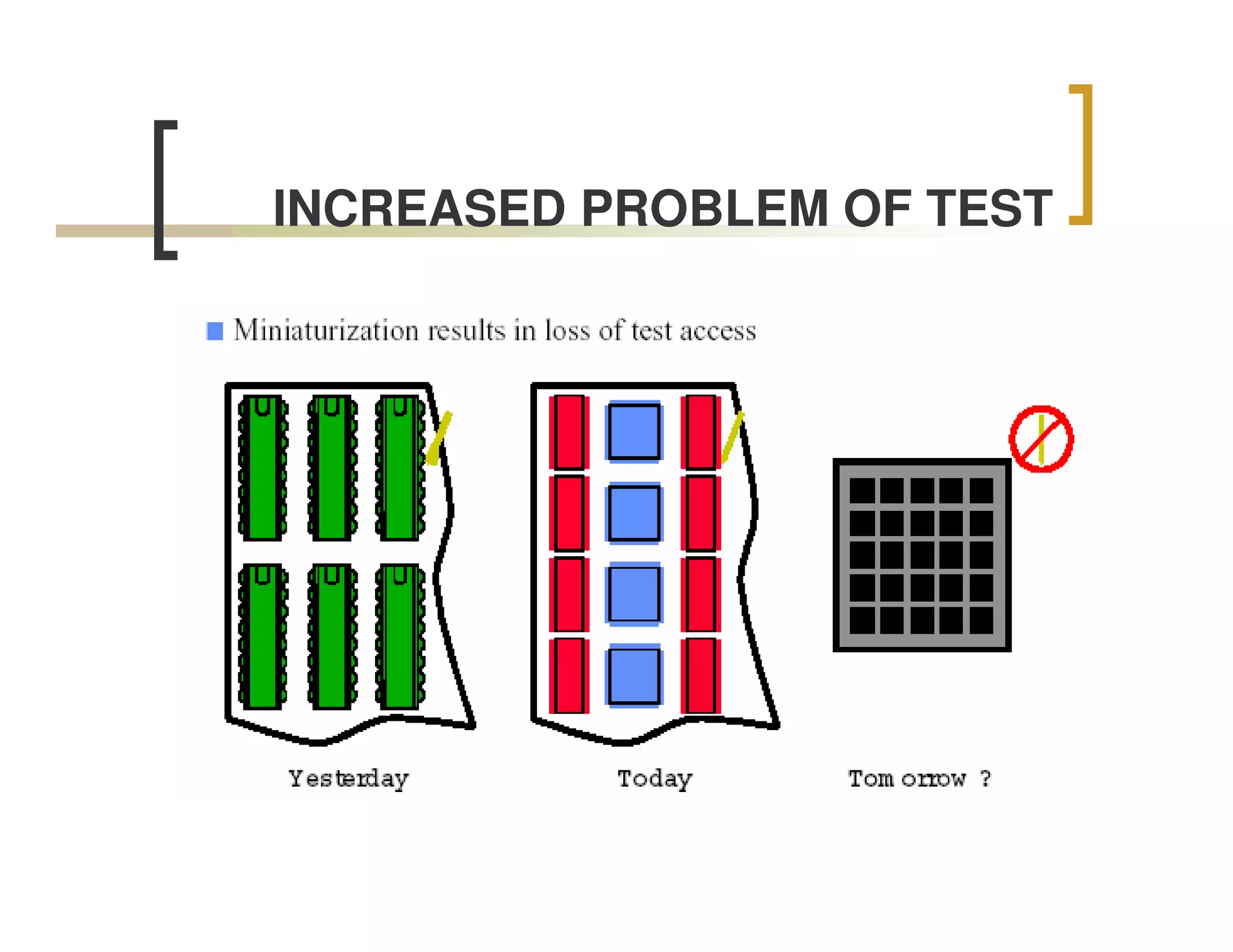
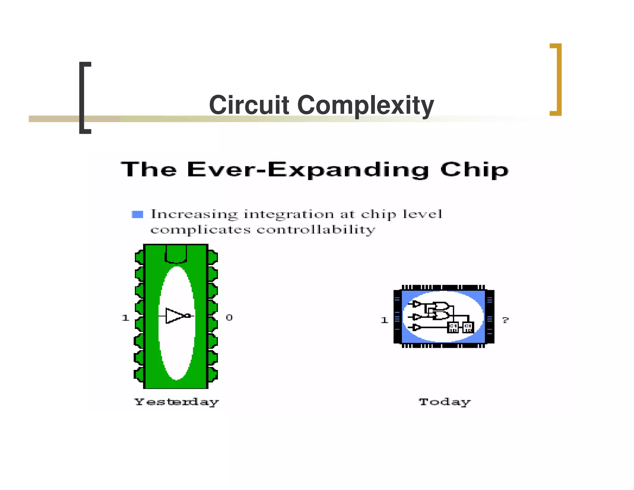
Discussion on the Bed of Nails tester for PCB testing, increased testing problems, circuit complexity, and development costs.
Introduction to IEEE 1149.1 standard, its protocols, and its use in functional, interconnect tests, and built-in self-test procedures.
Advantages of JTAG, including elimination of physical test points, reduced costs, and faster time-to-market.
Explanation of Boundary Scan methodology, its architecture, and how it works, including TAP controller and registers.
Details of the JTAG Test Access Port (TAP), including the four pins (TMS, TCK, TDI, TDO) and their functions.
Description of the JTAG TAP Controller as a finite state machine for controlling data scanning.
Information about different data registers and the standard procedure for testing devices using boundary-scan technology.
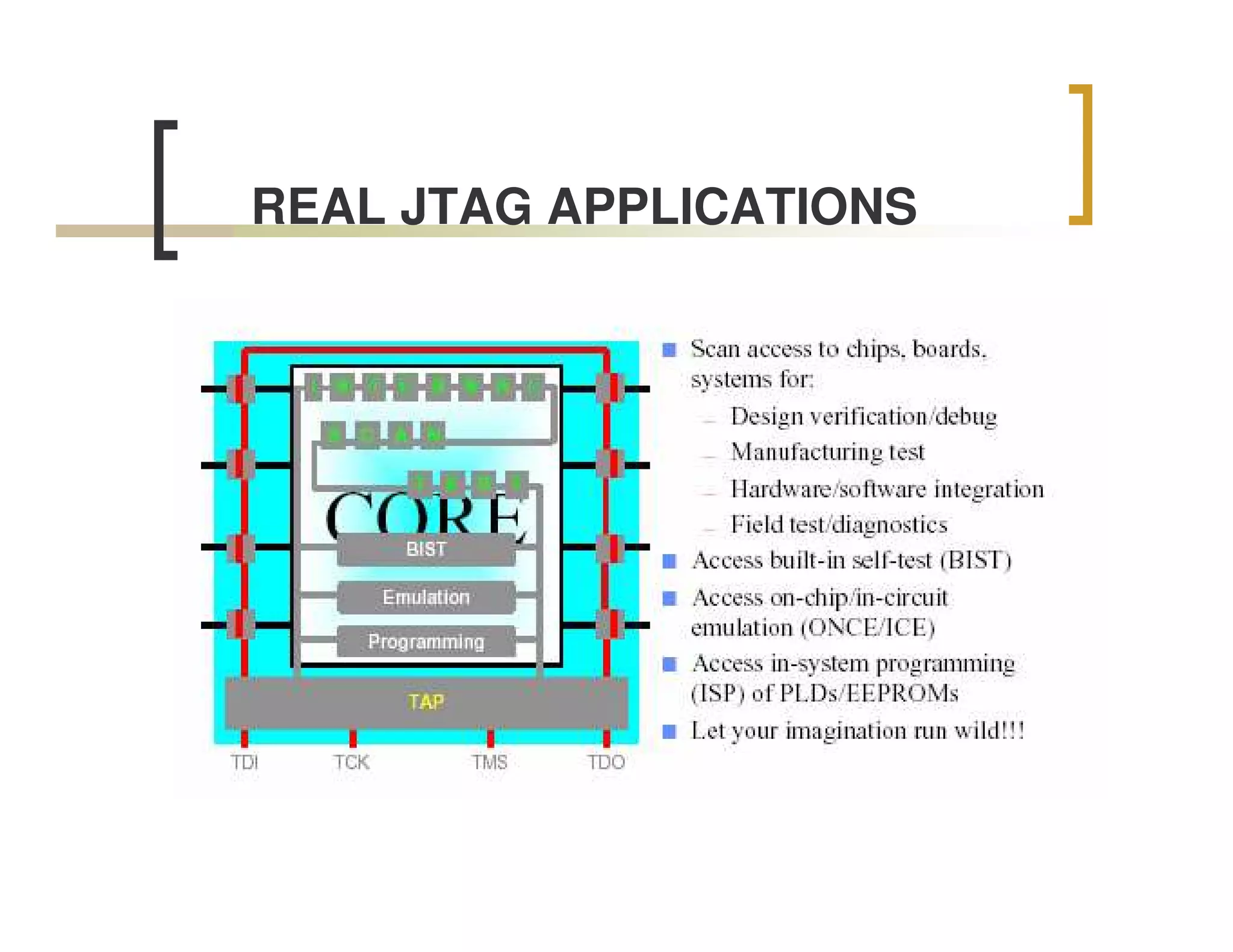
Discussion on various real-world applications of JTAG technology.
List of references and sources related to JTAG and its applications.
JTAG (1149.1 STANDARD)
IEEE 1149.1, a standard 4 wire serial protocol
protocol that established the details of access to
any chip with a JTAG port .
n Boundary scan testing of Integrated Circuits(IC’s) and boards.
n Debug Embedded devices.
n System level debug capability
8.
What can itbe used for?
The standard defines instructions that can be used to perform :
n Functional Tests
n Interconnect tests
n Built-in self test procedures.
9.
Advantages
n The need for physical test points on the board is eliminated
leading to significant savings as a result of simpler board
layouts.
n Less costly test fixtures.
n reduced time on in-circuit test systems.
n increased use of standard interfaces.
n faster time-to-market.
10.
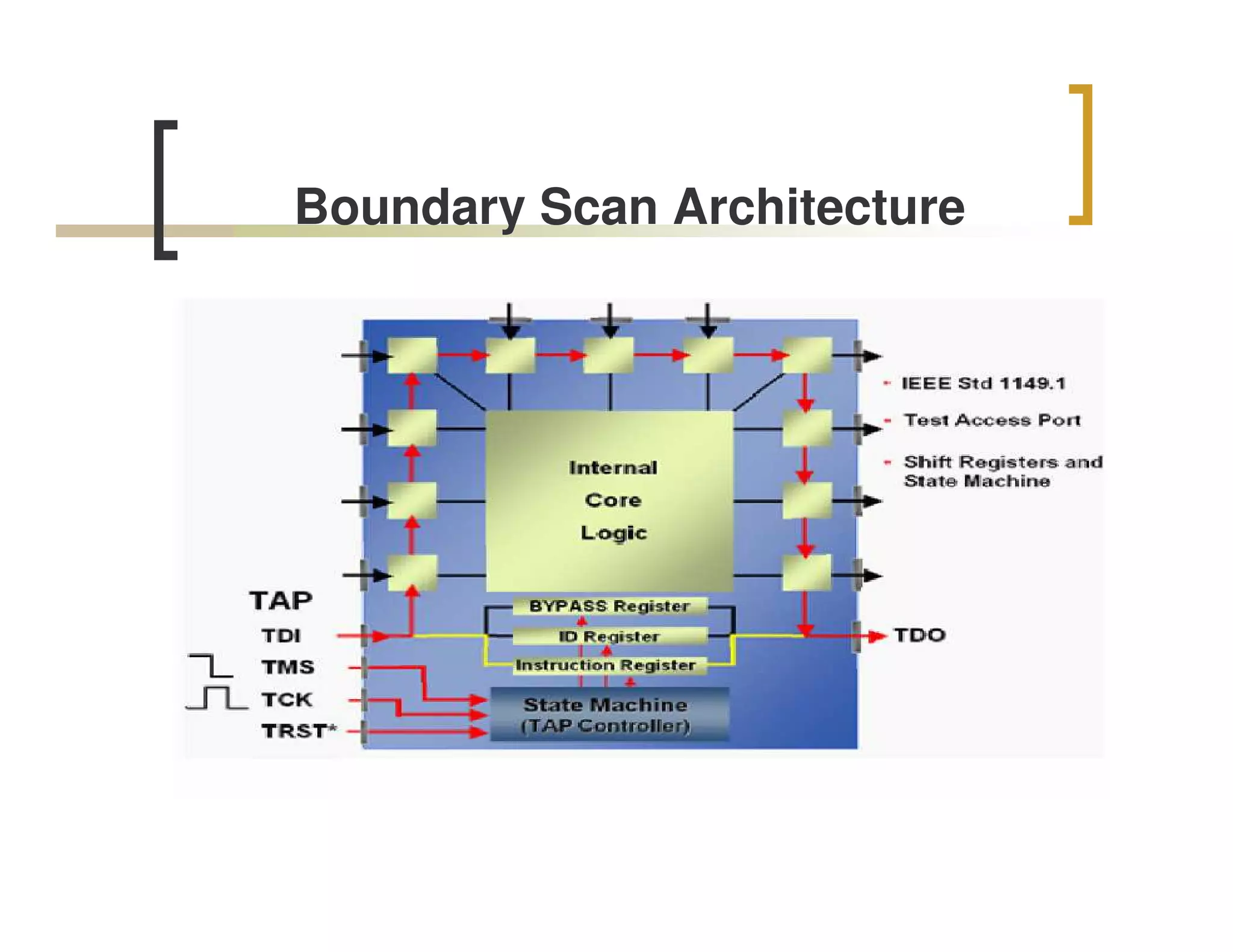
Boundary Scan
n What is Boundary Scan?
Boundary scan is a methodology allowing complete
controllability and observability of the boundary pins of a JTAG
compatible device via software control.
BOUNDARY SCAN PRINCIPLE
n How does it work?
The top level schematic of the test logic defined by IEEE Std 1149.1 includes
three key blocks:
The TAP Controller
This responds to the control sequences supplied through the test access port
(TAP) and generates the clock and control signals required for correct
operation of the other circuit blocks.
The Instruction Register
This shift register-based circuit is serially loaded with the instruction that
selects an operation to be performed.
The Data Registers
These are a bank of shift register based circuits. The stimuli required by an
operation are serially loaded into the data registers selected by the current
instruction. Following execution of the operation, results can be shifted out for
examination.
13.
JTAG Test AccessPort
n The JTAG Test Access Port (TAP) contains four pins that
drive the circuit blocks and control the operations specified.
The TAP facilitates the serial loading and unloading of
instructions and data.
The four pins of the TAP are:
n TMS – Test Mode Select
n TCK – Test Clock
n TDI - Test Data Input
n TDO – Test Data Output
14.
JTAG Test AccessPort (Contd)
The function of each TAP pin is as follows:
n TCK - this pin is the JTAG test clock. It sequences
the TAP controller as well as all of the JTAG
registers
n TMS - this pin is the mode input signal to the TAP
Controller. The state of TMS at the rising edge of
TCK determines the sequence of states for the TAP
controller.
15.
JTAG Test AccessPort
(Contd)
n TDI - this pin is the serial data input to all JTAG
instruction and data registers. TDI is sampled into the
JTAG registers on the rising edge of TCK.
n TDO - this pin is the serial data output for all JTAG instruction and
data registers.. TDO changes state on the falling edge of TCK and
is only active during the shifting of data through the device. This pin
is three-stated at all other times
16.
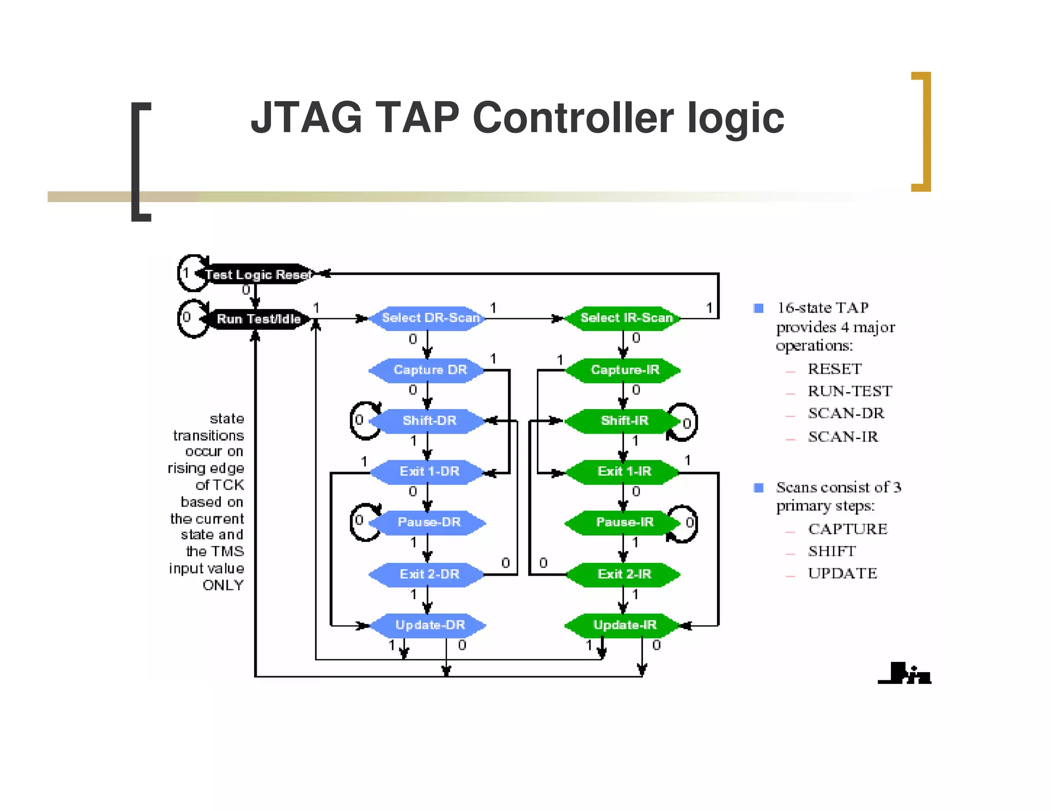
JTAG TAP Controller
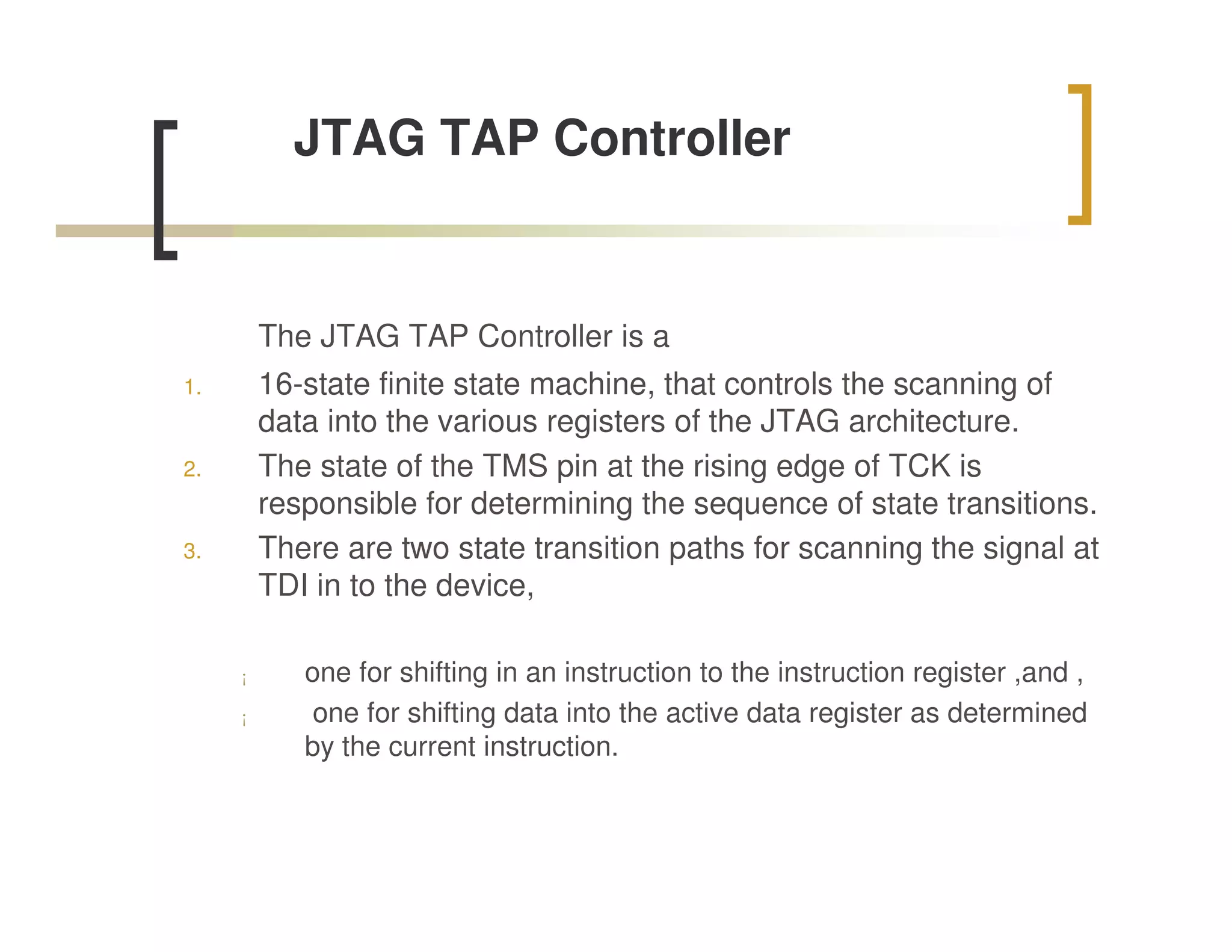
The JTAG TAP Controller is a
1. 16-state finite state machine, that controls the scanning of
data into the various registers of the JTAG architecture.
2. The state of the TMS pin at the rising edge of TCK is
responsible for determining the sequence of state transitions.
3. There are two state transition paths for scanning the signal at
TDI in to the device,
¡ one for shifting in an instruction to the instruction register ,and ,
¡ one for shifting data into the active data register as determined
by the current instruction.
Data Registers
n The Device ID register (IDR) reads-out an
identification number which is hardwired into the
chip.
n The Bypass register (BR) is a 1-cell pass-through
register which connects the TDI to the TDO with a
1-clock delay to give test equipment easy access to
another device in the test chain on the same board.
n The Boundary Scan register (BSR), intercepts all
the signals between the core-logic and the pins.
19.
Test Process
The standard test process for verifying a device or
circuit board using boundary-scan technology is as
follows:
n The tester applies test or diagnostic data on the
input pins of the device.
n The boundary-scan cells capture the data in the
boundary scan registers monitoring the input pins.
n Data is scanned out of the device via the TDO pin,
for verification.
n Data can then be scanned into the device via the
TDI pin.
n The tester can then verify data on the output pins of
the device.
References
n http://www.ee.ic.ac.uk/pcheung/teachi
ng/ee3_DSD/ti_jtag_seminar.pdf
n http://www.inaccessnetworks.com/proj
ects/ianjtag/jtag-intro/jtag-intro.html
n http://toolbox.xilinx.com/docsan/3_1i/d
ata/common/jtg/dppa/appa.htm