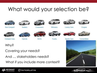
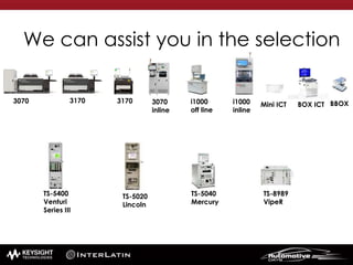
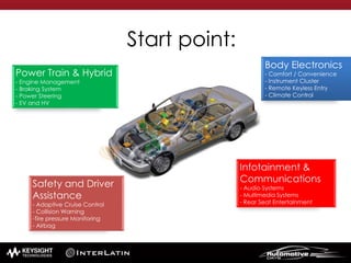
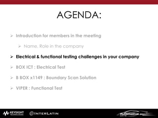
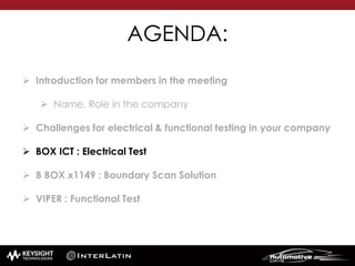
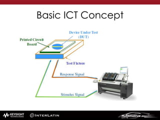
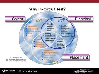
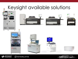
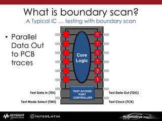
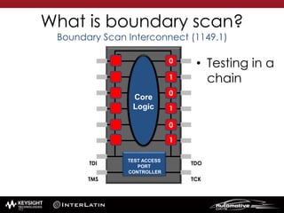
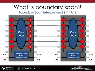
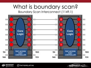
Automotive Seminar
México 2015
May 18th to May 22th
June 1st to June 5th
AGENDA:
 Introduction
 Name, Role in the company
 Electrical & functional testing challenges in your company
 BOX ICT : Electrical Test
 B BOX x1149 : Boundary Scan Solution
 VIPER : Functional Test - How to take advantage of Modular Test
Systems
AGENDA:
 Introduction
 Name, Role in the company
 Challenges for electrical & functional testing in your company
 BOX ICT : Electrical Test
 B BOX x1149 : Boundary Scan Solution
 VIPER : Functional Test
What would your selection be?
Why?
Covering your needs?
And … stakeholders needs?
What if you include more context?
3070 3170 3170
We can assist you in the selection
i1000
off line
TS-5400
Venturi
Series III
TS-5020
Lincoln
TS-5040
Mercury
TS-8989
VipeR
3070
inline
BBOXMini ICT BOX ICTi1000
inline
Body Electronics
- Comfort / Convenience
- Instrument Cluster
- Remote Keyless Entry
- Climate Control
Power Train & Hybrid
- Engine Management
- Braking System
- Power Steering
- EV and HV
Infotainment &
Communications
- Audio Systems
- Multimedia Systems
- Rear Seat Entertainment
Safety and Driver
Assistance
- Adaptive Cruise Control
- Collision Warning
-Tire pressure Monitoring
- Airbag
Start point:
AGENDA:
 Introduction for members in the meeting
 Name, Role in the company
 Electrical & functional testing challenges in your company
 BOX ICT : Electrical Test
 B BOX x1149 : Boundary Scan Solution
 VIPER : Functional Test
Electrical & Functional testing
challenges in your Company
AGENDA:
 Introduction for members in the meeting
 Name, Role in the company
 Challenges for electrical & functional testing in your company
 BOX ICT : Electrical Test
 B BOX x1149 : Boundary Scan Solution
 VIPER : Functional Test
Basic ICT Concept
• Insufficient
• Poor welding
• Marginal Joints
• Voids
• Excess
• Shorts
• Opens
• Invisible
parts
• Missing
• Gross Shorts
• Lifted Leads
• Bent Leads
•Excess
•Bridging
•Tombstone
•Misalignment
•Orientation
• Missing Non-Elec.
• Bypass Caps, L’s
• Extra Parts
• Mark Inspection
•Inverted
•Polarity
•Missing
Socketed
Parts
• Dead Part
• Wrong Part
• Bad Part
• PCB Short/Open
• Functionally Bad
Solder
Placement
Electrical
AOI
ICTAXI
ICT: In-circuit Test
AXI: Automated X-ray Inspection
AOI: Automated Optical Inspection
Why In-Circuit Test?
Keysight available solutions
ICT Low pin count applications?
2 cylinders engine
w about a Full Featured
version that
fits in your rack?
Don’t want a
Full Sized ICT system?
Full ICT Feature:
• RLC analog measurement
• Voltage measurement
• Boundary Scan Test
• Cover Extend Technology
• On Board Programming
• Digital Library Test
• SPI or I2C Programming
• Client-Server Software API
Compact ICT system with Built-in PC Controller
Supports both Analog and Hybrid Cards
Provides up to 512 test channels
Customizable in Footer 17
What if we set the rest of the car?
Box In-Circuit Test (BICT)
POWER SUPPLY
FIXTURE INTERFACE
USER INTERFACE
ALL INTERCONNECTED
CASSETTES TECHNOLOGY
Box In-Circuit Test (BICT)
You don’t need vacuum
pump or air compressor
Full ICT Feature:
• RLC analog measurement
• Voltage measurement
• Boundary Scan Test
• Cover Extend Technology
• On Board Programming
• Digital Library Test
• SPI or I2C Programming
• Client-Server Software API
Specifications
Product Features Benefits
Diagnostics Test
Set
Powerful desktop form factor
Boundary scan & on board digital tests
Easy & flexible deployment
Modular Power
system
The flexibility to mix
and match from over 30 different DC
power modules to create from 1 to
4-channel DC power system optimized
to meet specific test requirements
Fixtures Interchange cassettes
Flashing
(optional)
Nodes for connection available
i1000D Diagnostic Test Set Spec
Product Features High-performance module
Max node count 512
Max digital driver/receiver channels 256
SCPI Command Support Yes, thru LAN
External power supply control Yes, thru Agilent IO Library
Keysight VTEP 2.0 Powered Yes
On Board Programming Yes
Boundary Scan Yes, native with interconnect capabilities
Digital Test Library Support Agilent VCL
Analog component test Resistors, Capacitors, Inductors, Diodes, FET, and
Jumpers.
Voltage measurement Max 100V
Frequency measurement 200Mhz, 12 sets, with frequency mux card
Digital Driver/Receiver characteristics Mutiplexing 1:1, Unmuxed
Per-pin Programmable receiver 0 to 4.85 V
Per-pin Programmable driver 0 to 5 V
Max sink current Peak 500 mA
Max source current Peak 500 mA
Pattern rate Max 2 MPS
Programmable vector cycle Programmable
Programmable vector cycle resolution 50 ns
Programmable receive delay Programmable
Programmable receive delay resolution 10 ns
Options for N6700
N6751A High-performance module Autorange 50V, 5A, 50W
N6761A Precision DC Power Module, 50V, 1.5A, 50W
N678XA Source Measure Units (SMUs) Up to 20V, 8A, 80W
Fixture customizing
• Standard
Replacement Kit
with Intermediate
Interface Frame
(basic unit)
• Customizable for
fixture
• 2 weeks for
customizing
Options for Transfer blocks
Reader unit Option
P04-000072-01 and
P04-000073-01
STS TRANSFER SIGNAL PCB SIDE and STS TRANSFER
SIGNAL TEST SYSTEM SIDE (one pair basic unit)
P04-000070-01
and P04-000071-
01
STS TRANSFER POWER PCB SIDE and STS TRANSFER
POWER TEST SYSTEM SIDE (one pair basic unit)
P04-000082-01
and
P04-000083-01
BOX ICT TRANSFER SIGNAL PCB SIDE and BOX ICT
TRANSFER SIGNAL TEST SYSTEM SIDE(five pair basic unit)
Types of products
• Usable area: 295mmx250mm MAX PCB
size
Training
• 1. Training name: Box In-Circuit Test Training
• 2. Training manual: Box In-Circuit Test training
manual
• 3. Slides for Training : Slides
• 4. hand-on Labs: Develop Labs; Board
Demo,
• 5. Certificate Instructor
• 6. Certificate of Achievement.
• 7. Duration: 3 days
Live DEMO
PXI INSTRUMENTATION
CARD
IN CIRCUIT TESTING
Delivery Time
• If stock: 2 weeks (time for hardware
configuration)
• No stock: 8 weeks (time for fabrication
and hardware configuration)
AGENDA:
 Introduction for members in the meeting
 Name, Role in the company
 Challenges for electrical & functional testing in your company
 BOX ICT : Electrical Test
 B BOX x1149 : Boundary Scan Solution
 VIPER : Functional Test
Test Access challenges
INTENSE COST PRESSURE
• Fierce competition in the global market
• Customers expecting more functionality,
better quality and at lower cost
•Lower equipment cost
•Lower deployment cost
•Lower cost of ownership
Page 37
General ICT Challenges in the Industry
LOST OF TEST ACCESS
• Increased board functionality
• Highly dense board and design complexity
• No layout space for targets
• Finer trace-spacing routing
• Higher frequencies
0%
20%
40%
60%
80%
100%
1990 1995 2000 2005 2010 2015
In Traditional ICT,
Lost of Access = Lost
of Test Coverage
Test Access (%) over the years
The problem: Loss of testpoints
• Reasons:
1) Embedded vias
2) Embedded layers
3) 3D ICs
4) PCBA density
5) High speed signals
38
Suite of Test Point Accessibility Technology
Keysight Technology to increase coverage!!
The solution: Boundary Scan
• Bscan is one of the most effective standards to regain
test access.
1) It is a standard
2) New standards are continously developed
a) Test DDR memories
b) Functional (embedded) test
c) Analog test
3) IC test requires only a fraction of the test access.
The success of Bscan implementation in
mass production test is directly dependent
on DFT
40
INTRODUCTION TO …
KEYSIGHT X1149
BOUNDARY SCAN ANALYZER
41
IEEE 1149.6
IEEE 1149.1
IEEE 1581
JTAG
TCK TMS
TDI
TDO
TRST
42
What is boundary scan?
A Typical IC
• Testing requires knowledge of the device
functionality
101010
101010
101010
101010
101010
101010
Core
Logic
101010
101010
101010
101010
101010
101010
43
What is boundary scan?
A Typical IC … adding boundary scan
• Core logic
is isolated
TEST ACCESS
PORT
CONTROLLER
Core
Logic
Test Data Out (TDO)
Test Clock (TCK)
Test Data In (TDI)
Test Mode Select (TMS)
Boundary Scan
Cells
44
What is boundary scan?
A Typical IC … testing with boundary scan
• Serial Data In
TEST ACCESS
PORT
CONTROLLER
Core
Logic
0
0
0
1
1
1
10010 1
Test Data Out (TDO)
Test Clock (TCK)
Test Data In (TDI)
Test Mode Select (TMS)
45
What is boundary scan?
A Typical IC … testing with boundary scan
• Serial Data
Out
TEST ACCESS
PORT
CONTROLLER
Core
Logic
0
0
0
1
1
11
0
0
1
0
1
Test Data Out (TDO)
Test Clock (TCK)
Test Data In (TDI)
Test Mode Select (TMS)
46
What is boundary scan?
A Typical IC … testing with boundary scan
• Parallel
Data Out
to PCB
traces
TEST ACCESS
PORT
CONTROLLER
Core
Logic
0
0
0
1
1
1
Test Data Out (TDO)
Test Clock (TCK)
Test Data In (TDI)
Test Mode Select (TMS)
1
0
0
1
0
1
47
What is boundary scan?
Boundary Scan Interconnect (1149.1)
• Testing in a
chain
TEST ACCESS
PORT
CONTROLLER
Core
Logic
0
0
0
1
1
1
TDO
TCK
TDI
TMS
48
What is boundary scan?
Boundary Scan Interconnect (1149.1)
TEST ACCESS
PORT
CONTROLLER
Core
Logic
0
0
0
1
1
1
TDO
TCK
TDI
TMS
TEST ACCESS
PORT
CONTROLLER
Core
Logic
TDO
TCK
TDI
TMS
49
What is boundary scan?
Boundary Scan Interconnect (1149.1)
TEST ACCESS
PORT
CONTROLLER
Core
Logic
0
0
0
1
1
1
TDO
TCK
TDI
TMS
TEST ACCESS
PORT
CONTROLLER
Core
Logic
0
0
0
1
1
1
TDO
TCK
TDI
TMS
1
0
0
1
0
1
50
What is boundary scan?
Boundary Scan Interconnect (1149.1)
• One port controls the tests in the chain
TEST ACCESS
PORT
CONTROLLER
Core
Logic
0
0
0
1
1
1
TDO
TCK
TDI
TMS
TEST ACCESS
PORT
CONTROLLER
Core
Logic
0
0
0
1
1
1
TDO
TCK
TDI
TMS
1
0
0
1
0
1
51
• For High-speed Differential signals, with AC coupling
caps
++
− −
What is boundary scan?
Boundary Scan Interconnect (1149.6)
TEST ACCESS
PORT
CONTROLLER
Core
Logic
TDO
TCK
TDI
TMS
TEST ACCESS
PORT
CONTROLLER
Core
Logic
TDO
TCK
TDI
TMS
0
1
0
1
01
0
1 0
1
53
• Testing each driver separately
What is boundary scan?
Buswire
TEST ACCESS
PORT
CONTROLLER
Core
Logic
TDO
TCK
TDI
TMS
TEST ACCESS
PORT
CONTROLLER
Core
Logic
TDO
TCK
TDI
TMS
1 1
1
1 1
++
− −
54
• Testing each driver seperately
What is boundary scan?
Buswire
TEST ACCESS
PORT
CONTROLLER
Core
Logic
TDO
TCK
TDI
TMS
TEST ACCESS
PORT
CONTROLLER
Core
Logic
TDO
TCK
TDI
TMS
1
1
1
1
1
++
− −
55
• Opens test: Expect “natural” state
What is boundary scan?
Pull Up/Down Resistors
TEST ACCESS
PORT
CONTROLLER
Core
Logic
TDO
TCK
TDI
TMS
TEST ACCESS
PORT
CONTROLLER
Core
Logic
TDO
TCK
TDI
TMS
1
0
1
++
− −
GND
VCC
high
low
0
56
• Opens Fault
What is boundary scan?
Pull Up/Down Resistors
TEST ACCESS
PORT
CONTROLLER
Core
Logic
TDO
TCK
TDI
TMS
TEST ACCESS
PORT
CONTROLLER
Core
Logic
TDO
TCK
TDI
TMS
0
0
0
++
− −
GND
low
0
low
VCC
57
• Shorts test: Expect driven state
What is boundary scan?
Pull Up/Down Resistors
TEST ACCESS
PORT
CONTROLLER
Core
Logic
TDO
TCK
TDI
TMS
TEST ACCESS
PORT
CONTROLLER
Core
Logic
TDO
TCK
TDI
TMS
0
1
++
− −
GND
VCC
high
low
0
1
0
1
0
1
58
• Shorts fault
What is boundary scan?
Pull Up/Down Resistors
TEST ACCESS
PORT
CONTROLLER
Core
Logic
TDO
TCK
TDI
TMS
TEST ACCESS
PORT
CONTROLLER
Core
Logic
TDO
TCK
TDI
TMS
1
1
++
− −
GND
high
low
0
1
VCC
1
0
1
1
59
What is boundary scan?
Silicon Nails Test
• Testing non-Boundary Scan ICs
TEST ACCESS
PORT
CONTROLLER
Core
Logic
TDO
TCK
TDI
TMS
TEST ACCESS
PORT
CONTROLLER
Core
Logic
TDO
TCK
TDI
TMS
++
− −
GND
VCC
01
1
0
111
0
1
60
What is boundary scan?
Cover-Extend Technology (CET)
• Testing non-Boundary Scan ICs; Vectorless test method
TEST ACCESS
PORT
CONTROLLER
Core
Logic
TDO
TCK
TDI
TMS
TEST ACCESS
PORT
CONTROLLER
Core
Logic
TDO
TCK
TDI
TMS
++
− −
GND
VCC
1
0
1
61
APPLICATIONS OF KEYSIGHT X1149
BOUNDARY SCAN ANALYZER
70
U1
TDI TDO
U4
TDI TDO
U5
TDI TDO
U3
TDI TDO
What if … ?
• Normal circuit
board
• Select the Bscan
components
• Wire the Bscan
components into
same voltage levels
chains
U2
J1
U6
J2
J3
3.3V
5V
71
U1
TDI TDO
U4
TDI TDO
U5
TDI TDO
U3
TDI TDO
What if … ?
• Normal circuit
board
• Select the Bscan
components
• Wire the Bscan
components into
same voltage
levels chains
• Interconnected
nodes can be
tested even
without testpoints
U2
J1
U6
J2
J3
3.3V
5V
72
• Add a test box
controlled by PC
U4
TDI TDO
U1
TDI TDO
U6U5
TDI TDO
U3
TDI TDO
What if … ? … Then we …
U2
J1
J2
J3
3.3V
5V
TAP 1
CET
TAP 2
73
• Test box outputs clear
failure messages for
simple failure diagnosis
U4
TDI TDO
U1
TDI TDO
U6U5
TDI TDO
U3
TDI TDO
What if … ? … Then we …
U2
J1
J2
J3
3.3V
5V
Board Failed
#1 Open Failure at U4.62
Expected: 10011010
Actual: 00000000
#2 Voltage Failure on “3.3V”
Measured: 0.0V
High: 3.4V
Low: 3.2V
Expected:
Actual:
TAP 1
CET
TAP 2
74
• Add voltage
monitoring
• Add vectorless
testing
U4
TDI TDO
U1
TDI TDO
U6U5
TDI TDO
U3
TDI TDO
U2
J1
J2
J3
3.3V
5V
Board Failed
#1 Open Failure at U4.62
Expected: 10011010
Actual: 00000000
#2 Voltage Failure on “3.3V”
Measured: 0.0V
High: 3.4V
Low: 3.2V
Expected:
Actual:
TAP 1
CET
TAP 2
75
• … we have the
solution
• NOW
U4
TDI TDO
U1
TDI TDO
U6U5
TDI TDO
U3
TDI TDO
What if … ? … Then we …
U2
J1
J2
J3
3.3V
5V
Board Failed
#1 Open Failure at U4.62
Expected: 10011010
Actual: 00000000
#2 Voltage Failure on “3.3V”
Measured: 0.0V
High: 3.4V
Low: 3.2V
Expected:
Actual:
TAP 1
CET
TAP 2
76
• X1149.6
• CET
U4
TDI TDO
U1
TDI TDO
U6U5
TDI TDO
U3
TDI TDO
Maximizing coverage
U2
J1
J2
J3
3.3V
5V
Board Failed
#1 Open Failure at U4.62
Expected: 10011010
Actual: 00000000
#2 Voltage Failure on “3.3V”
Measured: 0.0V
High: 3.4V
Low: 3.2V
Expected:
Actual:
TAP 1
CET
TAP 2
77
Boundary Scan Test Coverage Example
Possible: Test Coverage > 50% of total nodes tested
Total Nodes
tested
%
Interconnect 3094 31.9
Interconnect
dot6
516 5.3
Bus wire 727 7.5
Pull up / down
resistors
200 2.1
Silicon Nails 1800 18.6
Cover-Extend 100 1.0
Total 6237 64.3
Network Communications board
9700 nodes
1800 18.6
78
COMPLETE BUNDLE AVAILABLE.
• PC Controlled (Ethernet).
• Four TAP/IO Boxes.
- 1x TAP Port.
- 4x Digital input ports.
- 5x Digital output ports.
• One Diagnostic Clip.
• Add-on Cover-Extend Technology
capability
- Vectorless testing of ICs or Connectors through
boundary scan
• Scan Path Linker
- Connecting physically separated chains to test
the interconnecting nets
Controller
TAP I/O Boxes
Diagnostic
Clip
x1149 CET Mux
Power Adaptor
LAN to PC
x1149 TAP/IO
x1149 Controller
No test access
Cover Extend Technology uses Boundary Scan as the stimulus to
test non-Boundary Scan components having no test access.
VTEP amplifier, sensor plate and a Cover-Extend Mux
is required to complete the metrology.
VTEP amplifier
& sensor plate
Graphical view of the selected
chain. Mouse over to retrieve
the TAP information.
All information of the
devices in the chain at
a glance.
Process Outline
Guides user through
test development and
debug.
Project Explorer
Navigate to sections
of the test at a click.
Click to select
chain.
Generate Multi-Chain
Scan Path Linker combines
chains at a click.
Configure/Reconfigure Chain
Automatically sets up chains
using board’s net information.
View the failing test in Waveform Viewer or the
Frame Debugger to view the expected vs actual.
View failure as a waveform
View the failing test in Waveform Viewer or the
Frame Debugger to view the expected vs actual.
Vector view of frame
Undocked view of the waveform
View the failing test in Waveform Viewer or the
Frame Debugger to view the expected vs actual.
Undocked view of the
frame
Output
Shows the results of all the tests for the chain(s).
Results of tests are highlighted in colors. Test
results can be sorted by clicking on the title tab.
Repair Ticket
Pin-level failure reporting and possible cause.
Output
Shows the results of all the tests for the chain(s).
Results of tests are highlighted in colors. Test
results can be sorted by clicking on the title tab.
Repair Ticket
Pin-level failure reporting and possible cause.
Board with injected open faults (Dot6 test)
CET test failures
‘Standard’ Boundary Scan Test
• Board designs can have boundary scan chains
physically separated (not connected).
• Such boundary chains will be generated and tested
as separate chains.
Scan Path Linker
• Boundary scan test coverage can be increased by
the number of interconnect nets if boundary scan
chains can be ‘connected’ during testing and
revert to its original design after testing.
• x1149 Scan Path Linker connects two or more
boundary scan chains by linking the TDO to the TDI
of these chains inside the controller.
• Automated logic level management
IC IC
IC IC
No test coverage
IC IC
IC IC
Nets tested
Integrated STAPL Player
• STAPL (Standard Test and
Programming Language)
• JEDEC standard : JEDEC-JESD71
• Enables programming of various
CPLD/FPGA devices from different
vendors like Xilinx, Altera, Lattice,
Actel (Microsemi) and more.
• The compiler accepts various
formats : STAPL, jam, jbc, svf files
USING X1149 IN ALL STAGES OF
THE PRODUCT LIFE CYCLE
92
x1149 throughout the Product Cycle
Design R&D
• Quick test turn on
• Test high-value ICs
• Diagnostics during design verification
Warranty Repair
• Field Repair
• Fixtureless, portable
Prototyping NPI
• Quick test turn on
• Test high-value ICs
• Test development enhancements
Mass Production Production
• Leverage from NPI
• ICT or Standalone integration
• Savings on fixturing
Debug Repair
• Short test time
• Pin level diagnostics
Product Life Team Benefits
93
Conclusion
• Boundary Scan is the most effective method to reduce
the issues regarding loss of test access on the product.
• Boundary Scan requires DFT to be more effective
• Keysight produces an easy to use, manufacturing
ready boundary scan tester for your production
Get it NOW
94
AGENDA:
 Introduction for members in the meeting
 Name, Role in the company
 Challenges for electrical & functional testing in your company
 BOX ICT : Electrical Test
 B BOX x1149 : Boundary Scan Solution
 VipeR : Functional Test
How to take advantage of
Modular Test Systems
What is PXI?
The PCI eXtensions for
Instrumentation (PXI)
modular
instrumentation
architecture delivers a
rugged, PC-based, and
high-performance
measurement and
automation system.
The PXI Systems Alliance
(PXISA) is an industry
consortium that
promotes and
maintains the PXI
Standard.
VXI or PXI?
Description PXIe VXI Benefit to YOU
Data transfer rate
up to 8GB/s (to system
slot)
up to 4GB/s (slot to slot)
PXI-5 PXI Express
hardware specification
up to 320Mb/s
(VXIbus Spec, Rev 1.4)
Larger bandwidth for
future applications
support
(e.g. infotainment,
telematics, radar)
Mainframe size 4U (M9018A) 8U (E8401A)
More rack space in
system for other
instruments
(e.g. 2 PXI chassis in the
future, more power
supplies)
No. of slots in
mainframe
18 slots (M9018A) 13 slots (up to C-Size)
More instruments can
be added to chassis
improving
instrument density in
system
Why to use Modular
Instrumentation in ATE
Systems?
 Users standardize
cards and card
cages, so they can
configure systems as
needed.
 Based on the PC
architecture, so
software is readily
available.
 Lots of development
work is currently under
way on PXI cards.
 PXI is fast and costs
less than VXI.
A Typical Production Line
Structure
The right solution for right application
Complexity100 Pins 200 Pins
Price
Body Control
Dashboard
EPB
Fuel Control
Telematics
LED Driver
Sensor
ABS
Sensor
Door
LED Driver
Telematics
EPB
Clusters
Fuel Control
Transmission Control Power Train ECU
Body Control
Key
Simple BCM
Immobilizer
ECU
RKE
Immobilizer
TS-8989
VipeR
TS-5040
Mercury
TS-5020
Lincoln
TS-5400
Venturi SIII
Brushless
Motor Controller
Lighting
Infotainment
PXI , GPIB, LXI
Instruments support
Switch Load Unit
U8989A
VipeR
Lead time: 8 weeks
Warranty period: 1 years
U8989A (TS8989 VipeR)
World’s only INTEGRATED
HIGH-CURRENT SWITCH
WITH PXI-BASED
MEASUREMENT SYSTEM IN
A BOX!
Integrated
PXI Chassis
and
Switch/Load
platform
102
Up to 104 pin counts
Suitable for Functional test of Mechatronics
applications with high Current and voltage
ranges (ideal for Automotive)
Up to 40A current loads
No Rack: It can be setup as bench top
system or integrated into a Rack & Stack
system
TS-5000 Embedded PC controller - Core i7
2.1GHz processor, 8GB S-DIMM, 500GB
HDD SATA, 2x Gigabit Ethernet ports, 4x
USB 2.0 ports and 2x USB 3.0 ports with
Built-in GPIB controller,
Windows 7, Keysight IO 64-bit, TxSL v7 and
TS-5000 v7
VIPER CONCEPT DESIGN
FIXTURE INTERFACE
VIPER INSTRUMENTATION
POWER SUPPLY
Agilent PXI , GPIB & LXI
Instruments
Switch Load Unit
Modular Power SuppliesMacpanel Bocks & Cabling
U8972A
N3300 E-Load
Lead time: 8 weeks
Warranty period: 1 years
Up to 464 pin counts
Up to 40A current loads
2.0m rack with solid door and extractor fan
3-Phase only PDU with EMO switch
Power Distribution Unit (PDM)
Thermistor
IPC backplane, CPU i5-2400, RAM 8GB, HDD
500GB
Windows 7, Keysight IO, TestExec SL 7.1, TS-5000
7.1
210 pin & 64 hi-power ICA blocks & cabling
N3300A eLoad mainframe & modules
1kW, 2kW and 400W Modular Power Supplies
U8972A (TS5400 Venturi-SIII)
Electronic Control Unit (ECU)
CPU
Input
Buffers
Output
Drivers
Output
Drivers
Output
Drivers
Output
Driver
Driver
Input
Buffers
Inputs:
Sensors, & switch
inputs
Outputs:
Actuators, motors, lamps
and others
CAN, LIN, K-LINE,
and others
Motors
Motors
Lamps
Lamps
Relays
Relays
Other
ECU’s
sensor
sensor
sensor
sensor
sensor
switch
switch
switch
switch
Position sensor
Force Sensor
Wheel Speed Sensor
DUT communication
Actuators
Motors
Lamps
Knock Sensor
Actuators
Actuators
Electronic Control Unit (ECU)
(EPB, Simple BCM, Steering Control Unit)
Statistic shows that 1 out of 4 stolen vehicles are stolen by professional
thieves. The majority of vehicles are stolen by opportunistic thieves relying
on finding older vehicles that have ineffective security or no security at all.
Immobilizers have been mandatory in all new cars sold in
Germany since 1 January 1998
United Kingdom since 1 October 1998
Finland since 1998
Australia since 2001
Canada since 2007
Example #1 - Immobilizer
Prevent - Hot WirePrevent - Duplicate Key
Application#1 - Immobilizer
 Pin Matrix + DMM
• Relay Switching for test nodes
• Internal Voltage Measurement
• Coil Output Frequency Measurement
• Current Measurement
 Load Card + Power Supply
• Relay Switching for power supply
input and GND
• Battery Supply to Immobilizer
VBatt
Gnd
Voutput
Signal Input
Data
Code
1A 5V
 HV-DAQ
• Data Acquisition of data line
output from Immobilizer
131kHz
Example #2 – Simple Body Control
Body control module is
responsible for monitoring and
controlling various electronic
accessories in a vehicle's
body.
The BCM communicates with
other on-board computers
and its main application is
controlling load drivers –
actuating relays that in turn
perform actions in the vehicle
such as locking the doors or
dimming the salon overhead
lamp.
Application#2 – Simple Body Control
Gnd
VBatt
Switches Input
Cargo/Room
Lamps etc…
Door/Window
Locks…
Wiper/Washer
Motors…
8A
5A
4A
40A
1A
 Pin Matrix + DMM
• Switching for all test nodes
• All Voltage/Current Measurement
• All Resistance Measurement
 Load Card 40A + TITAN Power
Supply
• Relay Switching for power supply
• Battery Supply to Body Control
Module
 Various Load Card
• Different load card for external load connection
(E6176A 7.5A, U7179A 15A etc…)
• Pull Up/Down Passive Load to Vbatt or GND
 2A Load Card
• Low current load card for discrete input
(example U7177A or N9377A)
• Pull Up/Down Passive Load to Vbatt or GND
Value Proposition
Signal
Conditioning
Value #1 – Large Voltages PXI Instrument
M9186A PXI Voltage / Current Source (2 slot)
•LARGE V/I RANGE: 100V output, 200mA output which is
suitable for automotive application
•SENSE INPUT: highly accurate voltage / current output with
sense line
•No external amplification needed!
M9185A PXI D/A Converter (2 & 3 slot)
•HIGH RANGE with REMOTE SENSE: 16V output, 20mA
output with better output accuracy
•ISOLATED CHANNELS: independent channels and able to
stack up to achieve higher voltages.
•Application examples: Static Analog Input
M9188A PXI Dynamic D/A Converter (1 slot)
(Ship on Q3 15)
•16 bits resolution up to 500kSa/s output waveform update
rate
•Output unipolar voltage up to +30V
•Output current up to +20mA
•SIMULTANEOUS 16 Channels isolated banks per 4 channels
•Application examples: Dynamic Analog Input
(voltage/current)
+100V
+16V
+30V
30V for
truck
application
16V for
most vehicle
application
Value #2 – System can Accept PXI Standard
Cards from different Vendors
Value #3 – Heavy Duty Switch Load Unit &
Loadcards
Matrix Card
Switching speed as fast
as 300us
Auxiliary or direct row
access relays on each
row for DIO or DAC input
Independently
switchable series
resistance protection on
each row.
Value #3 – Continue…
Supports currents up to 40A
Every card allows connection to
defined load internally/externally
High current load cards with fuse
and fly-back protection for each
channel
Single load / Multi-load
configuration) for multiple loads
application
Load Card
DUT
40A
DUT
Aux
Inst
Value #4 – Keysight Differentiators:
Mature Platform (+20 Years), Standardization and
Global Support for SW and HW Sustaining
Value #5 –KEYSIGHT Test Exec SL Integration
supporting C#, .NET, LabView, LabWindos/CVI
Code
Graphical User Interface
IVI-C Drivers VISA
Instrument
Specific DLL
PXI Modules (eg
M9183A, M9185A)
Standalone Instrument (eg
N67xx Power Supplies, e-load)
Switch/Load Unit
(eg E6198B,
E6176A)
PCIebus
LAN/GPIB
USB
LAN/GPIB
Value #6 – Functional Test Automation
Turn Key Integration & Training by Interlatin
Hardware Software
Fixture Development
SW & HW Integration
+
TS-54XX
Training
People
VipeR-CAN
Live Demo
Direct connect between system
to simple BCM for Bench Top
development.
We are sending in real time
commands to the BCM to enter
the diagnostic mode and to
activate a motor output with a
resistive load to simulate the real
motor,
QUESTIONS?
Thank you

Automotive Days 2015 by InterLatin &

  • 1.
    Automotive Seminar México 2015 May18th to May 22th June 1st to June 5th
  • 2.
    AGENDA:  Introduction  Name,Role in the company  Electrical & functional testing challenges in your company  BOX ICT : Electrical Test  B BOX x1149 : Boundary Scan Solution  VIPER : Functional Test - How to take advantage of Modular Test Systems
  • 3.
    AGENDA:  Introduction  Name,Role in the company  Challenges for electrical & functional testing in your company  BOX ICT : Electrical Test  B BOX x1149 : Boundary Scan Solution  VIPER : Functional Test
  • 4.
    What would yourselection be? Why? Covering your needs? And … stakeholders needs? What if you include more context?
  • 5.
    3070 3170 3170 Wecan assist you in the selection i1000 off line TS-5400 Venturi Series III TS-5020 Lincoln TS-5040 Mercury TS-8989 VipeR 3070 inline BBOXMini ICT BOX ICTi1000 inline
  • 6.
    Body Electronics - Comfort/ Convenience - Instrument Cluster - Remote Keyless Entry - Climate Control Power Train & Hybrid - Engine Management - Braking System - Power Steering - EV and HV Infotainment & Communications - Audio Systems - Multimedia Systems - Rear Seat Entertainment Safety and Driver Assistance - Adaptive Cruise Control - Collision Warning -Tire pressure Monitoring - Airbag Start point:
  • 7.
    AGENDA:  Introduction formembers in the meeting  Name, Role in the company  Electrical & functional testing challenges in your company  BOX ICT : Electrical Test  B BOX x1149 : Boundary Scan Solution  VIPER : Functional Test
  • 8.
    Electrical & Functionaltesting challenges in your Company
  • 9.
    AGENDA:  Introduction formembers in the meeting  Name, Role in the company  Challenges for electrical & functional testing in your company  BOX ICT : Electrical Test  B BOX x1149 : Boundary Scan Solution  VIPER : Functional Test
  • 10.
  • 11.
    • Insufficient • Poorwelding • Marginal Joints • Voids • Excess • Shorts • Opens • Invisible parts • Missing • Gross Shorts • Lifted Leads • Bent Leads •Excess •Bridging •Tombstone •Misalignment •Orientation • Missing Non-Elec. • Bypass Caps, L’s • Extra Parts • Mark Inspection •Inverted •Polarity •Missing Socketed Parts • Dead Part • Wrong Part • Bad Part • PCB Short/Open • Functionally Bad Solder Placement Electrical AOI ICTAXI ICT: In-circuit Test AXI: Automated X-ray Inspection AOI: Automated Optical Inspection Why In-Circuit Test?
  • 12.
  • 13.
    ICT Low pincount applications? 2 cylinders engine
  • 15.
    w about aFull Featured version that fits in your rack? Don’t want a Full Sized ICT system?
  • 16.
    Full ICT Feature: •RLC analog measurement • Voltage measurement • Boundary Scan Test • Cover Extend Technology • On Board Programming • Digital Library Test • SPI or I2C Programming • Client-Server Software API Compact ICT system with Built-in PC Controller Supports both Analog and Hybrid Cards Provides up to 512 test channels
  • 17.
    Customizable in Footer17 What if we set the rest of the car?
  • 18.
    Box In-Circuit Test(BICT) POWER SUPPLY FIXTURE INTERFACE USER INTERFACE ALL INTERCONNECTED CASSETTES TECHNOLOGY
  • 19.
    Box In-Circuit Test(BICT) You don’t need vacuum pump or air compressor
  • 20.
    Full ICT Feature: •RLC analog measurement • Voltage measurement • Boundary Scan Test • Cover Extend Technology • On Board Programming • Digital Library Test • SPI or I2C Programming • Client-Server Software API
  • 21.
    Specifications Product Features Benefits DiagnosticsTest Set Powerful desktop form factor Boundary scan & on board digital tests Easy & flexible deployment Modular Power system The flexibility to mix and match from over 30 different DC power modules to create from 1 to 4-channel DC power system optimized to meet specific test requirements Fixtures Interchange cassettes Flashing (optional) Nodes for connection available
  • 22.
    i1000D Diagnostic TestSet Spec Product Features High-performance module Max node count 512 Max digital driver/receiver channels 256 SCPI Command Support Yes, thru LAN External power supply control Yes, thru Agilent IO Library Keysight VTEP 2.0 Powered Yes On Board Programming Yes Boundary Scan Yes, native with interconnect capabilities Digital Test Library Support Agilent VCL Analog component test Resistors, Capacitors, Inductors, Diodes, FET, and Jumpers. Voltage measurement Max 100V Frequency measurement 200Mhz, 12 sets, with frequency mux card Digital Driver/Receiver characteristics Mutiplexing 1:1, Unmuxed Per-pin Programmable receiver 0 to 4.85 V Per-pin Programmable driver 0 to 5 V Max sink current Peak 500 mA Max source current Peak 500 mA Pattern rate Max 2 MPS Programmable vector cycle Programmable Programmable vector cycle resolution 50 ns Programmable receive delay Programmable Programmable receive delay resolution 10 ns
  • 23.
    Options for N6700 N6751AHigh-performance module Autorange 50V, 5A, 50W N6761A Precision DC Power Module, 50V, 1.5A, 50W N678XA Source Measure Units (SMUs) Up to 20V, 8A, 80W
  • 24.
    Fixture customizing • Standard ReplacementKit with Intermediate Interface Frame (basic unit) • Customizable for fixture • 2 weeks for customizing
  • 25.
    Options for Transferblocks Reader unit Option P04-000072-01 and P04-000073-01 STS TRANSFER SIGNAL PCB SIDE and STS TRANSFER SIGNAL TEST SYSTEM SIDE (one pair basic unit) P04-000070-01 and P04-000071- 01 STS TRANSFER POWER PCB SIDE and STS TRANSFER POWER TEST SYSTEM SIDE (one pair basic unit) P04-000082-01 and P04-000083-01 BOX ICT TRANSFER SIGNAL PCB SIDE and BOX ICT TRANSFER SIGNAL TEST SYSTEM SIDE(five pair basic unit)
  • 26.
    Types of products •Usable area: 295mmx250mm MAX PCB size
  • 27.
    Training • 1. Trainingname: Box In-Circuit Test Training • 2. Training manual: Box In-Circuit Test training manual • 3. Slides for Training : Slides • 4. hand-on Labs: Develop Labs; Board Demo, • 5. Certificate Instructor • 6. Certificate of Achievement. • 7. Duration: 3 days
  • 28.
  • 29.
    Delivery Time • Ifstock: 2 weeks (time for hardware configuration) • No stock: 8 weeks (time for fabrication and hardware configuration)
  • 30.
    AGENDA:  Introduction formembers in the meeting  Name, Role in the company  Challenges for electrical & functional testing in your company  BOX ICT : Electrical Test  B BOX x1149 : Boundary Scan Solution  VIPER : Functional Test
  • 31.
  • 32.
    INTENSE COST PRESSURE •Fierce competition in the global market • Customers expecting more functionality, better quality and at lower cost •Lower equipment cost •Lower deployment cost •Lower cost of ownership Page 37 General ICT Challenges in the Industry LOST OF TEST ACCESS • Increased board functionality • Highly dense board and design complexity • No layout space for targets • Finer trace-spacing routing • Higher frequencies 0% 20% 40% 60% 80% 100% 1990 1995 2000 2005 2010 2015 In Traditional ICT, Lost of Access = Lost of Test Coverage Test Access (%) over the years
  • 33.
    The problem: Lossof testpoints • Reasons: 1) Embedded vias 2) Embedded layers 3) 3D ICs 4) PCBA density 5) High speed signals 38
  • 34.
    Suite of TestPoint Accessibility Technology Keysight Technology to increase coverage!!
  • 35.
    The solution: BoundaryScan • Bscan is one of the most effective standards to regain test access. 1) It is a standard 2) New standards are continously developed a) Test DDR memories b) Functional (embedded) test c) Analog test 3) IC test requires only a fraction of the test access. The success of Bscan implementation in mass production test is directly dependent on DFT 40
  • 36.
    INTRODUCTION TO … KEYSIGHTX1149 BOUNDARY SCAN ANALYZER 41
  • 37.
    IEEE 1149.6 IEEE 1149.1 IEEE1581 JTAG TCK TMS TDI TDO TRST 42
  • 38.
    What is boundaryscan? A Typical IC • Testing requires knowledge of the device functionality 101010 101010 101010 101010 101010 101010 Core Logic 101010 101010 101010 101010 101010 101010 43
  • 39.
    What is boundaryscan? A Typical IC … adding boundary scan • Core logic is isolated TEST ACCESS PORT CONTROLLER Core Logic Test Data Out (TDO) Test Clock (TCK) Test Data In (TDI) Test Mode Select (TMS) Boundary Scan Cells 44
  • 40.
    What is boundaryscan? A Typical IC … testing with boundary scan • Serial Data In TEST ACCESS PORT CONTROLLER Core Logic 0 0 0 1 1 1 10010 1 Test Data Out (TDO) Test Clock (TCK) Test Data In (TDI) Test Mode Select (TMS) 45
  • 41.
    What is boundaryscan? A Typical IC … testing with boundary scan • Serial Data Out TEST ACCESS PORT CONTROLLER Core Logic 0 0 0 1 1 11 0 0 1 0 1 Test Data Out (TDO) Test Clock (TCK) Test Data In (TDI) Test Mode Select (TMS) 46
  • 42.
    What is boundaryscan? A Typical IC … testing with boundary scan • Parallel Data Out to PCB traces TEST ACCESS PORT CONTROLLER Core Logic 0 0 0 1 1 1 Test Data Out (TDO) Test Clock (TCK) Test Data In (TDI) Test Mode Select (TMS) 1 0 0 1 0 1 47
  • 43.
    What is boundaryscan? Boundary Scan Interconnect (1149.1) • Testing in a chain TEST ACCESS PORT CONTROLLER Core Logic 0 0 0 1 1 1 TDO TCK TDI TMS 48
  • 44.
    What is boundaryscan? Boundary Scan Interconnect (1149.1) TEST ACCESS PORT CONTROLLER Core Logic 0 0 0 1 1 1 TDO TCK TDI TMS TEST ACCESS PORT CONTROLLER Core Logic TDO TCK TDI TMS 49
  • 45.
    What is boundaryscan? Boundary Scan Interconnect (1149.1) TEST ACCESS PORT CONTROLLER Core Logic 0 0 0 1 1 1 TDO TCK TDI TMS TEST ACCESS PORT CONTROLLER Core Logic 0 0 0 1 1 1 TDO TCK TDI TMS 1 0 0 1 0 1 50
  • 46.
    What is boundaryscan? Boundary Scan Interconnect (1149.1) • One port controls the tests in the chain TEST ACCESS PORT CONTROLLER Core Logic 0 0 0 1 1 1 TDO TCK TDI TMS TEST ACCESS PORT CONTROLLER Core Logic 0 0 0 1 1 1 TDO TCK TDI TMS 1 0 0 1 0 1 51
  • 47.
    • For High-speedDifferential signals, with AC coupling caps ++ − − What is boundary scan? Boundary Scan Interconnect (1149.6) TEST ACCESS PORT CONTROLLER Core Logic TDO TCK TDI TMS TEST ACCESS PORT CONTROLLER Core Logic TDO TCK TDI TMS 0 1 0 1 01 0 1 0 1 53
  • 48.
    • Testing eachdriver separately What is boundary scan? Buswire TEST ACCESS PORT CONTROLLER Core Logic TDO TCK TDI TMS TEST ACCESS PORT CONTROLLER Core Logic TDO TCK TDI TMS 1 1 1 1 1 ++ − − 54
  • 49.
    • Testing eachdriver seperately What is boundary scan? Buswire TEST ACCESS PORT CONTROLLER Core Logic TDO TCK TDI TMS TEST ACCESS PORT CONTROLLER Core Logic TDO TCK TDI TMS 1 1 1 1 1 ++ − − 55
  • 50.
    • Opens test:Expect “natural” state What is boundary scan? Pull Up/Down Resistors TEST ACCESS PORT CONTROLLER Core Logic TDO TCK TDI TMS TEST ACCESS PORT CONTROLLER Core Logic TDO TCK TDI TMS 1 0 1 ++ − − GND VCC high low 0 56
  • 51.
    • Opens Fault Whatis boundary scan? Pull Up/Down Resistors TEST ACCESS PORT CONTROLLER Core Logic TDO TCK TDI TMS TEST ACCESS PORT CONTROLLER Core Logic TDO TCK TDI TMS 0 0 0 ++ − − GND low 0 low VCC 57
  • 52.
    • Shorts test:Expect driven state What is boundary scan? Pull Up/Down Resistors TEST ACCESS PORT CONTROLLER Core Logic TDO TCK TDI TMS TEST ACCESS PORT CONTROLLER Core Logic TDO TCK TDI TMS 0 1 ++ − − GND VCC high low 0 1 0 1 0 1 58
  • 53.
    • Shorts fault Whatis boundary scan? Pull Up/Down Resistors TEST ACCESS PORT CONTROLLER Core Logic TDO TCK TDI TMS TEST ACCESS PORT CONTROLLER Core Logic TDO TCK TDI TMS 1 1 ++ − − GND high low 0 1 VCC 1 0 1 1 59
  • 54.
    What is boundaryscan? Silicon Nails Test • Testing non-Boundary Scan ICs TEST ACCESS PORT CONTROLLER Core Logic TDO TCK TDI TMS TEST ACCESS PORT CONTROLLER Core Logic TDO TCK TDI TMS ++ − − GND VCC 01 1 0 111 0 1 60
  • 55.
    What is boundaryscan? Cover-Extend Technology (CET) • Testing non-Boundary Scan ICs; Vectorless test method TEST ACCESS PORT CONTROLLER Core Logic TDO TCK TDI TMS TEST ACCESS PORT CONTROLLER Core Logic TDO TCK TDI TMS ++ − − GND VCC 1 0 1 61
  • 56.
    APPLICATIONS OF KEYSIGHTX1149 BOUNDARY SCAN ANALYZER 70
  • 57.
    U1 TDI TDO U4 TDI TDO U5 TDITDO U3 TDI TDO What if … ? • Normal circuit board • Select the Bscan components • Wire the Bscan components into same voltage levels chains U2 J1 U6 J2 J3 3.3V 5V 71
  • 58.
    U1 TDI TDO U4 TDI TDO U5 TDITDO U3 TDI TDO What if … ? • Normal circuit board • Select the Bscan components • Wire the Bscan components into same voltage levels chains • Interconnected nodes can be tested even without testpoints U2 J1 U6 J2 J3 3.3V 5V 72
  • 59.
    • Add atest box controlled by PC U4 TDI TDO U1 TDI TDO U6U5 TDI TDO U3 TDI TDO What if … ? … Then we … U2 J1 J2 J3 3.3V 5V TAP 1 CET TAP 2 73
  • 60.
    • Test boxoutputs clear failure messages for simple failure diagnosis U4 TDI TDO U1 TDI TDO U6U5 TDI TDO U3 TDI TDO What if … ? … Then we … U2 J1 J2 J3 3.3V 5V Board Failed #1 Open Failure at U4.62 Expected: 10011010 Actual: 00000000 #2 Voltage Failure on “3.3V” Measured: 0.0V High: 3.4V Low: 3.2V Expected: Actual: TAP 1 CET TAP 2 74
  • 61.
    • Add voltage monitoring •Add vectorless testing U4 TDI TDO U1 TDI TDO U6U5 TDI TDO U3 TDI TDO U2 J1 J2 J3 3.3V 5V Board Failed #1 Open Failure at U4.62 Expected: 10011010 Actual: 00000000 #2 Voltage Failure on “3.3V” Measured: 0.0V High: 3.4V Low: 3.2V Expected: Actual: TAP 1 CET TAP 2 75
  • 62.
    • … wehave the solution • NOW U4 TDI TDO U1 TDI TDO U6U5 TDI TDO U3 TDI TDO What if … ? … Then we … U2 J1 J2 J3 3.3V 5V Board Failed #1 Open Failure at U4.62 Expected: 10011010 Actual: 00000000 #2 Voltage Failure on “3.3V” Measured: 0.0V High: 3.4V Low: 3.2V Expected: Actual: TAP 1 CET TAP 2 76
  • 63.
    • X1149.6 • CET U4 TDITDO U1 TDI TDO U6U5 TDI TDO U3 TDI TDO Maximizing coverage U2 J1 J2 J3 3.3V 5V Board Failed #1 Open Failure at U4.62 Expected: 10011010 Actual: 00000000 #2 Voltage Failure on “3.3V” Measured: 0.0V High: 3.4V Low: 3.2V Expected: Actual: TAP 1 CET TAP 2 77
  • 64.
    Boundary Scan TestCoverage Example Possible: Test Coverage > 50% of total nodes tested Total Nodes tested % Interconnect 3094 31.9 Interconnect dot6 516 5.3 Bus wire 727 7.5 Pull up / down resistors 200 2.1 Silicon Nails 1800 18.6 Cover-Extend 100 1.0 Total 6237 64.3 Network Communications board 9700 nodes 1800 18.6 78
  • 65.
    COMPLETE BUNDLE AVAILABLE. •PC Controlled (Ethernet). • Four TAP/IO Boxes. - 1x TAP Port. - 4x Digital input ports. - 5x Digital output ports. • One Diagnostic Clip. • Add-on Cover-Extend Technology capability - Vectorless testing of ICs or Connectors through boundary scan • Scan Path Linker - Connecting physically separated chains to test the interconnecting nets Controller TAP I/O Boxes Diagnostic Clip
  • 66.
    x1149 CET Mux PowerAdaptor LAN to PC x1149 TAP/IO x1149 Controller No test access Cover Extend Technology uses Boundary Scan as the stimulus to test non-Boundary Scan components having no test access. VTEP amplifier, sensor plate and a Cover-Extend Mux is required to complete the metrology. VTEP amplifier & sensor plate
  • 67.
    Graphical view ofthe selected chain. Mouse over to retrieve the TAP information. All information of the devices in the chain at a glance. Process Outline Guides user through test development and debug. Project Explorer Navigate to sections of the test at a click. Click to select chain. Generate Multi-Chain Scan Path Linker combines chains at a click. Configure/Reconfigure Chain Automatically sets up chains using board’s net information.
  • 68.
    View the failingtest in Waveform Viewer or the Frame Debugger to view the expected vs actual. View failure as a waveform
  • 69.
    View the failingtest in Waveform Viewer or the Frame Debugger to view the expected vs actual. Vector view of frame Undocked view of the waveform
  • 70.
    View the failingtest in Waveform Viewer or the Frame Debugger to view the expected vs actual. Undocked view of the frame
  • 71.
    Output Shows the resultsof all the tests for the chain(s). Results of tests are highlighted in colors. Test results can be sorted by clicking on the title tab. Repair Ticket Pin-level failure reporting and possible cause.
  • 72.
    Output Shows the resultsof all the tests for the chain(s). Results of tests are highlighted in colors. Test results can be sorted by clicking on the title tab. Repair Ticket Pin-level failure reporting and possible cause. Board with injected open faults (Dot6 test) CET test failures
  • 74.
    ‘Standard’ Boundary ScanTest • Board designs can have boundary scan chains physically separated (not connected). • Such boundary chains will be generated and tested as separate chains. Scan Path Linker • Boundary scan test coverage can be increased by the number of interconnect nets if boundary scan chains can be ‘connected’ during testing and revert to its original design after testing. • x1149 Scan Path Linker connects two or more boundary scan chains by linking the TDO to the TDI of these chains inside the controller. • Automated logic level management IC IC IC IC No test coverage IC IC IC IC Nets tested
  • 75.
    Integrated STAPL Player •STAPL (Standard Test and Programming Language) • JEDEC standard : JEDEC-JESD71 • Enables programming of various CPLD/FPGA devices from different vendors like Xilinx, Altera, Lattice, Actel (Microsemi) and more. • The compiler accepts various formats : STAPL, jam, jbc, svf files
  • 76.
    USING X1149 INALL STAGES OF THE PRODUCT LIFE CYCLE 92
  • 77.
    x1149 throughout theProduct Cycle Design R&D • Quick test turn on • Test high-value ICs • Diagnostics during design verification Warranty Repair • Field Repair • Fixtureless, portable Prototyping NPI • Quick test turn on • Test high-value ICs • Test development enhancements Mass Production Production • Leverage from NPI • ICT or Standalone integration • Savings on fixturing Debug Repair • Short test time • Pin level diagnostics Product Life Team Benefits 93
  • 78.
    Conclusion • Boundary Scanis the most effective method to reduce the issues regarding loss of test access on the product. • Boundary Scan requires DFT to be more effective • Keysight produces an easy to use, manufacturing ready boundary scan tester for your production Get it NOW 94
  • 79.
    AGENDA:  Introduction formembers in the meeting  Name, Role in the company  Challenges for electrical & functional testing in your company  BOX ICT : Electrical Test  B BOX x1149 : Boundary Scan Solution  VipeR : Functional Test
  • 80.
    How to takeadvantage of Modular Test Systems
  • 81.
    What is PXI? ThePCI eXtensions for Instrumentation (PXI) modular instrumentation architecture delivers a rugged, PC-based, and high-performance measurement and automation system. The PXI Systems Alliance (PXISA) is an industry consortium that promotes and maintains the PXI Standard.
  • 82.
    VXI or PXI? DescriptionPXIe VXI Benefit to YOU Data transfer rate up to 8GB/s (to system slot) up to 4GB/s (slot to slot) PXI-5 PXI Express hardware specification up to 320Mb/s (VXIbus Spec, Rev 1.4) Larger bandwidth for future applications support (e.g. infotainment, telematics, radar) Mainframe size 4U (M9018A) 8U (E8401A) More rack space in system for other instruments (e.g. 2 PXI chassis in the future, more power supplies) No. of slots in mainframe 18 slots (M9018A) 13 slots (up to C-Size) More instruments can be added to chassis improving instrument density in system
  • 83.
    Why to useModular Instrumentation in ATE Systems?  Users standardize cards and card cages, so they can configure systems as needed.  Based on the PC architecture, so software is readily available.  Lots of development work is currently under way on PXI cards.  PXI is fast and costs less than VXI.
  • 84.
    A Typical ProductionLine Structure
  • 85.
    The right solutionfor right application Complexity100 Pins 200 Pins Price Body Control Dashboard EPB Fuel Control Telematics LED Driver Sensor ABS Sensor Door LED Driver Telematics EPB Clusters Fuel Control Transmission Control Power Train ECU Body Control Key Simple BCM Immobilizer ECU RKE Immobilizer TS-8989 VipeR TS-5040 Mercury TS-5020 Lincoln TS-5400 Venturi SIII Brushless Motor Controller Lighting Infotainment
  • 86.
    PXI , GPIB,LXI Instruments support Switch Load Unit U8989A VipeR Lead time: 8 weeks Warranty period: 1 years U8989A (TS8989 VipeR) World’s only INTEGRATED HIGH-CURRENT SWITCH WITH PXI-BASED MEASUREMENT SYSTEM IN A BOX! Integrated PXI Chassis and Switch/Load platform 102 Up to 104 pin counts Suitable for Functional test of Mechatronics applications with high Current and voltage ranges (ideal for Automotive) Up to 40A current loads No Rack: It can be setup as bench top system or integrated into a Rack & Stack system TS-5000 Embedded PC controller - Core i7 2.1GHz processor, 8GB S-DIMM, 500GB HDD SATA, 2x Gigabit Ethernet ports, 4x USB 2.0 ports and 2x USB 3.0 ports with Built-in GPIB controller, Windows 7, Keysight IO 64-bit, TxSL v7 and TS-5000 v7
  • 87.
    VIPER CONCEPT DESIGN FIXTUREINTERFACE VIPER INSTRUMENTATION POWER SUPPLY
  • 88.
    Agilent PXI ,GPIB & LXI Instruments Switch Load Unit Modular Power SuppliesMacpanel Bocks & Cabling U8972A N3300 E-Load Lead time: 8 weeks Warranty period: 1 years Up to 464 pin counts Up to 40A current loads 2.0m rack with solid door and extractor fan 3-Phase only PDU with EMO switch Power Distribution Unit (PDM) Thermistor IPC backplane, CPU i5-2400, RAM 8GB, HDD 500GB Windows 7, Keysight IO, TestExec SL 7.1, TS-5000 7.1 210 pin & 64 hi-power ICA blocks & cabling N3300A eLoad mainframe & modules 1kW, 2kW and 400W Modular Power Supplies U8972A (TS5400 Venturi-SIII)
  • 89.
    Electronic Control Unit(ECU) CPU Input Buffers Output Drivers Output Drivers Output Drivers Output Driver Driver Input Buffers Inputs: Sensors, & switch inputs Outputs: Actuators, motors, lamps and others CAN, LIN, K-LINE, and others Motors Motors Lamps Lamps Relays Relays Other ECU’s sensor sensor sensor sensor sensor switch switch switch switch Position sensor Force Sensor Wheel Speed Sensor DUT communication Actuators Motors Lamps Knock Sensor Actuators Actuators Electronic Control Unit (ECU) (EPB, Simple BCM, Steering Control Unit)
  • 90.
    Statistic shows that1 out of 4 stolen vehicles are stolen by professional thieves. The majority of vehicles are stolen by opportunistic thieves relying on finding older vehicles that have ineffective security or no security at all. Immobilizers have been mandatory in all new cars sold in Germany since 1 January 1998 United Kingdom since 1 October 1998 Finland since 1998 Australia since 2001 Canada since 2007 Example #1 - Immobilizer Prevent - Hot WirePrevent - Duplicate Key
  • 91.
    Application#1 - Immobilizer Pin Matrix + DMM • Relay Switching for test nodes • Internal Voltage Measurement • Coil Output Frequency Measurement • Current Measurement  Load Card + Power Supply • Relay Switching for power supply input and GND • Battery Supply to Immobilizer VBatt Gnd Voutput Signal Input Data Code 1A 5V  HV-DAQ • Data Acquisition of data line output from Immobilizer 131kHz
  • 92.
    Example #2 –Simple Body Control Body control module is responsible for monitoring and controlling various electronic accessories in a vehicle's body. The BCM communicates with other on-board computers and its main application is controlling load drivers – actuating relays that in turn perform actions in the vehicle such as locking the doors or dimming the salon overhead lamp.
  • 93.
    Application#2 – SimpleBody Control Gnd VBatt Switches Input Cargo/Room Lamps etc… Door/Window Locks… Wiper/Washer Motors… 8A 5A 4A 40A 1A  Pin Matrix + DMM • Switching for all test nodes • All Voltage/Current Measurement • All Resistance Measurement  Load Card 40A + TITAN Power Supply • Relay Switching for power supply • Battery Supply to Body Control Module  Various Load Card • Different load card for external load connection (E6176A 7.5A, U7179A 15A etc…) • Pull Up/Down Passive Load to Vbatt or GND  2A Load Card • Low current load card for discrete input (example U7177A or N9377A) • Pull Up/Down Passive Load to Vbatt or GND
  • 94.
  • 95.
    Signal Conditioning Value #1 –Large Voltages PXI Instrument M9186A PXI Voltage / Current Source (2 slot) •LARGE V/I RANGE: 100V output, 200mA output which is suitable for automotive application •SENSE INPUT: highly accurate voltage / current output with sense line •No external amplification needed! M9185A PXI D/A Converter (2 & 3 slot) •HIGH RANGE with REMOTE SENSE: 16V output, 20mA output with better output accuracy •ISOLATED CHANNELS: independent channels and able to stack up to achieve higher voltages. •Application examples: Static Analog Input M9188A PXI Dynamic D/A Converter (1 slot) (Ship on Q3 15) •16 bits resolution up to 500kSa/s output waveform update rate •Output unipolar voltage up to +30V •Output current up to +20mA •SIMULTANEOUS 16 Channels isolated banks per 4 channels •Application examples: Dynamic Analog Input (voltage/current) +100V +16V +30V 30V for truck application 16V for most vehicle application
  • 96.
    Value #2 –System can Accept PXI Standard Cards from different Vendors
  • 97.
    Value #3 –Heavy Duty Switch Load Unit & Loadcards Matrix Card Switching speed as fast as 300us Auxiliary or direct row access relays on each row for DIO or DAC input Independently switchable series resistance protection on each row.
  • 98.
    Value #3 –Continue… Supports currents up to 40A Every card allows connection to defined load internally/externally High current load cards with fuse and fly-back protection for each channel Single load / Multi-load configuration) for multiple loads application Load Card DUT 40A DUT Aux Inst
  • 99.
    Value #4 –Keysight Differentiators: Mature Platform (+20 Years), Standardization and Global Support for SW and HW Sustaining
  • 100.
    Value #5 –KEYSIGHTTest Exec SL Integration supporting C#, .NET, LabView, LabWindos/CVI Code Graphical User Interface IVI-C Drivers VISA Instrument Specific DLL PXI Modules (eg M9183A, M9185A) Standalone Instrument (eg N67xx Power Supplies, e-load) Switch/Load Unit (eg E6198B, E6176A) PCIebus LAN/GPIB USB LAN/GPIB
  • 101.
    Value #6 –Functional Test Automation Turn Key Integration & Training by Interlatin Hardware Software Fixture Development SW & HW Integration + TS-54XX Training People
  • 102.
    VipeR-CAN Live Demo Direct connectbetween system to simple BCM for Bench Top development. We are sending in real time commands to the BCM to enter the diagnostic mode and to activate a motor output with a resistive load to simulate the real motor,
  • 103.
  • 104.