Downloaded 31 times


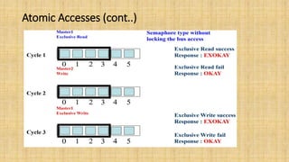
![Data read and write structure
• WSTRB : This signal indicates which byte lanes to update in memory.
There is one strobe for each eight bits of the write data bus.
• The WSTRB[n:0] signals when HIGH, specify the byte lanes of the data
bus that contain valid information. There is one write strobe for each
eight bits of the write data bus, therefore WSTRB[n] corresponds to
WDATA[(8n)+7:(8n)].
• Narrow transfers
• the burst has five transfers
• the starting address is 0
• each transfer is eight bits
• the transfers are on a 32-bit bus
• the burst type is INCR.](https://image.slidesharecdn.com/ambhaaxi-210807173656/85/Ambha-axi-28-320.jpg)

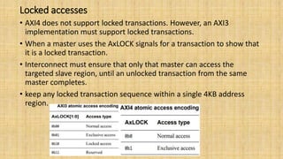
![Transaction attributes
• The AXI protocol defines ARCACHE and AWCACHE to support memory
and peripheral slaves.
AXI3 memory attribute signaling:
In AXI3, the AxCACHE[3:0] signals specify the Bufferable,
Cacheable, and Allocate attributes of the transaction. AxCACHE specify
ARCACHE&AWCACHE](https://image.slidesharecdn.com/ambhaaxi-210807173656/85/Ambha-axi-33-320.jpg)
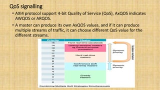
![Bufferable Bit
• Bufferable Bit(AxCACHE[0]): When this bit is asserted, The
interconnect or any component can delay the transaction for an
arbitrary number of cycles, usually only relevant to writes.
• IF a transaction is bufferable then It is acceptable for a bridge or system level
cache to provide write response.
• If non-bufferable then Final destination to provide response
Bufferable
Non Bufferable](https://image.slidesharecdn.com/ambhaaxi-210807173656/85/Ambha-axi-34-320.jpg)
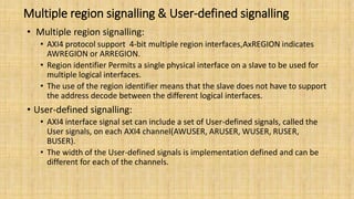
![Cache Support
• Cacheable Bit(AxCACHE[1]) :
Write : a number of different writes can be merged together
Read : a location can be pre-fetched or can be fetched just once
for multiple read transactions
• Read Allocate Bit(AxCACHE[2]):
If the transfer is a read and it misses in the cache, then it should
be allocated
• Write Allocate Bit(AxCACHE[3]):
If the transfer is a write and it misses in the cache, then it should
be allocated](https://image.slidesharecdn.com/ambhaaxi-210807173656/85/Ambha-axi-35-320.jpg)
![AXI4 changes to memory attribute signaling
• AXI4 makes the following changes to the AXI3 memory attribute
signaling:
• the AxCACHE[1] bits are renamed as the Modifiable bits
• ordering requirements are defined for Non-modifiable transactions
• the meanings of Read-allocate and Write-allocate are updated.
Non-modifiable transactions (AxCACHE[1] LOW)
A Non-modifiable transaction must not be split into multiple
transactions or merged with other transactions also below parameters
must not be changed.](https://image.slidesharecdn.com/ambhaaxi-210807173656/85/Ambha-axi-36-320.jpg)
![Modifiable transactions (AxCACHE[1] high)
• A Modifiable transaction can be modified in the following ways:
• a transaction can be broken into multiple transactions
• multiple transactions can be merged into a single transaction
• a read transaction can fetch more data than required
• a write transaction can access a larger address range than required, using the
WSTRB signals to ensure that only the appropriate locations are updated.
• AxLOCK, AxPROT must not be changed.
• in each generated transaction, the following signals can be modified:
• the transfer address, AxADDR
• the burst size, AxSIZE
• the burst length, AxLEN
• the burst type, AxBURST.](https://image.slidesharecdn.com/ambhaaxi-210807173656/85/Ambha-axi-37-320.jpg)
![Access permissions(Contd..)
• Data / Instruction: This bit gives an indication if the transaction is an
instruction or a data access.
• AxPROT[2] LOW to indicate a data access unless the access is
specifically known to be an instruction access.](https://image.slidesharecdn.com/ambhaaxi-210807173656/85/Ambha-axi-40-320.jpg)


The document provides an in-depth overview of the AMBA AXI protocol, emphasizing its key features, architecture, and transaction models, suitable for high-performance and low-latency system designs. It discusses separate channels for read/write operations, transaction ordering, and the protocol's compatibility with previous interfaces. Additionally, it covers extensions for low-power operation, transaction attributes, and the differences between AXI4 and AXI4-Lite specifications.