Download to read offline
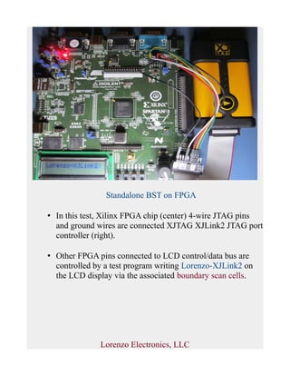

The document discusses enhancing an LE1201 automatic test equipment system to support an XJTAG XJLink2 JTAG controller. It presents results from standalone boundary scan tests of an FPGA using the XJLink2 controller to drive LCD pins and from testing a Microchip MPU development board, showing existing tests can be run without changes.


