Download to read offline
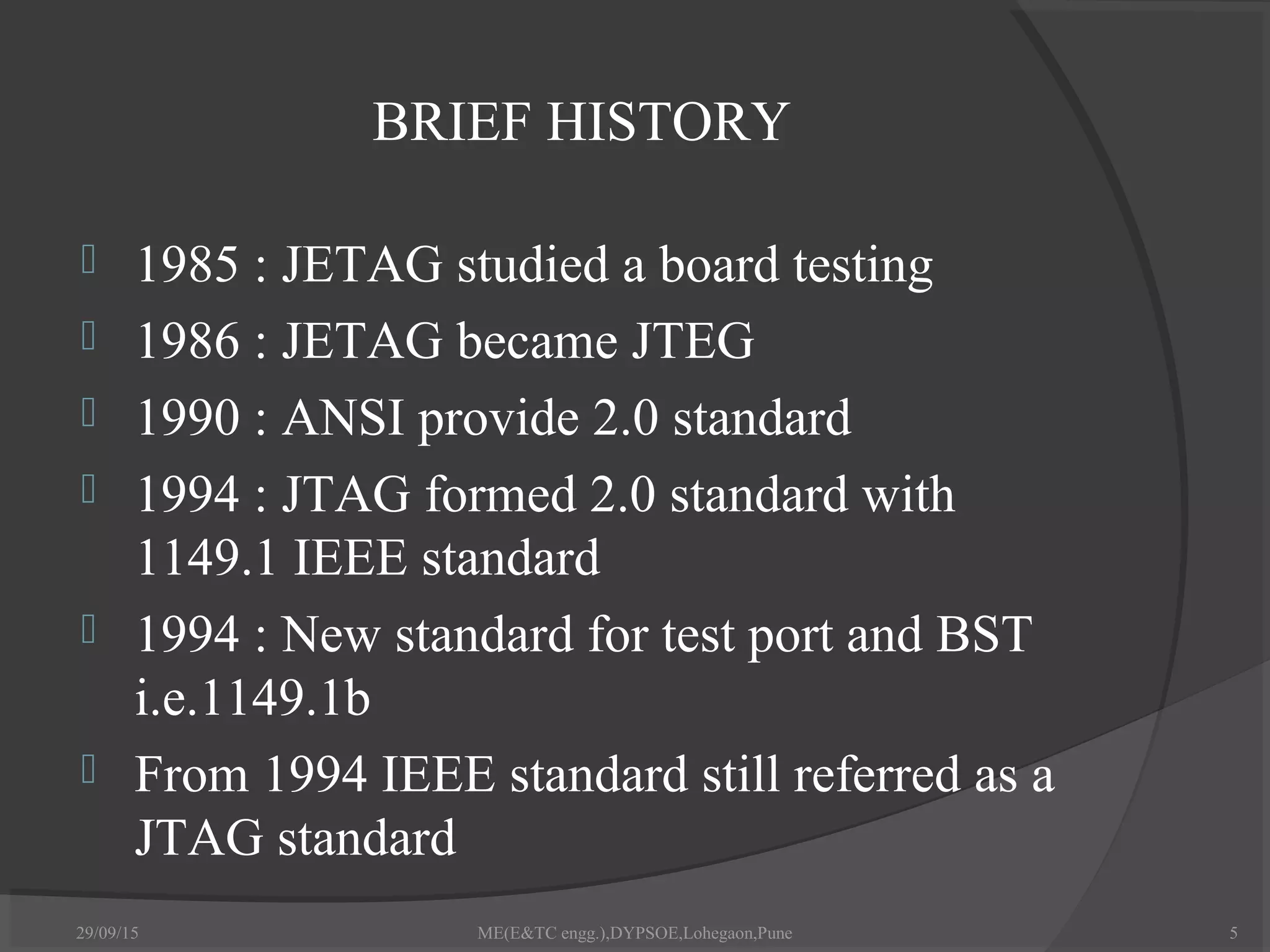
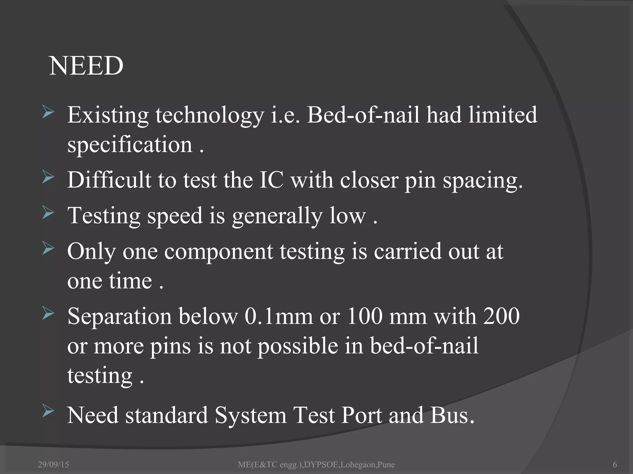
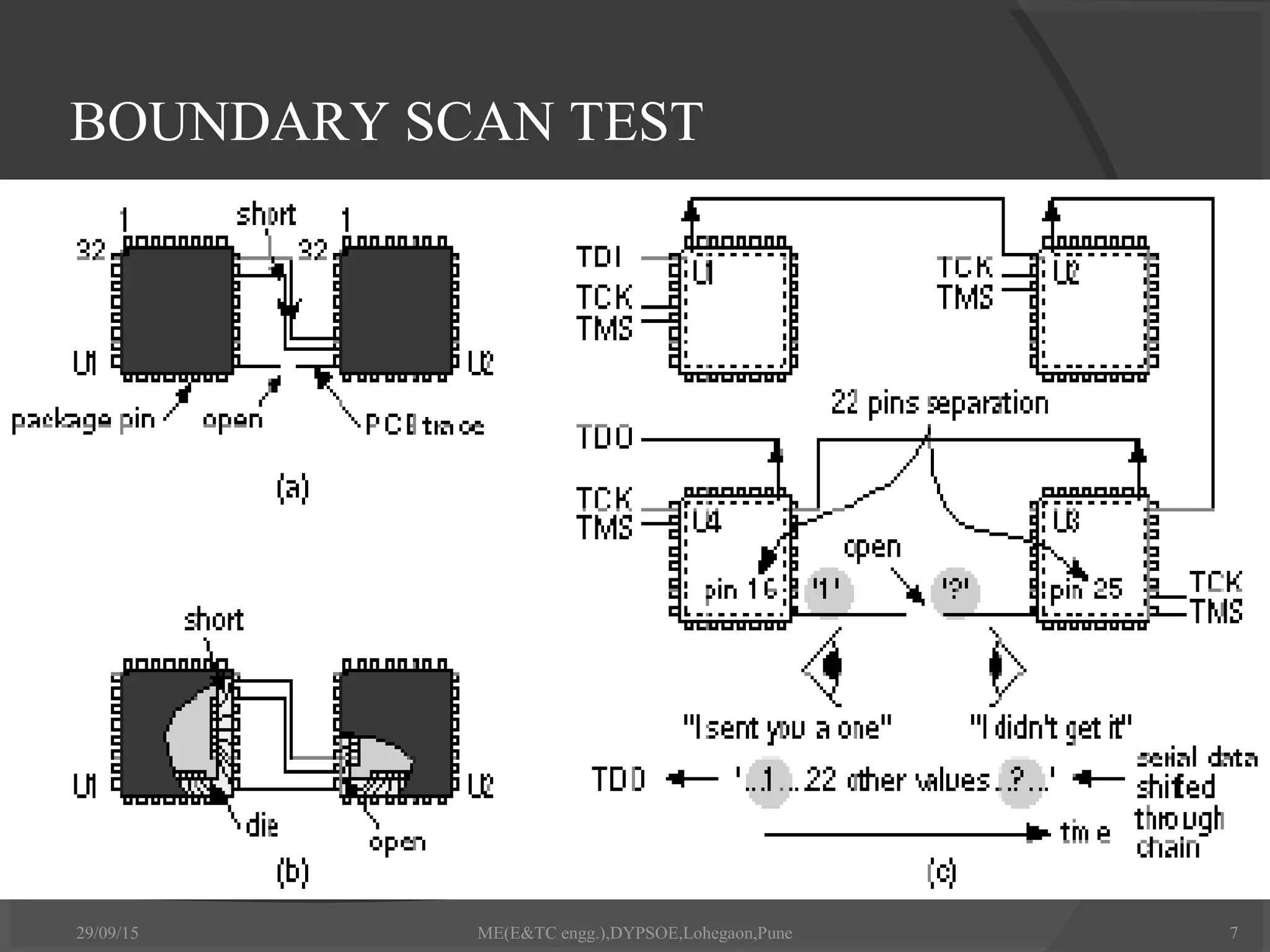

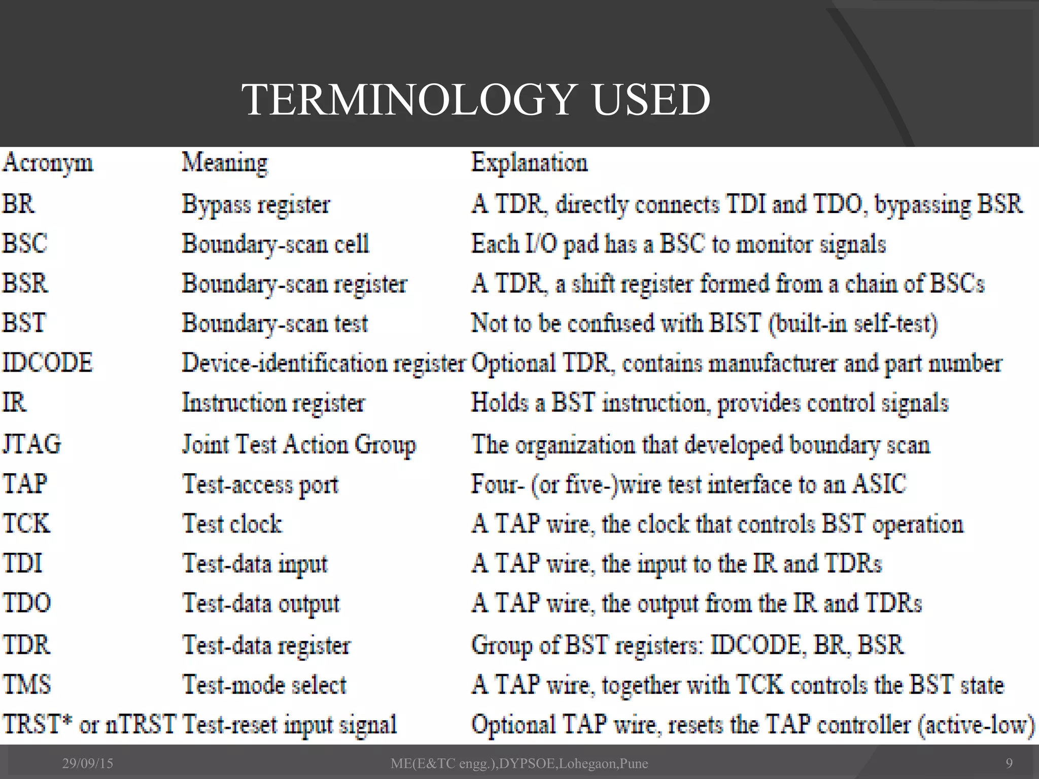
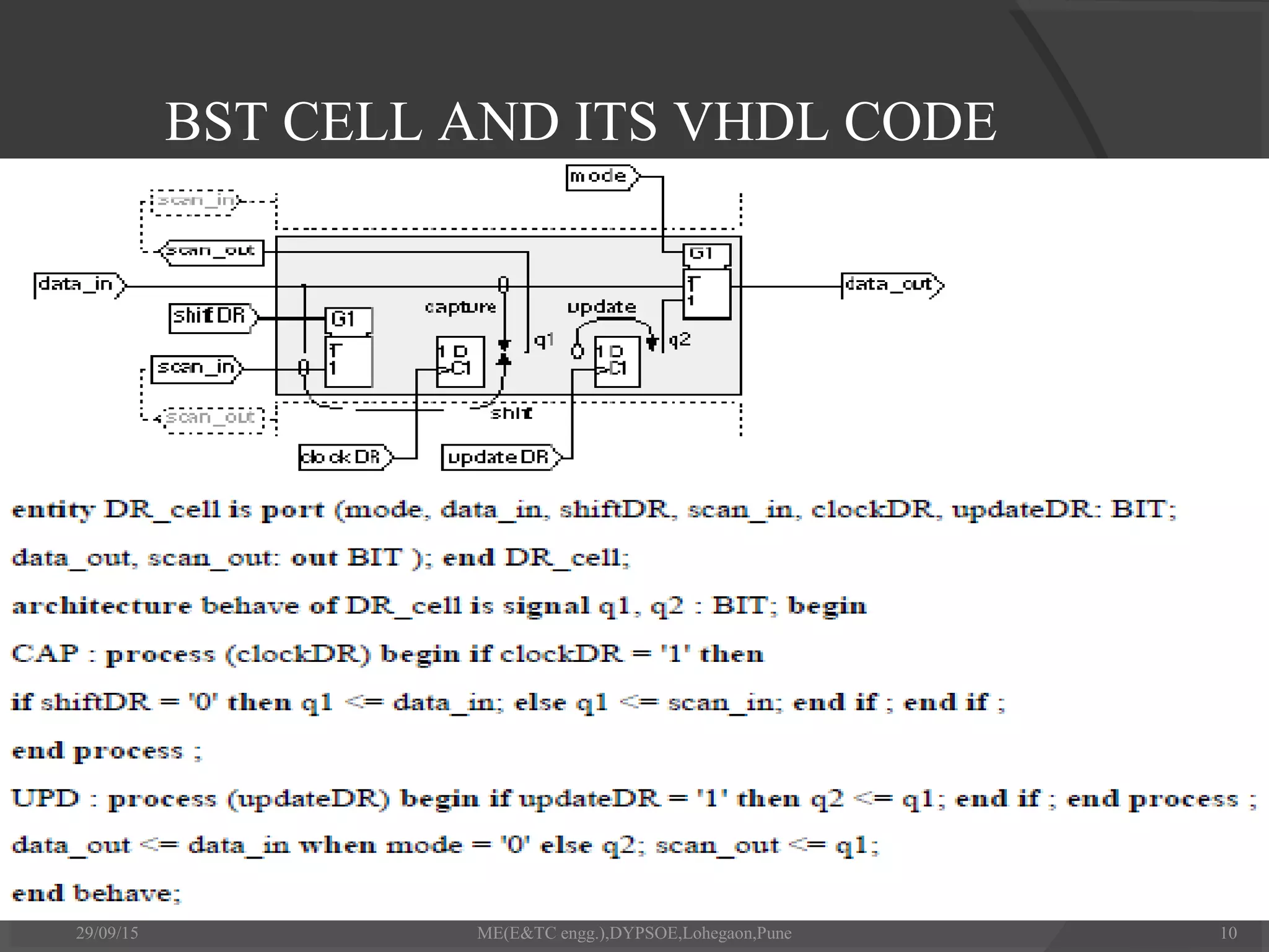
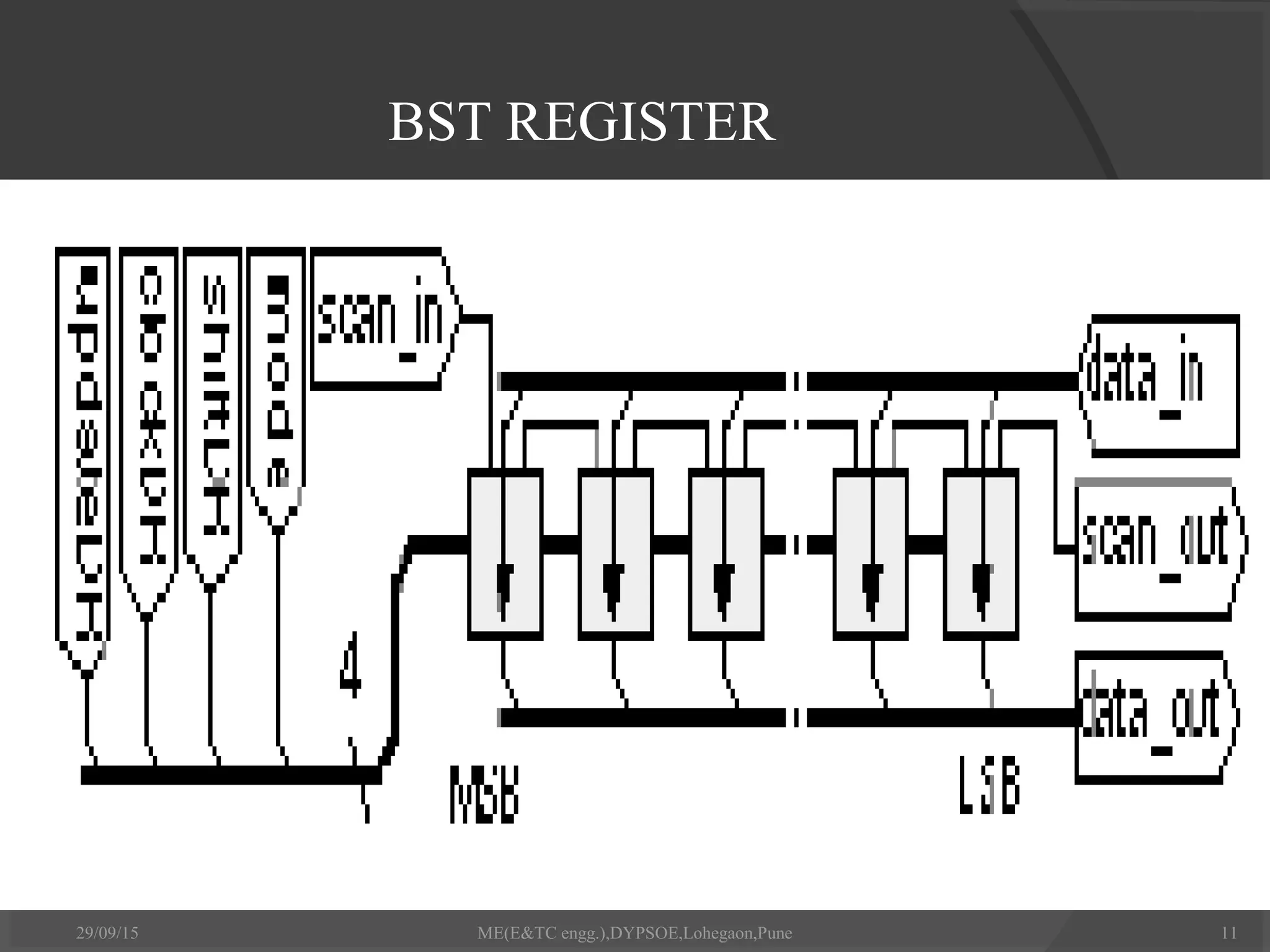
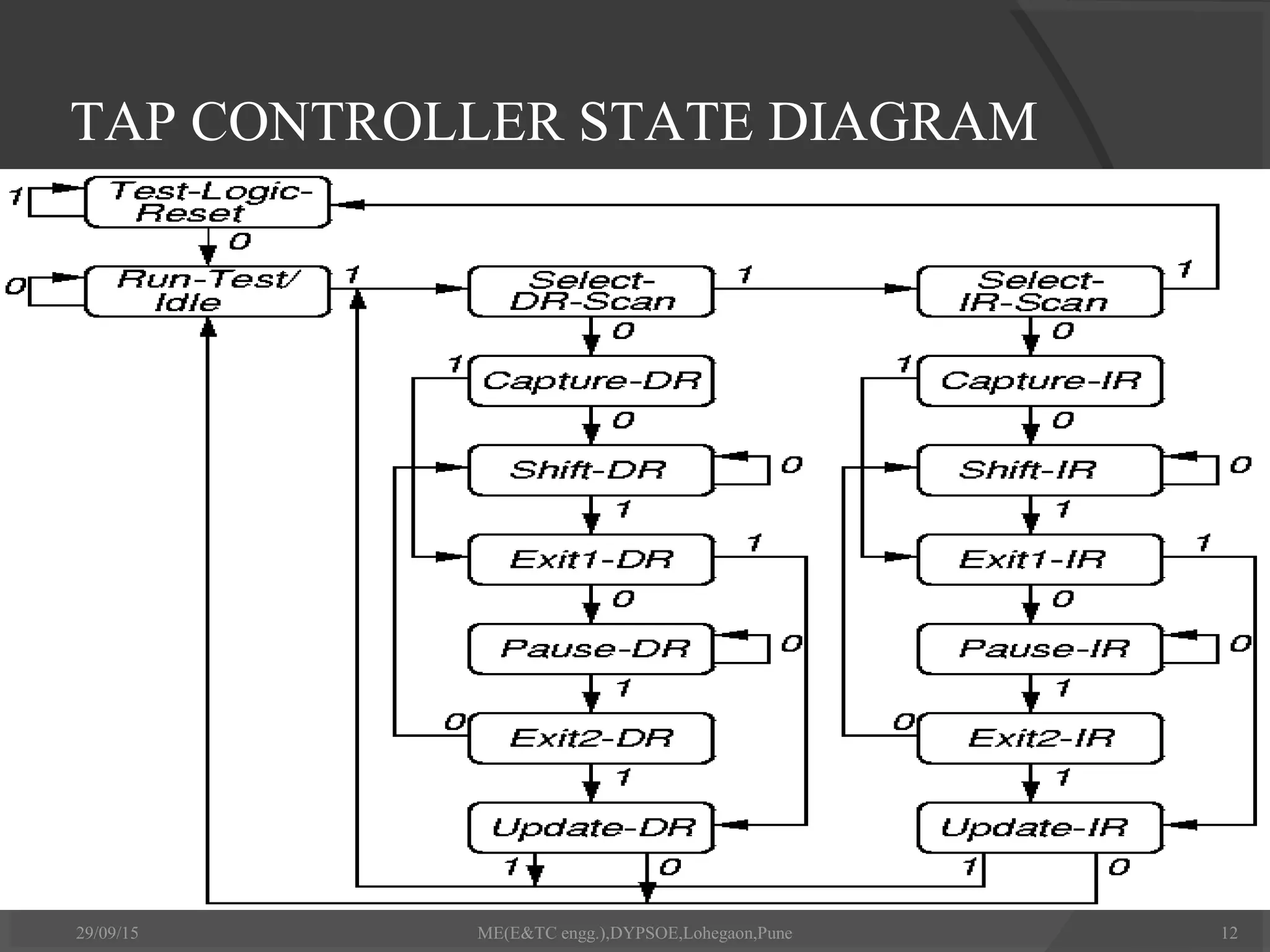
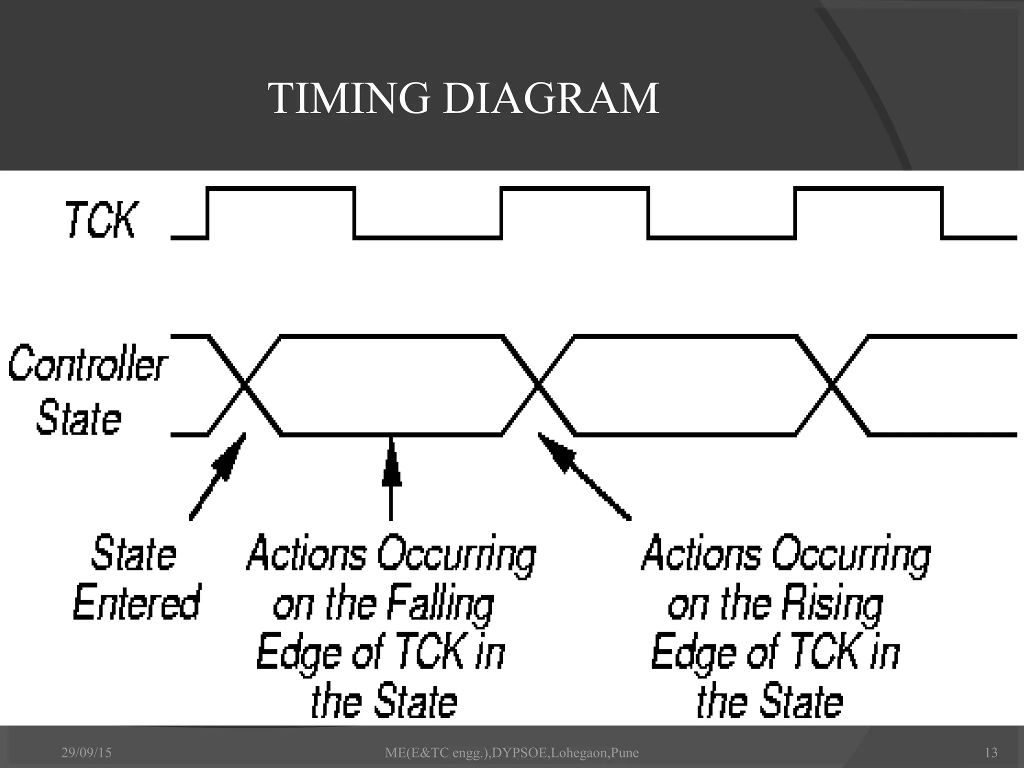
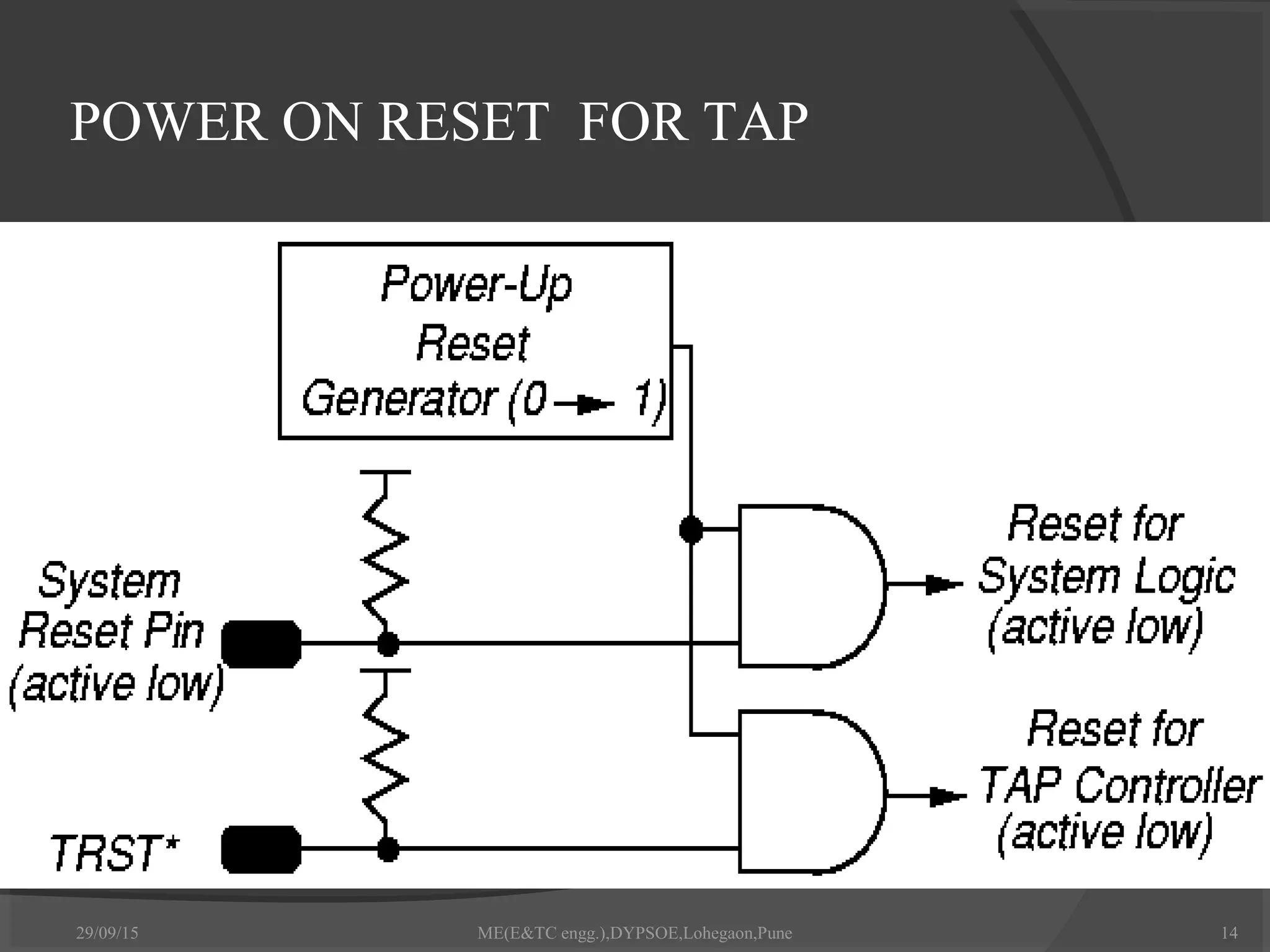
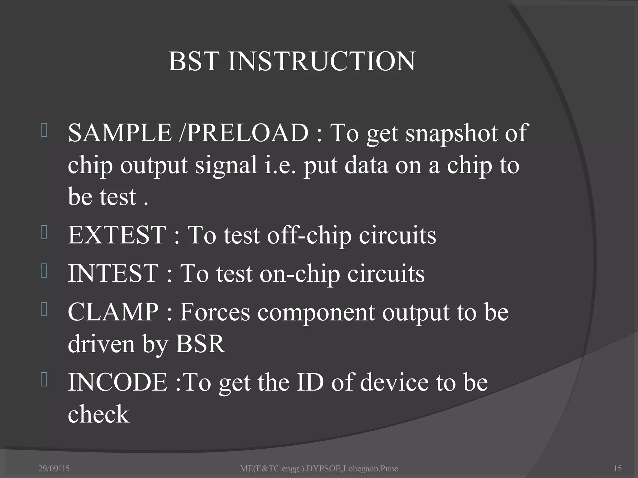
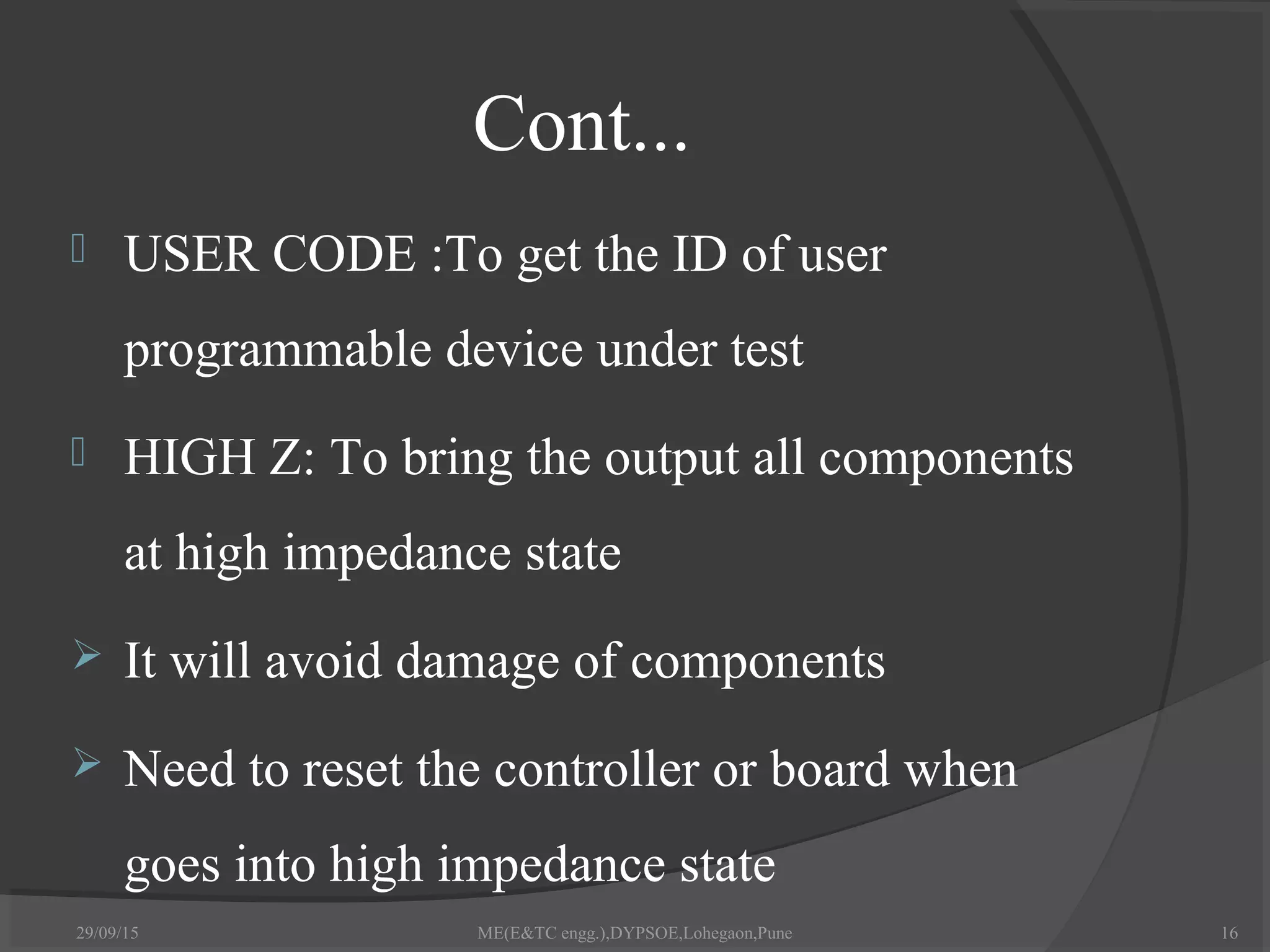


The document discusses boundary scan testing (BST), which is a method for testing boards, components, and ASICs. It provides an introduction to BST, outlines its history and need, describes four wire testing and key terminology. It also covers BST cells, registers, the TAP controller, instructions, and timing diagrams. It concludes that BST is an important tool for testing circuitry that cannot be tested with traditional bed-of-nails testers.


