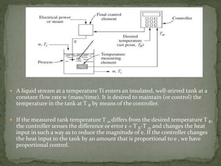
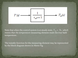
INSTRUMENTATION AND PROCESS CONTROL
 A control system is a device, or set of devices, that
manages, commands, directs or regulates the behavior
of other devices or systems.
 Industrial control systems are used in industrial
production for controlling equipment or machines.
• There are two common classes of control systems :-
• open loop control system.
• closed loop control systems.
 A liquid stream at a temperature Ti enters an insulated, well-stirred tank at a
constant flow rate w (mass/time). It is desired to maintain (or control) the
temperature in the tank at T R by means of the controller.
 If the measured tank temperature T m differs from the desired temperature T R,
the controller senses the difference or error ε = T R-T m and changes the heat
input in such a way as to reduce the magnitude of e. If the controller changes
the heat input to the tank by an amount that is proportional to e , we have
proportional control.
COMPONENTS OF THE CONTROL SYSTEM:
1) Process (stirred-tank heater).
2) Measuring element (thermometer).
3) Controller
4) Final control element (variable transformer or control
valve).
 The set point is a synonym for the desired value of the
controlled variable.
 The load refers to a change in any variable that may cause
the controlled variable of the process to change.
 The control system shown in Figure is called a closed-loop
system or a feedback system because the measured value of
the controlled variable is returned or “fed back” to a device
called the comparator.
 In the comparator, the controlled variable is compared with
the desired value or set point.
 If there is any difference between the measured variable and
the set point, an error is generated.
 This error enters a controller, which in turn adjusts the final
control element to return the controlled variable to the set
point.
 The feedback principle, which involves the use of the controlled variable
T to maintain itself at a desired value T R .
 Negative feedback ensures that the difference between T R and T m is
used to adjust the control element so that the tendency is to reduce the
error.
 For example : assume that the system is at steady state and that T T m T
R . If the load T i should increase, T and T m would start to increase,
which would cause the error e to become negative.
 With proportional control, the decrease in error would cause the
controller and final control element to decrease the flow of heat to the
system, with the result that the flow of heat would eventually be reduced
to a value such that T approaches T R .
 If the signal to the comparator were obtained by adding T R
and T m , we would have a positive feedback system.
 assume that the system is at steady state and that Tm T R .
If Ti were to increase, T and T m would increase, which
would cause the signal from the comparator to increase,
with the result that the heat to the system would increase.
 In the first situation, which is called the servomechanism-type (or
servo) problem, we assume that there is no change in load Ti and
that we are interested in changing the bath temperature according
to some prescribed function of time.
 For this problem, the set point T R would be changed in accordance
with the desired variation in bath temperature.
 If the variation is sufficiently slow, the bath temperature may be
expected to follow the variation in T R very closely.
 EXAMPLES : The tracking of missiles and aircraft and the
automatic machining of intricate parts from a master pattern
 The other situation will be referred to as THE
REGULATOR PROBLEM.
 In this case, the desired value T R is to remain fixed,
and the purpose of the control system is to maintain
the controlled variable at T R in spite of changes in load
Ti.
 This problem is very common in the chemical
industry.
Consider first the block for the process.
An unsteady-state energy balance around the tank
gives,
Where T0 is the reference temperature
At steady state, dT/dt is zero, and Above Eq. can be written
where the subscript s has been used to indicate
steady state.
Subtracting above equations gives,
If we introduce the deviation variables,
Ti
’ = Ti – Tis
Q = q – qs
T’ = T – Ts
so,
Now, Taking the Laplace transform
This last expression can be written
Where,
The gain for Q ( t ) is
The temperature measuring element, which senses the bath
temperature T and transmits a signal T m to the controller, may
exhibit some dynamic lag.
 In this example, we will assume that the temperature measuring
element is a first-order system, for which the transfer function is
MEASURING ELEMENT TRANSFER FUNCTION
where the input-output variables T’ and T’m are deviation variables,
defined as
T’ = T – Ts
Tm
’ = Tm - Tms
Note that when the control system is at steady state, Tms = Ts , which
means that the temperature measuring element reads the true bath
temperature.
The transfer function for the measuring element may be represented
by the block diagram shown in Above Fig.
It is assumed that the controller is a proportional controller.
The relationship for a proportional controller is
Where
TR = set- point temperature
Kc= Proportional sensitivity or
controller gain
A= Heat input when e =0
 At steady state, it is assumed that the set point, the process temperature,
and the measured temperature are all equal to one another; thus
TRs = Ts - Tms
 Let e’ be the deviation variable for error; thus
e' = e - es
where es = TRs - Tms.
 Since TRs = Tms, es = 0
e' = e - 0 = e
 This result shows that e is itself a deviation variable.
 Since at steady state there is no error, and A is the heat input for zero
error,
 So a proportional controller equation an be written as
Or
Where, Q = q-qs
The transform of above function gives
Note that e , which is also equal to e’ , may be expressed as
 Process System Analysis & Control - Coughanower and Kappel, Mc-Graw
Hill Book Company.
 https://en.wikipedia.org/wiki/Control_system
 web.iku.edu.tr/courses/ee/ee670/ee670/lecture%20notes/ch01.pdf
THE CONTROL SYSTEM

THE CONTROL SYSTEM

  • 1.
  • 2.
     A controlsystem is a device, or set of devices, that manages, commands, directs or regulates the behavior of other devices or systems.  Industrial control systems are used in industrial production for controlling equipment or machines. • There are two common classes of control systems :- • open loop control system. • closed loop control systems.
  • 3.
     A liquidstream at a temperature Ti enters an insulated, well-stirred tank at a constant flow rate w (mass/time). It is desired to maintain (or control) the temperature in the tank at T R by means of the controller.  If the measured tank temperature T m differs from the desired temperature T R, the controller senses the difference or error ε = T R-T m and changes the heat input in such a way as to reduce the magnitude of e. If the controller changes the heat input to the tank by an amount that is proportional to e , we have proportional control.
  • 4.
    COMPONENTS OF THECONTROL SYSTEM: 1) Process (stirred-tank heater). 2) Measuring element (thermometer). 3) Controller 4) Final control element (variable transformer or control valve).
  • 5.
     The setpoint is a synonym for the desired value of the controlled variable.  The load refers to a change in any variable that may cause the controlled variable of the process to change.
  • 6.
     The controlsystem shown in Figure is called a closed-loop system or a feedback system because the measured value of the controlled variable is returned or “fed back” to a device called the comparator.  In the comparator, the controlled variable is compared with the desired value or set point.  If there is any difference between the measured variable and the set point, an error is generated.  This error enters a controller, which in turn adjusts the final control element to return the controlled variable to the set point.
  • 7.
     The feedbackprinciple, which involves the use of the controlled variable T to maintain itself at a desired value T R .  Negative feedback ensures that the difference between T R and T m is used to adjust the control element so that the tendency is to reduce the error.  For example : assume that the system is at steady state and that T T m T R . If the load T i should increase, T and T m would start to increase, which would cause the error e to become negative.  With proportional control, the decrease in error would cause the controller and final control element to decrease the flow of heat to the system, with the result that the flow of heat would eventually be reduced to a value such that T approaches T R .
  • 8.
     If thesignal to the comparator were obtained by adding T R and T m , we would have a positive feedback system.  assume that the system is at steady state and that Tm T R . If Ti were to increase, T and T m would increase, which would cause the signal from the comparator to increase, with the result that the heat to the system would increase.
  • 9.
     In thefirst situation, which is called the servomechanism-type (or servo) problem, we assume that there is no change in load Ti and that we are interested in changing the bath temperature according to some prescribed function of time.  For this problem, the set point T R would be changed in accordance with the desired variation in bath temperature.  If the variation is sufficiently slow, the bath temperature may be expected to follow the variation in T R very closely.  EXAMPLES : The tracking of missiles and aircraft and the automatic machining of intricate parts from a master pattern
  • 10.
     The othersituation will be referred to as THE REGULATOR PROBLEM.  In this case, the desired value T R is to remain fixed, and the purpose of the control system is to maintain the controlled variable at T R in spite of changes in load Ti.  This problem is very common in the chemical industry.
  • 11.
    Consider first theblock for the process. An unsteady-state energy balance around the tank gives, Where T0 is the reference temperature At steady state, dT/dt is zero, and Above Eq. can be written where the subscript s has been used to indicate steady state.
  • 12.
    Subtracting above equationsgives, If we introduce the deviation variables, Ti ’ = Ti – Tis Q = q – qs T’ = T – Ts so, Now, Taking the Laplace transform
  • 13.
    This last expressioncan be written Where, The gain for Q ( t ) is
  • 14.
    The temperature measuringelement, which senses the bath temperature T and transmits a signal T m to the controller, may exhibit some dynamic lag.  In this example, we will assume that the temperature measuring element is a first-order system, for which the transfer function is MEASURING ELEMENT TRANSFER FUNCTION where the input-output variables T’ and T’m are deviation variables, defined as T’ = T – Ts Tm ’ = Tm - Tms
  • 15.
    Note that whenthe control system is at steady state, Tms = Ts , which means that the temperature measuring element reads the true bath temperature. The transfer function for the measuring element may be represented by the block diagram shown in Above Fig.
  • 16.
    It is assumedthat the controller is a proportional controller. The relationship for a proportional controller is Where TR = set- point temperature Kc= Proportional sensitivity or controller gain A= Heat input when e =0
  • 17.
     At steadystate, it is assumed that the set point, the process temperature, and the measured temperature are all equal to one another; thus TRs = Ts - Tms  Let e’ be the deviation variable for error; thus e' = e - es where es = TRs - Tms.  Since TRs = Tms, es = 0 e' = e - 0 = e  This result shows that e is itself a deviation variable.  Since at steady state there is no error, and A is the heat input for zero error,
  • 18.
     So aproportional controller equation an be written as Or Where, Q = q-qs The transform of above function gives Note that e , which is also equal to e’ , may be expressed as
  • 19.
     Process SystemAnalysis & Control - Coughanower and Kappel, Mc-Graw Hill Book Company.  https://en.wikipedia.org/wiki/Control_system  web.iku.edu.tr/courses/ee/ee670/ee670/lecture%20notes/ch01.pdf