Course Objectives
This Coursewill enable students to:
• Gain knowledge of developing basic skills
necessary for importance Process controller (Digital
and Analog Controller) Used in Various Industry.
• Understand the concepts and various Operation
using Automation Process System by using various
Process Control System.
• Determine and Diagnose the Principles of Various
Digital and Analog Controller and ADC, DAC.
3.
Course Syllabus
Module-1
INTRODUCTION TOPROCESS CONTROL: Process control block diagram, control system
evaluation. Final control: introduction to final control operation, signal conversions, actuators,
control elements. Alarm and annunciators, control drawing: P & ID symbols and diagrams, flow
sheet symbols, inter logic symbols, graphic symbols.
Module-2
Introduction, process characteristics, control system parameters, discontinuous control modes,
continuous control modes, and composite control modes
Module-3
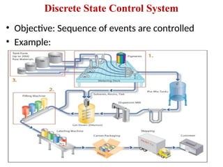
DISCRETE-STATE PROCESS CONTROL: Introduction, definition and characteristics of discrete
state process control. Control-loop characteristics: Introduction, control system configuration,
multivariable control systems, control system quality, stability, and process loop tuning.
Module-4
ANALOG CONTROLLERS: Introduction, general features, electronic controllers, pneumatic
controllers, designs considerations.
Module-5
DIGITAL–TO-ANALOG CONVERTERS: V-F, and F-V converters, performance specifications,
D-A conversion techniques (R-2R & binary weighted) multiplying DAC applications. A-D
conversion techniques (flash, successive approximation, single slope, dual slope), over sampling
converters.
4.
Text Books
Prescribed TextBook:
• Process Control Instrumentation Technology-C
D Johnson
Reference Books:
• Design with operational amplifiers and analog
integrated circuits-3rd Edition, SERGIO
FRANCO, Tata McGraw Hill.
5.
Course Outcomes (CO):
•CO1. Discuss the basic block diagram of Process Control used
in various industries, have a knowledge of Final Control
operation and to study different Piping and Instrumentation
symbols.[KL2]
• CO2. Describe the Characteristics and parameters of process
control and discuss various control modes [KL3]
• CO3. Analyze Discrete State Process control and to analyze
its characteristics[KL3]
• CO4. Analyze Analog Controllers such as electronic
controllers, pneumatic controllers and also analyze the designs
considerations [KL3]
• CO5.Discuss and Analyze Digital to Analog Converters and
analog to digital converters and evaluate the performance
specifications [KL4]
6.
Introduction
• The termcontrol means methods to force
parameters in the environment to some specific
values.
Ex: This can be as simple as making the temperature
in a room stay at 21 degree Celsius or as complex as
manufacturing an integrated circuit or guiding a
spacecraft to Jupiter.
• In general, all the elements necessary to accomplish
the control objective are described by the term
control system
Control Systems
• Whatis control system
• Natural Example of Control system
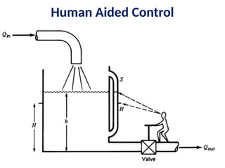
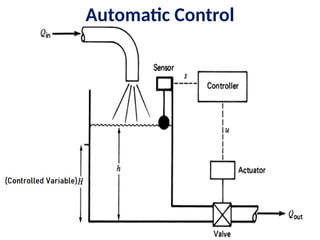
• Control system is sub divided into
1. Process Control Principles (Human Aided Control,
Automatic Control),
2.Servomechanisms
3. Discrete state Control Systems
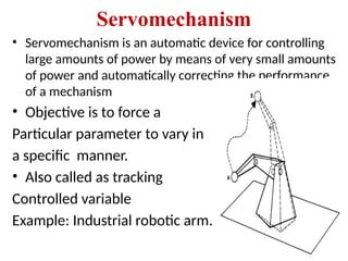
Servomechanism
• Servomechanism isan automatic device for controlling
large amounts of power by means of very small amounts
of power and automatically correcting the performance
of a mechanism
• Objective is to force a
Particular parameter to vary in
a specific manner.
• Also called as tracking
Controlled variable
Example: Industrial robotic arm.
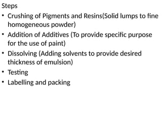
Steps
• Crushing ofPigments and Resins(Solid lumps to fine
homogeneous powder)
• Addition of Additives (To provide specific purpose
for the use of paint)
• Dissolving (Adding solvents to provide desired
thickness of emulsion)
• Testing
• Labelling and packing
16.
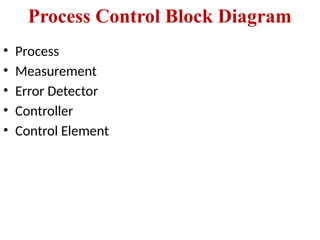
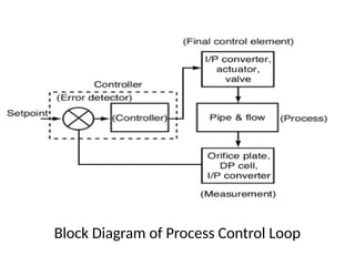
Process Control BlockDiagram
• Process
• Measurement
• Error Detector
• Controller
• Control Element
17.
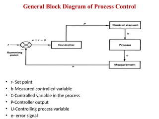
General Block Diagramof Process Control
• r- Set point
• b-Measured controlled variable
• C-Controlled variable in the process
• P-Controller output
• U-Controlling process variable
• e- error signal
18.
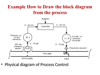
Example How toDraw the block diagram
from the process
• Physical diagram of Process Control
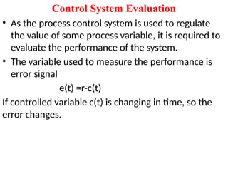
Control System Evaluation
•As the process control system is used to regulate
the value of some process variable, it is required to
evaluate the performance of the system.
• The variable used to measure the performance is
error signal
e(t) =r-c(t)
If controlled variable c(t) is changing in time, so the
error changes.
21.
Control system objective
•The system should be stable
• The system should provide the best possible steady
state regulation
• The system should provide the best possible
transient response
22.
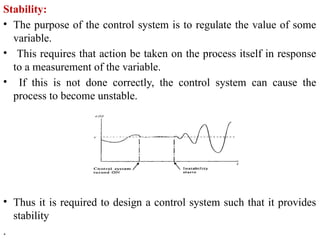
Stability:
• The purposeof the control system is to regulate the value of some
variable.
• This requires that action be taken on the process itself in response
to a measurement of the variable.
• If this is not done correctly, the control system can cause the
process to become unstable.
• Thus it is required to design a control system such that it provides
stability
.
23.
Steady-State Regulation
• objectiveof the best possible steady-state regulation simply
means that the “steady state” error should be a minimum.
• Generally, when a control system is specified, there will be
some allowable deviation, +/- Δc, about the setpoint.
• This means that variations of the variable within this band are
expected and acceptable.
• External influences that tend to cause drifts of the value
beyond the allowable deviation are corrected by the control
system.
• For example, a process-control technologist might be asked to
design and implement a control system to regulate
temperature at 150 degree Celsius within +/-2 degree Celsius .
This means the setpoint is to be 150 degree Celsius , but the
temperature may be allowed to vary within the range of 148
degree Celsius to 152 degree Celsius .
24.
Transient Regulation
• Weneed to analyse what happens to the value of controlled
variable when some sudden transient event occurs
• Ex: if the set point is changed from 150 to 160 degree
Celsius.
• Thus the transient regulation specifies how the control
system reacts to bring the temperature to this new set point
• Another type of transient influence is a sudden change of
some other process variable on which the controlled
variable is depending.
• Therefore if any of the variable changes then how the
controlled variable may be driven to change, so that the
control system acts to minimize the effect. This is known as
transient response.
25.
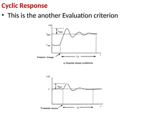
Evaluation Criterion
• Manycriterions are available for gauging the
response.
• Tuning is used to indicate how a process control
loop is adjusted to provide the best control
1. Damped Response
• It is a type of criterion required so that the
controlled variable exhibits its response as shown
for both set point change and transient effects.
27.
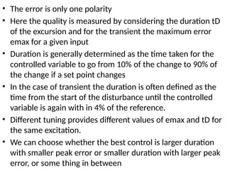
• The erroris only one polarity
• Here the quality is measured by considering the duration tD
of the excursion and for the transient the maximum error
emax for a given input
• Duration is generally determined as the time taken for the
controlled variable to go from 10% of the change to 90% of
the change if a set point changes
• In the case of transient the duration is often defined as the
time from the start of the disturbance until the controlled
variable is again with in 4% of the reference.
• Different tuning provides different values of emax and tD for
the same excitation.
• We can choose whether the best control is larger duration
with smaller peak error or smaller duration with larger peak
error, or some thing in between
• Here thecontrolled variable oscillates about the set
point
• Parameters considered are emax and tD(settling
time)
• tD is obtained by measuring the time when the
allowable error is first exceeded to the time when it
falls within the allowable error and stays.
• Thus nature of the response can be modified by
adjusting the control loop parameters, which is
called tuning.
• We can consider large maximum error but short
duration or small maximum error but large duration
or any thing in between.
30.
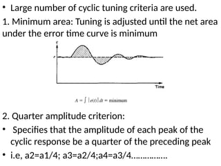
• Large numberof cyclic tuning criteria are used.
1. Minimum area: Tuning is adjusted until the net area
under the error time curve is minimum
2. Quarter amplitude criterion:
• Specifies that the amplitude of each peak of the
cyclic response be a quarter of the preceding peak
• i.e, a2=a1/4; a3=a2/4;a4=a3/4…………….
31.
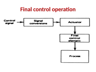
Introduction to finalcontrol element
• Importance process control aplicaiton
• Function of final control element
• Selection of final control element after
detailed process
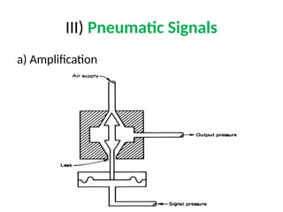
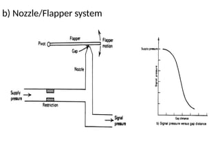
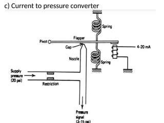
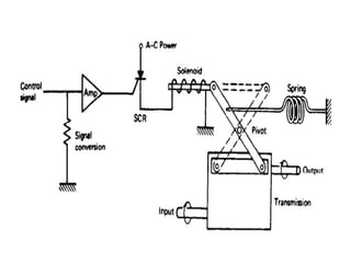
Signal Conversion
• Whysignal conversion
• Example
• Objective of signal conversion
• General controller output signals
1. Electric current
2. Pneumatic pressure
3. Digital signals
2. Amplifiers
• Highpower ac or dc amplifiers can provide
conversion of low energy signals to high energy
signals
• These amplifiers may serve the purpose of
Motor control
Heat control
light control
3.Motor control:
Many motor control circuits are designed as a
packaged units that accepts low level ac signal
directly to control motor speed
36.
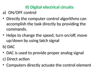
II) Digital electricalcircuits
a) ON/OFF control
• Directly the computer control algorithms can
accomplish the task directly by providing the
commands.
• Helps to change the speed, turn on/off, move
up/down by using latch signal
b) DAC
• DAC is used to provide proper analog signal
c) Direct action
• Computers directly actuate the control element
Actuators
• The signalconvertors provide an amplified or
converted signals that helps to actuate the
mechanism that changes a controlling variable in
the process.
• Examples: 1. Valve 2. Heater etc
• Goal:
The goal of the actuator is to translate the control
signal into action on the control element
Ex. Converting the control signal into the physical
action of opening or closing the valve
41.
• Types ofactuators
1. Electrical actuators
2. Pneumatic actuators
3. Hydraulic actuators
1.Electrical Actuators:
• An electric actuator is a mechanical device used to
convert electricity into kinetic energy in either a
single linear or rotary motion.
• Ex. Solenoids, Electrical motors such as dc motor, ac
motor, stepper motor
42.
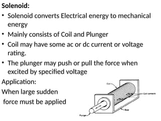
Solenoid:
• Solenoid convertsElectrical energy to mechanical
energy
• Mainly consists of Coil and Plunger
• Coil may have some ac or dc current or voltage
rating.
• The plunger may push or pull the force when
excited by specified voltage
Application:
When large sudden
force must be applied
45.
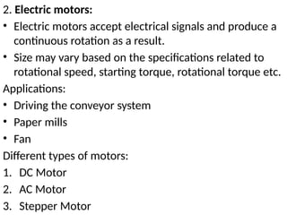
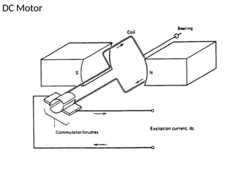
2. Electric motors:
•Electric motors accept electrical signals and produce a
continuous rotation as a result.
• Size may vary based on the specifications related to
rotational speed, starting torque, rotational torque etc.
Applications:
• Driving the conveyor system
• Paper mills
• Fan
Different types of motors:
1. DC Motor
2. AC Motor
3. Stepper Motor
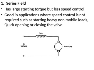
1. Series Field
•Has large starting torque but less speed control
• Good in applications where speed control is not
required such as starting heavy non mobile loads,
Quick opening or closing the valve
48.
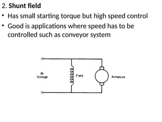
2. Shunt field
•Has small starting torque but high speed control
• Good is applications where speed has to be
controlled such as conveyor system
49.
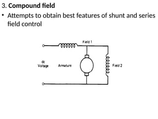
3. Compound field
•Attempts to obtain best features of shunt and series
field control
50.
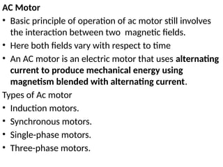
AC Motor
• Basicprinciple of operation of ac motor still involves
the interaction between two magnetic fields.
• Here both fields vary with respect to time
• An AC motor is an electric motor that uses alternating
current to produce mechanical energy using
magnetism blended with alternating current.
Types of Ac motor
• Induction motors.
• Synchronous motors.
• Single-phase motors.
• Three-phase motors.
51.
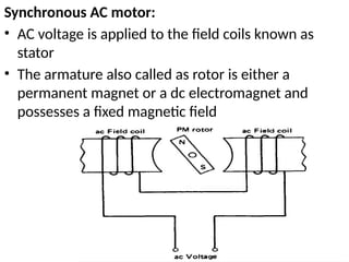
Synchronous AC motor:
•AC voltage is applied to the field coils known as
stator
• The armature also called as rotor is either a
permanent magnet or a dc electromagnet and
possesses a fixed magnetic field
52.
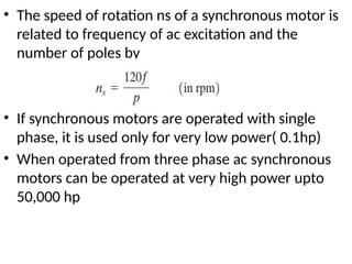
• The speedof rotation ns of a synchronous motor is
related to frequency of ac excitation and the
number of poles by
• If synchronous motors are operated with single
phase, it is used only for very low power( 0.1hp)
• When operated from three phase ac synchronous
motors can be operated at very high power upto
50,000 hp
53.
Induction motor:
• Inductionmotor rotor is neither a PM or dc excited
electro magnet, instead current induced in a coil
wound on the rotor generates the interacting
magnetic field of the rotor.
• This current is induced from the stator coil
• According to faradays law the changing flux will
induce current in the loop,
this in turn creates a
magnetic field in the rotor
coil which interacts with the
field of the stator.
54.
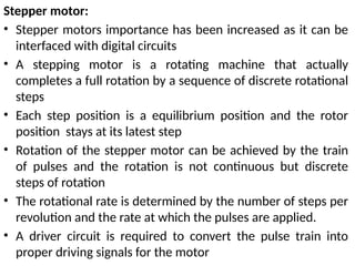
Stepper motor:
• Steppermotors importance has been increased as it can be
interfaced with digital circuits
• A stepping motor is a rotating machine that actually
completes a full rotation by a sequence of discrete rotational
steps
• Each step position is a equilibrium position and the rotor
position stays at its latest step
• Rotation of the stepper motor can be achieved by the train
of pulses and the rotation is not continuous but discrete
steps of rotation
• The rotational rate is determined by the number of steps per
revolution and the rate at which the pulses are applied.
• A driver circuit is required to convert the pulse train into
proper driving signals for the motor
56.
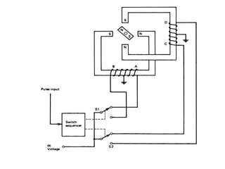
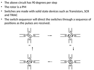
• The abovecircuit has 90 degrees per step
• The rotor is a PM
• Switches are made with solid state devices such as Transistors, SCR
and TRIAC
• The switch sequencer will direct the switches through a sequence of
positions as the pulses are received.
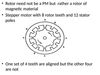
57.
• Rotor neednot be a PM but rather a rotor of
magnetic material
• Stepper motor with 8 rotor teeth and 12 stator
poles
• One set of 4 teeth are aligned but the other four
are not
58.
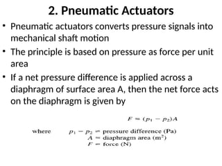
2. Pneumatic Actuators
•Pneumatic actuators converts pressure signals into
mechanical shaft motion
• The principle is based on pressure as force per unit
area
• If a net pressure difference is applied across a
diaphragm of surface area A, then the net force acts
on the diaphragm is given by
59.
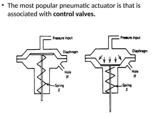
• The mostpopular pneumatic actuator is that is
associated with control valves.
61.
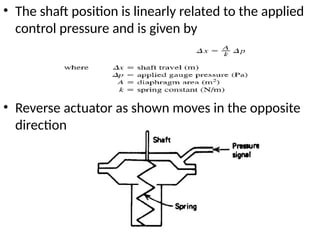
• The shaftposition is linearly related to the applied
control pressure and is given by
• Reverse actuator as shown moves in the opposite
direction
62.
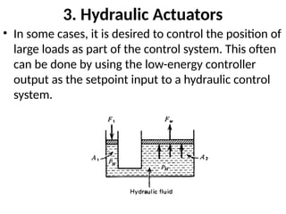
3. Hydraulic Actuators
•In some cases, it is desired to control the position of
large loads as part of the control system. This often
can be done by using the low-energy controller
output as the setpoint input to a hydraulic control
system.
64.
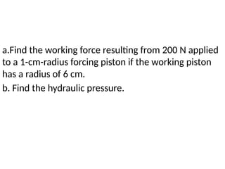
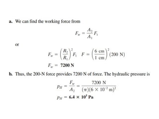
a.Find the workingforce resulting from 200 N applied
to a 1-cm-radius forcing piston if the working piston
has a radius of 6 cm.
b. Find the hydraulic pressure.
66.
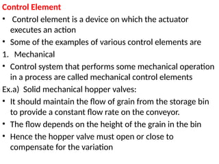
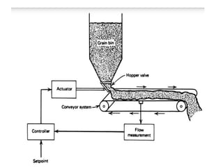
Control Element
• Controlelement is a device on which the actuator
executes an action
• Some of the examples of various control elements are
1. Mechanical
• Control system that performs some mechanical operation
in a process are called mechanical control elements
Ex.a) Solid mechanical hopper valves:
• It should maintain the flow of grain from the storage bin
to provide a constant flow rate on the conveyor.
• The flow depends on the height of the grain in the bin
• Hence the hopper valve must open or close to
compensate for the variation
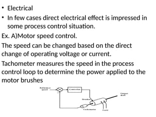
• Electrical
• Infew cases direct electrical effect is impressed in
some process control situation.
Ex. A)Motor speed control.
The speed can be changed based on the direct
change of operating voltage or current.
Tachometer measures the speed in the process
control loop to determine the power applied to the
motor brushes
70.
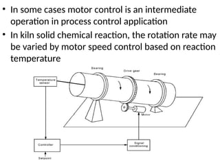
• In somecases motor control is an intermediate
operation in process control application
• In kiln solid chemical reaction, the rotation rate may
be varied by motor speed control based on reaction
temperature
71.
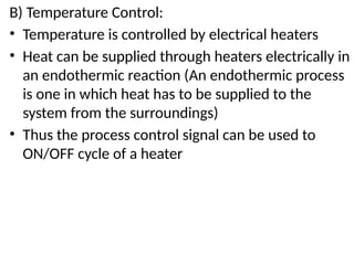
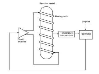
B) Temperature Control:
•Temperature is controlled by electrical heaters
• Heat can be supplied through heaters electrically in
an endothermic reaction (An endothermic process
is one in which heat has to be supplied to the
system from the surroundings)
• Thus the process control signal can be used to
ON/OFF cycle of a heater
73.
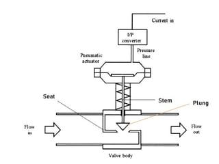
Fluid Valves
• Thechemical and petroleum industries have many
applications that require control of fluid processes.
• Many other industries also depend in part on
operations that involve fluids and the regulation of
fluid parameters.
• The word fluid here represents either gases,
liquids, or vapors.
• The different types of control valves are classified
by a relationship between the valve stem position
and the flow rate through the valve
75.
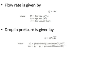
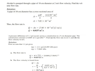
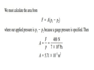
• Flow rateis given by
• Drop in pressure is given by
77.
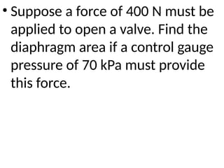
• Suppose aforce of 400 N must be
applied to open a valve. Find the
diaphragm area if a control gauge
pressure of 70 kPa must provide
this force.
79.
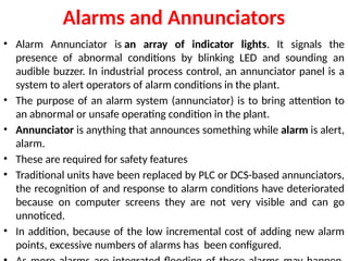
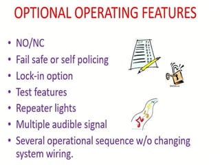
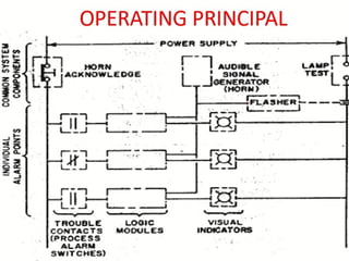
Alarms and Annunciators
•Alarm Annunciator is an array of indicator lights. It signals the
presence of abnormal conditions by blinking LED and sounding an
audible buzzer. In industrial process control, an annunciator panel is a
system to alert operators of alarm conditions in the plant.
• The purpose of an alarm system (annunciator) is to bring attention to
an abnormal or unsafe operating condition in the plant.
• Annunciator is anything that announces something while alarm is alert,
alarm.
• These are required for safety features
• Traditional units have been replaced by PLC or DCS-based annunciators,
the recognition of and response to alarm conditions have deteriorated
because on computer screens they are not very visible and can go
unnoticed.
• In addition, because of the low incremental cost of adding new alarm
points, excessive numbers of alarms has been configured.
80.
• Conventional annunciatorscan be interfaced as front-end devices to
Distributed control systems(A distributed control system (DCS) is a
computerized control system for a process or plant usually with many
control loops, in which autonomous controllers are distributed
throughout the system, but there is no central operator supervisory
control.) through various communication links such as MODBUS
protocol using object linking and embedding for process control
• This helps annunciators in more visibility, reliability, and built-in
redundancy
• Some sophisticated annunciator designs can incorporate bar graph-
type displays, color computer graphics, and event recording or data-
logging systems.
• Much of the new development in annunciator system designs involves
enhanced methods of communication and reporting, hence alarm
management and abnormal event analysis can be easily achieved.
84.
Piping and InstrumentationDiagram(P&ID)
• A piping and instrumentation diagram (P&ID) is a
graphic representation of a process system that
includes the piping, vessels, control valves,
instrumentation, and other process components
and equipment in the system.
• The P&ID is the primary schematic drawing used for
laying out a process control system’s installation.
• It is crucial in all stages of process system
development and operation.
• The ISA S5.1, ISO 10628, and BS 5070 cover the
standardization of P&ID symbols and guide process
engineers in their plant design activities
85.
Phases of Usefor P&IDs:
• Design and layout of process system
• Component specification
• Development of control system schemes
• Safety and operational analysis
• Installation and/or build-out of the system
• Startup, shutdown, and operating schemes and
procedures
• Employee training of process system operation
• Maintenance and modification to the system
86.
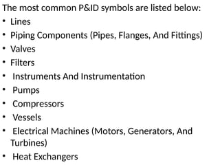
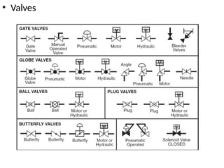
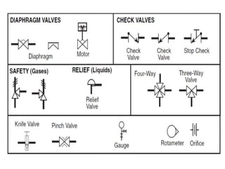
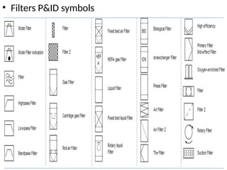
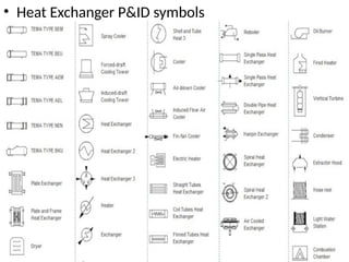
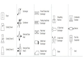
The most commonP&ID symbols are listed below:
• Lines
• Piping Components (Pipes, Flanges, And Fittings)
• Valves
• Filters
• Instruments And Instrumentation
• Pumps
• Compressors
• Vessels
• Electrical Machines (Motors, Generators, And
Turbines)
• Heat Exchangers
![Course Outcomes (CO):
• CO1. Discuss the basic block diagram of Process Control used
in various industries, have a knowledge of Final Control
operation and to study different Piping and Instrumentation
symbols.[KL2]
• CO2. Describe the Characteristics and parameters of process
control and discuss various control modes [KL3]
• CO3. Analyze Discrete State Process control and to analyze
its characteristics[KL3]
• CO4. Analyze Analog Controllers such as electronic
controllers, pneumatic controllers and also analyze the designs
considerations [KL3]
• CO5.Discuss and Analyze Digital to Analog Converters and
analog to digital converters and evaluate the performance
specifications [KL4]](https://image.slidesharecdn.com/module1-250923062839-36d2cbdc/85/Automation-and-process-control-Automation-and-process-control-5-320.jpg)