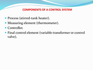
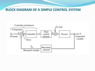
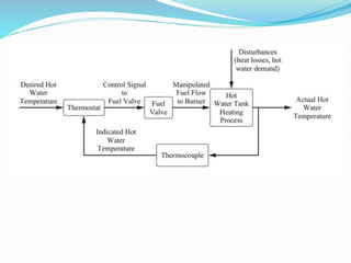
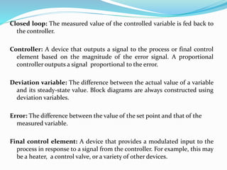
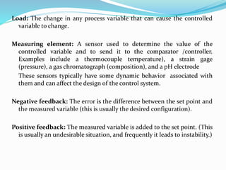
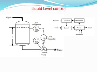
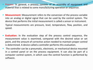
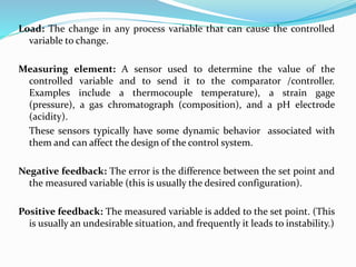
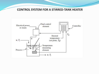
Process Dynamics and Control
(CHPC-306)
Process Control
Enhanced process safety
Satisfying environmental constraints
Meeting ever-stricter product quality specifications
More efficient use of raw materials and energy
Increased profitability
COMPONENTS OF A CONTROL SYSTEM
 Process (stirred-tank heater).
 Measuring element (thermometer).
 Controller.
 Final control element (variable transformer or control
valve).
BLOCK DIAGRAM OF A SIMPLE CONTROL SYSTEM
Closed loop: The measured value of the controlled variable is fed back to
the controller.
Controller: A device that outputs a signal to the process or final control
element based on the magnitude of the error signal. A proportional
controller outputs a signal proportional to the error.
Deviation variable: The difference between the actual value of a variable
and its steady-state value. Block diagrams are always constructed using
deviation variables.
Error: The difference between the value of the set point and that of the
measured variable.
Final control element: A device that provides a modulated input to the
process in response to a signal from the controller. For example, this may
be a heater, a control valve, or a variety of other devices.
Load: The change in any process variable that can cause the controlled
variable to change.
Measuring element: A sensor used to determine the value of the
controlled variable and to send it to the comparator /controller.
Examples include a thermocouple temperature), a strain gage
(pressure), a gas chromatograph (composition), and a pH electrode
These sensors typically have some dynamic behavior associated with
them and can affect the design of the control system.
Negative feedback: The error is the difference between the set point and
the measured variable (this is usually the desired configuration).
Positive feedback: The measured variable is added to the set point. (This
is usually an undesirable situation, and frequently it leads to instability.)
Regulator problem: The goal of a control system for this
type of problem is to enable the system to compensate for
load changes and maintain the controlled variable at the
set point.
Servo problem: The goal of a control system for this type of
problem is to force the system to “track” the requested
set point changes.
Set point: The desired value of the controlled variable.
CONTROL SYSTEM FOR A STIRRED-TANK HEATER
 A liquid stream at a temperature Ti enters an insulated, well-stirred
tank at a constant flow rate w (mass/time).
 It is desired to maintain (or control) the temperature in the tank at TR
by means of the controller. If the measured tank temperature Tm differs
from the desired temperature TR, the controller senses the difference or
error ε
 For that changes the heat input in such a way as to reduce
the magnitude of e.
 If the controller changes the heat input to the tank by an amount that is
proportional to e, we have proportional control.
 It is indicated that the source of heat input q may be electricity
or steam.
 If an electrical source were used, the final control element
might be a variable transformer that is used to adjust current to
a resistance heating element
 If steam were used, the final control element would be a
control valve that adjusts the flow of steam.
 In either case, the output signal from the controller should
adjust q in such a way as to
maintain control of the temperature in the tank.
Negative Feedback
 The feedback principle, which involves the use of the controlled variable
T to maintain itself at a desired value TR.
 Negative feedback ensures that the difference between TR and Tm is
used to adjust the control element so that the tendency is to reduce the
error.
 For example, assume that the system is at steady state and that T= Tm =
TR. If the load Ti should increase, T and Tm would start to increase,
which would cause the error e to become negative.
 With proportional control, the decrease in error would cause the
controller and final control element to decrease the flow of heat to the
system, with the result that the flow of heat would eventually be reduced
to a value such that T approaches TR .
Liquid Level control
 Process: In general, a process consists of an assembly of equipment and
material that is related to some manufacturing operation or sequence.
 Measurement: Measurement refers to the conversion of the process variable
into an analog or digital signal that can be used by the control system. The
device that performs the initial measurement is called a sensor or instrument.
Typical measurements are pressure, level, temperature, flow, position, and
speed.
 Evaluation: In the evaluation step of the process control sequence, the
measurement value is examined, compared with the desired value or set
point, and the amount of corrective action needed to maintain proper control
is determined. A device called a controller performs this evaluation.
 The controller can be a pneumatic, electronic, or mechanical device mounted
in a control panel or on the process equipment. It can also be part of a
computer control system, in which case the control function is performed by
software.
 Control: he control element in a control loop is the device that exerts a
direct influence on the process or manufacturing sequence. This final
control element accepts an input from the controller and transforms it into
some proportional operation that is performed on the process. In most
cases, this final control element will be a control valve that adjusts the flow
of fluid in a process.
 Devices such as electrical motors, pumps, and dampers are also
used as control elements.
Laplace Transform
 The Laplace transform method provides an efficient way to solve linear,
ordinary, differential equations with constant coefficients.
 Laplace transform of a function f (t) is defined to be F (s) according to
the equation
Find the Laplace transform of the function
Tutorial 1
Find the f (t) value
Also f(t)
MERCURY THERMOMETER:
Consider the thermometer to be located in a flowing stream of fluid for which the
temperature x varies with time. The response of thermometer is y for a particular change
in surrounding environment x.
Overall Transfer Function
Content of notes is being used for academic purposes only, and is intended
only for students (Btech 3rd year) NIT JALANDHAR.
RESPONSES OF FIRST-ORDER : SYSTEMS TO COMMON INPUTS
As t »∞, Sinusoid Response is
RESPONSES OF FIRST ORDER SYSTEMS IN CASE OF DIFFERENT
INPUTS
From this figure, it can be seen that interaction slows up the response. At any time
t1 following the introduction of the step input, q1 for the interacting case will be
less than for the noninteracting case with the result that h2 (or q2 ) will increase at
a slower rate.
The unit-step responses for the two cases are plotted to
show the effect of interaction
NONINTERACTING SYSTEMS IN SERIES
Transfer lag is
increased as the
number of stages
increases
RESPONSES OF SECOND-ORDER :
Examples of second order system:
 Multiple Capacity Systems in Series
 Working of manometer
 Damping Vibrator
 Controlled Systems
 Chemical Process System
Characteristic Equation
Y ( t) is plotted against the dimensionless variable t /τ for several
values of τ.
for τ < 1 all the response curves are oscillatory in nature and
become less oscillatory as τ is increased. The response of a
second-order system for τ < 1 is said to be underdamped.
What is the physical significance of an underdamped response?
Using the manometer as an example, if we step-change the
pressure difference across an underdamped manometer, the
liquid levels in the two legs will oscillate before stabilizing.
The oscillations are characteristic of an underdamped response.
Natural period of oscillation:
If the damping is eliminated, the system oscillates continuously
without attenuation in amplitude. Under these “natural” or
undamped conditions, the radian frequency is 1/τ. This frequency
is referred to as the natural frequency.
Settling Time :
 Overshoot is a measure of how much the response
exceeds the ultimate value.
 Why are we concerned about overshoot? The temperature
in our chemical reactor cannot be allowed to exceed a
specified temperature to protect the catalyst from
deactivation.
or
 If it’s a level control system, we don’t want the tank to
overflow. If we know these physical limitations, we can
determine allowable values of τ and choose our control
system parameters to be sure to stay with in those limits.
TRANSPORTATION LAG:
 The temperature x of the entering fluid varies with time, and
it is desired to find the response of the outlet temperature
y(t) in terms of a transfer function.
 If a step change were made in x ( t) at t = 0, the change would
not be detected at the end of the tube until τ second later,
where τ is the time required for the entering fluid to pass
through the tube.
COMPONENTS OF A CONTROL SYSTEM
 Process (stirred-tank heater).
 Measuring element (thermometer).
 Controller.
 Final control element (variable transformer or control
valve).
BLOCK DIAGRAM OF A SIMPLE CONTROL SYSTEM
Closed loop: The measured value of the controlled variable is fed back to
the controller.
Controller: A device that outputs a signal to the process or final control
element based on the magnitude of the error signal. A proportional
controller outputs a signal proportional to the error.
Deviation variable: The difference between the actual value of a variable
and its steady-state value. Block diagrams are always constructed using
deviation variables.
Error: The difference between the value of the set point and that of the
measured variable.
Final control element: A device that provides a modulated input to the
process in response to a signal from the controller. For example, this may
be a heater, a control valve, or a variety of other devices.
Load: The change in any process variable that can cause the controlled
variable to change.
Measuring element: A sensor used to determine the value of the
controlled variable and to send it to the comparator /controller.
Examples include a thermocouple temperature), a strain gage
(pressure), a gas chromatograph (composition), and a pH electrode
(acidity).
These sensors typically have some dynamic behavior associated with
them and can affect the design of the control system.
Negative feedback: The error is the difference between the set point and
the measured variable (this is usually the desired configuration).
Positive feedback: The measured variable is added to the set point. (This
is usually an undesirable situation, and frequently it leads to instability.)
Regulator problem: The goal of a control system for this
type of problem is to enable the system to compensate for
load changes and maintain the controlled variable at the
set point.
Servo problem: The goal of a control system for this type of
problem is to force the system to “track” the requested
set point changes.
Set point: The desired value of the controlled variable.
CONTROL SYSTEM FOR A STIRRED-TANK HEATER
 A liquid stream at a temperature Ti enters an insulated, well-stirred
tank at a constant flow rate w (mass/time).
 It is desired to maintain (or control) the temperature in the tank at TR
by means of the controller. If the measured tank temperature Tm differs
from the desired temperature TR, the controller senses the difference or
error ε
 For that changes the heat input in such a way as to reduce
the magnitude of e.
 If the controller changes the heat input to the tank by an amount that is
proportional to e, we have proportional control.
 It is indicated that the source of heat input q may be electricity
or steam.
 If an electrical source were used, the final control element
might be a variable transformer that is used to adjust current to
a resistance heating element
 If steam were used, the final control element would be a
control valve that adjusts the flow of steam.
 In either case, the output signal from the controller should
adjust q in such a way as to
maintain control of the temperature in the tank.
Negative Feedback
 The feedback principle, which involves the use of the controlled variable
T to maintain itself at a desired value TR.
 Negative feedback ensures that the difference between TR and Tm is
used to adjust the control element so that the tendency is to reduce the
error.
 For example, assume that the system is at steady state and that T= Tm =
TR. If the load Ti should increase, T and Tm would start to increase,
which would cause the error e to become negative.
 With proportional control, the decrease in error would cause the
controller and final control element to decrease the flow of heat to the
system, with the result that the flow of heat would eventually be reduced
to a value such that T approaches TR .
Positive Feedback
 If the signal to the comparator were obtained by adding TR and Tm, we
would have a positive feedback system, which is inherently unstable. If
again assume that the system is at steady state and that T= Tm = TR .
 If Ti were to increase, T and Tm would increase, which would cause the
signal from the comparator to increase, with the result that the heat to
the system would increase.
 However, this action, which is just the opposite of that needed, would
cause T to increase further.
 It should be clear that this situation would cause T to “run away” and
control would not be achieved.
Control Valve
 The control action in any control loop system, is executed by the final
control element. The most common type of final control element used
in chemical and other process control is the control valve.
 A control valve is normally driven by a diaphragm type pneumatic
actuator that throttles the flow of the manipulating variable for
obtaining the desired control action.
 A control valve essentially consists of a plug and a stem. The stem can
be raised or lowered by air pressure and the plug changes the
effective area of an orifice in the flow path.
 A typical control valve action can be explained using following Fig.
When the air pressure increases, the downward force of the
diaphragm moves the stem downward against the spring
Control valves are available in different types and shapes. They can be
Classified in different ways; based on: (a) action, (b) number of plugs, and (c)
flow characteristics.
1. Action: Control valves operated through pneumatic actuators can
be either (i) air to open, or (ii) air to close.
 In the air-to-close valve, as the air pressure increases, the plug moves
downward and restricts the flow of fluid through the valve.
 In the air-to-open valve, the valve opens and allows greater flow as the
valve-top air pressure increases.
 The choice between air-to-open and air-to-close is usually made based on
safety considerations. If the instrument air pressure fails. we would like the
valve to fail in a safe position for the process.
 For example, if the control valve were on the cooling water inlet to a cooling
jacket for an exothermic chemical reactor, we would want the valve to fail
open so that we do not lose cooling water flow to the reactor. In such a
situation, we would choose an air-to-close valve.
AIR-TO-OPEN (Fail closed) AND AIR-TO-CLOSE (Fail open)
Valve motors are often constructed so that the valve stem position is
proportional to the valve-top pressure. Most commercial valves move from
fully open to fully closed as the valve-top pressure changes from 3 to 15 psig.
2. NUMBER OF PLUGS: Control valves can also be characterized in terms of the
number of plugs present, as single-seated valve and double-seated valve
3. Flow Characteristics: It describes how the flow rate changes with the
movement or lift of the stem. The shape of the plug primarily decides the
flow characteristics.
 The function of a control valve is to vary the flow of fluid through the valve by
means of a change of pressure to the valve top.
 The relation between the flow through the valve and the valve stem position
(or lift) is called the valve characteristic, which can be conveniently described
by means of a graph as shown in Fig. where three types of characteristics are

PDC NOTES (JAN 2021).pptx

  • 1.
    Process Dynamics andControl (CHPC-306)
  • 2.
    Process Control Enhanced processsafety Satisfying environmental constraints Meeting ever-stricter product quality specifications More efficient use of raw materials and energy Increased profitability
  • 3.
    COMPONENTS OF ACONTROL SYSTEM  Process (stirred-tank heater).  Measuring element (thermometer).  Controller.  Final control element (variable transformer or control valve).
  • 4.
    BLOCK DIAGRAM OFA SIMPLE CONTROL SYSTEM
  • 6.
    Closed loop: Themeasured value of the controlled variable is fed back to the controller. Controller: A device that outputs a signal to the process or final control element based on the magnitude of the error signal. A proportional controller outputs a signal proportional to the error. Deviation variable: The difference between the actual value of a variable and its steady-state value. Block diagrams are always constructed using deviation variables. Error: The difference between the value of the set point and that of the measured variable. Final control element: A device that provides a modulated input to the process in response to a signal from the controller. For example, this may be a heater, a control valve, or a variety of other devices.
  • 7.
    Load: The changein any process variable that can cause the controlled variable to change. Measuring element: A sensor used to determine the value of the controlled variable and to send it to the comparator /controller. Examples include a thermocouple temperature), a strain gage (pressure), a gas chromatograph (composition), and a pH electrode These sensors typically have some dynamic behavior associated with them and can affect the design of the control system. Negative feedback: The error is the difference between the set point and the measured variable (this is usually the desired configuration). Positive feedback: The measured variable is added to the set point. (This is usually an undesirable situation, and frequently it leads to instability.)
  • 8.
    Regulator problem: Thegoal of a control system for this type of problem is to enable the system to compensate for load changes and maintain the controlled variable at the set point. Servo problem: The goal of a control system for this type of problem is to force the system to “track” the requested set point changes. Set point: The desired value of the controlled variable.
  • 9.
    CONTROL SYSTEM FORA STIRRED-TANK HEATER
  • 10.
     A liquidstream at a temperature Ti enters an insulated, well-stirred tank at a constant flow rate w (mass/time).  It is desired to maintain (or control) the temperature in the tank at TR by means of the controller. If the measured tank temperature Tm differs from the desired temperature TR, the controller senses the difference or error ε  For that changes the heat input in such a way as to reduce the magnitude of e.  If the controller changes the heat input to the tank by an amount that is proportional to e, we have proportional control.
  • 11.
     It isindicated that the source of heat input q may be electricity or steam.  If an electrical source were used, the final control element might be a variable transformer that is used to adjust current to a resistance heating element  If steam were used, the final control element would be a control valve that adjusts the flow of steam.  In either case, the output signal from the controller should adjust q in such a way as to maintain control of the temperature in the tank.
  • 12.
    Negative Feedback  Thefeedback principle, which involves the use of the controlled variable T to maintain itself at a desired value TR.  Negative feedback ensures that the difference between TR and Tm is used to adjust the control element so that the tendency is to reduce the error.  For example, assume that the system is at steady state and that T= Tm = TR. If the load Ti should increase, T and Tm would start to increase, which would cause the error e to become negative.  With proportional control, the decrease in error would cause the controller and final control element to decrease the flow of heat to the system, with the result that the flow of heat would eventually be reduced to a value such that T approaches TR .
  • 13.
  • 14.
     Process: Ingeneral, a process consists of an assembly of equipment and material that is related to some manufacturing operation or sequence.  Measurement: Measurement refers to the conversion of the process variable into an analog or digital signal that can be used by the control system. The device that performs the initial measurement is called a sensor or instrument. Typical measurements are pressure, level, temperature, flow, position, and speed.  Evaluation: In the evaluation step of the process control sequence, the measurement value is examined, compared with the desired value or set point, and the amount of corrective action needed to maintain proper control is determined. A device called a controller performs this evaluation.  The controller can be a pneumatic, electronic, or mechanical device mounted in a control panel or on the process equipment. It can also be part of a computer control system, in which case the control function is performed by software.
  • 15.
     Control: hecontrol element in a control loop is the device that exerts a direct influence on the process or manufacturing sequence. This final control element accepts an input from the controller and transforms it into some proportional operation that is performed on the process. In most cases, this final control element will be a control valve that adjusts the flow of fluid in a process.  Devices such as electrical motors, pumps, and dampers are also used as control elements.
  • 16.
    Laplace Transform  TheLaplace transform method provides an efficient way to solve linear, ordinary, differential equations with constant coefficients.  Laplace transform of a function f (t) is defined to be F (s) according to the equation Find the Laplace transform of the function
  • 19.
    Tutorial 1 Find thef (t) value Also f(t)
  • 20.
    MERCURY THERMOMETER: Consider thethermometer to be located in a flowing stream of fluid for which the temperature x varies with time. The response of thermometer is y for a particular change in surrounding environment x. Overall Transfer Function Content of notes is being used for academic purposes only, and is intended only for students (Btech 3rd year) NIT JALANDHAR.
  • 22.
    RESPONSES OF FIRST-ORDER: SYSTEMS TO COMMON INPUTS As t »∞, Sinusoid Response is
  • 23.
    RESPONSES OF FIRSTORDER SYSTEMS IN CASE OF DIFFERENT INPUTS
  • 25.
    From this figure,it can be seen that interaction slows up the response. At any time t1 following the introduction of the step input, q1 for the interacting case will be less than for the noninteracting case with the result that h2 (or q2 ) will increase at a slower rate. The unit-step responses for the two cases are plotted to show the effect of interaction
  • 26.
    NONINTERACTING SYSTEMS INSERIES Transfer lag is increased as the number of stages increases
  • 27.
  • 28.
    Examples of secondorder system:  Multiple Capacity Systems in Series  Working of manometer  Damping Vibrator  Controlled Systems  Chemical Process System
  • 29.
  • 30.
    Y ( t)is plotted against the dimensionless variable t /τ for several values of τ. for τ < 1 all the response curves are oscillatory in nature and become less oscillatory as τ is increased. The response of a second-order system for τ < 1 is said to be underdamped. What is the physical significance of an underdamped response? Using the manometer as an example, if we step-change the pressure difference across an underdamped manometer, the liquid levels in the two legs will oscillate before stabilizing. The oscillations are characteristic of an underdamped response.
  • 34.
    Natural period ofoscillation: If the damping is eliminated, the system oscillates continuously without attenuation in amplitude. Under these “natural” or undamped conditions, the radian frequency is 1/τ. This frequency is referred to as the natural frequency. Settling Time :
  • 35.
     Overshoot isa measure of how much the response exceeds the ultimate value.  Why are we concerned about overshoot? The temperature in our chemical reactor cannot be allowed to exceed a specified temperature to protect the catalyst from deactivation. or  If it’s a level control system, we don’t want the tank to overflow. If we know these physical limitations, we can determine allowable values of τ and choose our control system parameters to be sure to stay with in those limits.
  • 36.
    TRANSPORTATION LAG:  Thetemperature x of the entering fluid varies with time, and it is desired to find the response of the outlet temperature y(t) in terms of a transfer function.  If a step change were made in x ( t) at t = 0, the change would not be detected at the end of the tube until τ second later, where τ is the time required for the entering fluid to pass through the tube.
  • 40.
    COMPONENTS OF ACONTROL SYSTEM  Process (stirred-tank heater).  Measuring element (thermometer).  Controller.  Final control element (variable transformer or control valve).
  • 41.
    BLOCK DIAGRAM OFA SIMPLE CONTROL SYSTEM
  • 42.
    Closed loop: Themeasured value of the controlled variable is fed back to the controller. Controller: A device that outputs a signal to the process or final control element based on the magnitude of the error signal. A proportional controller outputs a signal proportional to the error. Deviation variable: The difference between the actual value of a variable and its steady-state value. Block diagrams are always constructed using deviation variables. Error: The difference between the value of the set point and that of the measured variable. Final control element: A device that provides a modulated input to the process in response to a signal from the controller. For example, this may be a heater, a control valve, or a variety of other devices.
  • 43.
    Load: The changein any process variable that can cause the controlled variable to change. Measuring element: A sensor used to determine the value of the controlled variable and to send it to the comparator /controller. Examples include a thermocouple temperature), a strain gage (pressure), a gas chromatograph (composition), and a pH electrode (acidity). These sensors typically have some dynamic behavior associated with them and can affect the design of the control system. Negative feedback: The error is the difference between the set point and the measured variable (this is usually the desired configuration). Positive feedback: The measured variable is added to the set point. (This is usually an undesirable situation, and frequently it leads to instability.)
  • 44.
    Regulator problem: Thegoal of a control system for this type of problem is to enable the system to compensate for load changes and maintain the controlled variable at the set point. Servo problem: The goal of a control system for this type of problem is to force the system to “track” the requested set point changes. Set point: The desired value of the controlled variable.
  • 45.
    CONTROL SYSTEM FORA STIRRED-TANK HEATER
  • 46.
     A liquidstream at a temperature Ti enters an insulated, well-stirred tank at a constant flow rate w (mass/time).  It is desired to maintain (or control) the temperature in the tank at TR by means of the controller. If the measured tank temperature Tm differs from the desired temperature TR, the controller senses the difference or error ε  For that changes the heat input in such a way as to reduce the magnitude of e.  If the controller changes the heat input to the tank by an amount that is proportional to e, we have proportional control.
  • 47.
     It isindicated that the source of heat input q may be electricity or steam.  If an electrical source were used, the final control element might be a variable transformer that is used to adjust current to a resistance heating element  If steam were used, the final control element would be a control valve that adjusts the flow of steam.  In either case, the output signal from the controller should adjust q in such a way as to maintain control of the temperature in the tank.
  • 48.
    Negative Feedback  Thefeedback principle, which involves the use of the controlled variable T to maintain itself at a desired value TR.  Negative feedback ensures that the difference between TR and Tm is used to adjust the control element so that the tendency is to reduce the error.  For example, assume that the system is at steady state and that T= Tm = TR. If the load Ti should increase, T and Tm would start to increase, which would cause the error e to become negative.  With proportional control, the decrease in error would cause the controller and final control element to decrease the flow of heat to the system, with the result that the flow of heat would eventually be reduced to a value such that T approaches TR .
  • 49.
    Positive Feedback  Ifthe signal to the comparator were obtained by adding TR and Tm, we would have a positive feedback system, which is inherently unstable. If again assume that the system is at steady state and that T= Tm = TR .  If Ti were to increase, T and Tm would increase, which would cause the signal from the comparator to increase, with the result that the heat to the system would increase.  However, this action, which is just the opposite of that needed, would cause T to increase further.  It should be clear that this situation would cause T to “run away” and control would not be achieved.
  • 50.
    Control Valve  Thecontrol action in any control loop system, is executed by the final control element. The most common type of final control element used in chemical and other process control is the control valve.  A control valve is normally driven by a diaphragm type pneumatic actuator that throttles the flow of the manipulating variable for obtaining the desired control action.  A control valve essentially consists of a plug and a stem. The stem can be raised or lowered by air pressure and the plug changes the effective area of an orifice in the flow path.  A typical control valve action can be explained using following Fig. When the air pressure increases, the downward force of the diaphragm moves the stem downward against the spring
  • 51.
    Control valves areavailable in different types and shapes. They can be Classified in different ways; based on: (a) action, (b) number of plugs, and (c) flow characteristics.
  • 52.
    1. Action: Controlvalves operated through pneumatic actuators can be either (i) air to open, or (ii) air to close.  In the air-to-close valve, as the air pressure increases, the plug moves downward and restricts the flow of fluid through the valve.  In the air-to-open valve, the valve opens and allows greater flow as the valve-top air pressure increases.  The choice between air-to-open and air-to-close is usually made based on safety considerations. If the instrument air pressure fails. we would like the valve to fail in a safe position for the process.  For example, if the control valve were on the cooling water inlet to a cooling jacket for an exothermic chemical reactor, we would want the valve to fail open so that we do not lose cooling water flow to the reactor. In such a situation, we would choose an air-to-close valve.
  • 53.
    AIR-TO-OPEN (Fail closed)AND AIR-TO-CLOSE (Fail open) Valve motors are often constructed so that the valve stem position is proportional to the valve-top pressure. Most commercial valves move from fully open to fully closed as the valve-top pressure changes from 3 to 15 psig.
  • 54.
    2. NUMBER OFPLUGS: Control valves can also be characterized in terms of the number of plugs present, as single-seated valve and double-seated valve 3. Flow Characteristics: It describes how the flow rate changes with the movement or lift of the stem. The shape of the plug primarily decides the flow characteristics.  The function of a control valve is to vary the flow of fluid through the valve by means of a change of pressure to the valve top.  The relation between the flow through the valve and the valve stem position (or lift) is called the valve characteristic, which can be conveniently described by means of a graph as shown in Fig. where three types of characteristics are