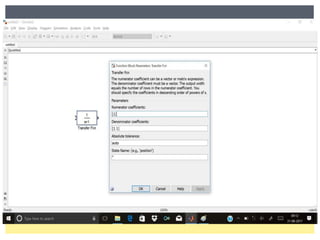
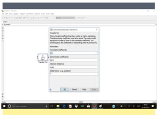
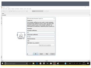
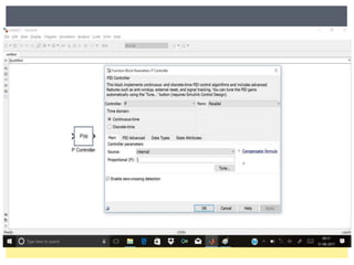
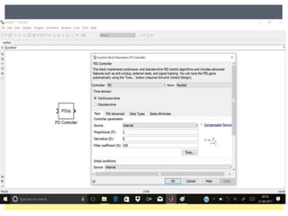
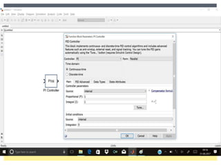
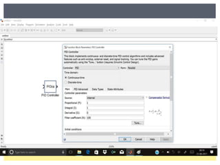
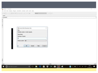
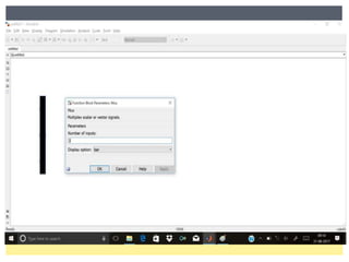
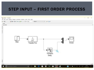
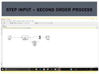
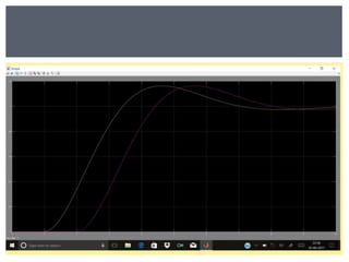
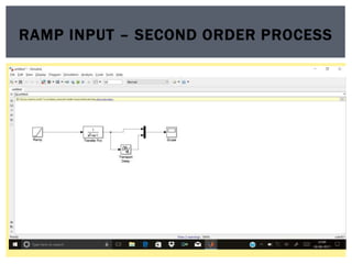
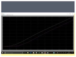
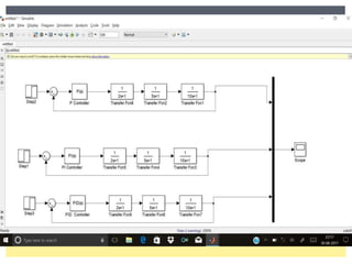
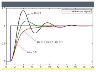
Presented by
LAKSHMIPRIYA J,
ASSISTANT PROFESSOR,
DEPT. OF CHEMICAL ENGINEERING,
ESEC.
PROCESS CONTROL IN
CHEMICAL ENGINEERING
BY USING MATLAB
 Introduction to Process control
 Basic concepts in process control
 Introduction to MATLAB
 Introduction to Simulink in MATLAB
 Examples
OVERVIEW ABOUT THIS WORKSHOP
 Chemical industry – we have numbers of unit
operations.
 For example – Reactors, Distillation Columns,
Pumps and Compressors.
 Now we construct a chemical plant, we need to
assemble few these unit operations.
INTRODUCTION TO PROCESS CONTROL
 The chemical plant receives raw material and convert
into desired product using available sources, in a most
economic way.
Raw materials Product
OBJECTIVES OF CHEMICAL PLANT
Chemical Plant
 We need to achieve this objectives, we need some
external requirements. These are:
 Safety
 Product Specifications – both Quality and Quantity
 Environmental Requirements
 Operational Constants
 Economics
REQUIREMENTS
To achieve this
requirements,
we need
control system
 Suppress the influence of external disturbances.
 Ensuring the stability of the chemical process.
 Optimizing the performance of a chemical process.
NEED FOR CONTROL SYSTEM
 Discrete – manufacturing, Motion and Packaging applications.
For example, Robotic assembly in automotive production.
 Batch – Some applications require specific quantities of raw
material in a specific way and specific time to produce the end
product. For example, Production of adhesives, glues, food,
medicine and beverages. This process generally used to
produces relatively low quantity of product pre year.
TYPES OF PROCESSES USING PROCESS
CONTROL
 Continuous – All raw materials are mixed together
and product coming out of the process. Some
important chemical processes are the production of
fuels, chemicals and plastics. This process are used
to produce very large quantities of product per year.
CONT..
 Input Variables
 Manipulated Variables – Values can be adjusted by
operator or control mechanisms.
 Disturbances – Values can’t be changed
 Output variables
 Measured output
 Unmeasured output
CLASSIFICATIONS OF VARIABLES IN PC
 Step
 Ramp
 Impulse
 Sinusoidal
TYPES OF INPUT SIGNALS
CONTROL PROCESS
Process
Controller
Disturbances
Set Point (SP)
Adjustment Measurement
Control
Loop
Process
Variable
(PV)
Controlled
Output
(CO)
 Set Point (SP) – Desired or target value of an process
variable.
 Process Variable (PV) – Process parameter will be
monitored in the process.
 Disturbances – internal and external disturbances that
affects the process.
IMPORTANT TERMS
 Control system divided into two types:
 Feedback Control System
 Feed forward Control System
BLOCK DIAGRAM OF CONTROL SYSTEM
 This system will react only after detecting the error
signal from the process. In this system, no action
control action will be taken until the error affects the
process variable.
FEEDBACK CONTROL SYSTEM
 This system, the disturbances will be directly
measured and corrective action takes place.
 In this system, the process variable doesn’t change.
Input Output
FEED FORWARD CONTROL SYSTEM
su
m Controller Process
Disturbances
 Compares the controlled output and set point.
 Based on this comparison the control system divided
into two types:
 Negative Feedback control system e = R-B
 Positive Feedback control system e = R+B
COMPARATOR
Laplace transform of output variable
 G(S) =
Laplace transform of Input variable
HOW DID YOU UNDERSTAND THE
RESPONSE OF CONTROL SYSTEM
 Pneumatically operated controllers are widely used in chemical
process control in industrial applications.
 Here the compressed air is used to open and close the control
valve.
 Types of controllers:
 Proportional Controller
 Proportional Derivative Controller
 Proportional Integral Controller
 Proportional Integral and Derivative Controller
 ON/OFF Controller
TYPES OF CONTROLLER
 The measured process variable (PV) first begins to
respond.
TIME DELAY / TRANSPORTATION LAG
Why Controller Tuning is Important
 The control system acts as the nervous system for the
plant. It provides sensing, analysis and control of the
physical process.
 When a control system is at properly tuned, the
process variability is reduced, efficiency is maximized,
energy costs are minimized, and production rates can
be increased.
TUNING OF CONTROLLERS
 Controller tuning refers to the selection of tuning parameters
to ensure the best response of the controller.
 Choose tuning that is too slow, and the response will be
sluggish.
 The controller will not handle upsets, and it will take too long
to reach set point.
CONTROLLER TUNING
 Cohoon – Coon Method – Open loop system
 Ziegler – Nichols Method – Closed loop system
TUNING METHODS
Open loop system –
No action to error
signals. Only the set
point will vary by the
operator.
Closed loop system
– Controller takes
action to error. The
set point will be
constant.
MATLAB
 MATLAB is a commercial “Matrix Laboratory” package with
operates as an interactive programming environment.
 It is well adopted to numerical experiments.
 High – Performance language for technical computing.
INTRODUCTION TO MATLAB
 Algorithm development
 Data Acquisition
 Modeling and Simulation
 Data Analysis, Exploration and Visualization
 Scientific and Engineering Graphics
 Application Development including graphical user interface
building
USES
MATLAB WINDOW
TOOLS
 SIMULINK is an extension to MATLAB which uses a icon driven
interface for the construction of block diagrams representation
of a PROCESS.
 Steps involved in Simulink solution:
 Creating the block diagram
 Specify the block parameters
 Setting up the solver
 Running the simulation
SIMULINK
SIMULINK
SIMULINK LIBRARY BROWSER
RESPONSE OF TIME
DELAY FOR DIFFERENT
ORDER PROCESS FOR
DIFFERENT TYPES
INPUTS
STEP INPUT – FIRST ORDER PROCESS
RAMP INPUT – FIRST ORDER PROCESS
SINE INPUT – FIRST ORDER PROCESS
STEP INPUT – SECOND ORDER PROCESS
RAMP INPUT – SECOND ORDER PROCESS
SINE INPUT – SECOND ORDER PROCESS
TUNING OF PID
CONTROLLER
OPEN LOOP DIAGRAM (COHOON – COON
METHOD)
CLOSED LOOP SYSTEM (ZIEGLER
NICHOLS METHOD)
Ko
PV
 P – Controller Kp = Ko / 2
 PI – Controller Kp = Ko / 2.2
tI = PV / 1.2
KI = 1 / tI
 PID – Controller
Kp = Ko / 1.7
tI = PV / 2
KI = 1 / tI
t D = PV / 8
KD = 1 / t D
Process Control in Chemical Engineering by MATLAB

Process Control in Chemical Engineering by MATLAB

  • 1.
    Presented by LAKSHMIPRIYA J, ASSISTANTPROFESSOR, DEPT. OF CHEMICAL ENGINEERING, ESEC. PROCESS CONTROL IN CHEMICAL ENGINEERING BY USING MATLAB
  • 2.
     Introduction toProcess control  Basic concepts in process control  Introduction to MATLAB  Introduction to Simulink in MATLAB  Examples OVERVIEW ABOUT THIS WORKSHOP
  • 3.
     Chemical industry– we have numbers of unit operations.  For example – Reactors, Distillation Columns, Pumps and Compressors.  Now we construct a chemical plant, we need to assemble few these unit operations. INTRODUCTION TO PROCESS CONTROL
  • 4.
     The chemicalplant receives raw material and convert into desired product using available sources, in a most economic way. Raw materials Product OBJECTIVES OF CHEMICAL PLANT Chemical Plant
  • 5.
     We needto achieve this objectives, we need some external requirements. These are:  Safety  Product Specifications – both Quality and Quantity  Environmental Requirements  Operational Constants  Economics REQUIREMENTS To achieve this requirements, we need control system
  • 6.
     Suppress theinfluence of external disturbances.  Ensuring the stability of the chemical process.  Optimizing the performance of a chemical process. NEED FOR CONTROL SYSTEM
  • 7.
     Discrete –manufacturing, Motion and Packaging applications. For example, Robotic assembly in automotive production.  Batch – Some applications require specific quantities of raw material in a specific way and specific time to produce the end product. For example, Production of adhesives, glues, food, medicine and beverages. This process generally used to produces relatively low quantity of product pre year. TYPES OF PROCESSES USING PROCESS CONTROL
  • 8.
     Continuous –All raw materials are mixed together and product coming out of the process. Some important chemical processes are the production of fuels, chemicals and plastics. This process are used to produce very large quantities of product per year. CONT..
  • 9.
     Input Variables Manipulated Variables – Values can be adjusted by operator or control mechanisms.  Disturbances – Values can’t be changed  Output variables  Measured output  Unmeasured output CLASSIFICATIONS OF VARIABLES IN PC
  • 10.
     Step  Ramp Impulse  Sinusoidal TYPES OF INPUT SIGNALS
  • 11.
    CONTROL PROCESS Process Controller Disturbances Set Point(SP) Adjustment Measurement Control Loop Process Variable (PV) Controlled Output (CO)
  • 12.
     Set Point(SP) – Desired or target value of an process variable.  Process Variable (PV) – Process parameter will be monitored in the process.  Disturbances – internal and external disturbances that affects the process. IMPORTANT TERMS
  • 13.
     Control systemdivided into two types:  Feedback Control System  Feed forward Control System BLOCK DIAGRAM OF CONTROL SYSTEM
  • 14.
     This systemwill react only after detecting the error signal from the process. In this system, no action control action will be taken until the error affects the process variable. FEEDBACK CONTROL SYSTEM
  • 15.
     This system,the disturbances will be directly measured and corrective action takes place.  In this system, the process variable doesn’t change. Input Output FEED FORWARD CONTROL SYSTEM su m Controller Process Disturbances
  • 16.
     Compares thecontrolled output and set point.  Based on this comparison the control system divided into two types:  Negative Feedback control system e = R-B  Positive Feedback control system e = R+B COMPARATOR
  • 17.
    Laplace transform ofoutput variable  G(S) = Laplace transform of Input variable HOW DID YOU UNDERSTAND THE RESPONSE OF CONTROL SYSTEM
  • 18.
     Pneumatically operatedcontrollers are widely used in chemical process control in industrial applications.  Here the compressed air is used to open and close the control valve.  Types of controllers:  Proportional Controller  Proportional Derivative Controller  Proportional Integral Controller  Proportional Integral and Derivative Controller  ON/OFF Controller TYPES OF CONTROLLER
  • 19.
     The measuredprocess variable (PV) first begins to respond. TIME DELAY / TRANSPORTATION LAG
  • 20.
    Why Controller Tuningis Important  The control system acts as the nervous system for the plant. It provides sensing, analysis and control of the physical process.  When a control system is at properly tuned, the process variability is reduced, efficiency is maximized, energy costs are minimized, and production rates can be increased. TUNING OF CONTROLLERS
  • 21.
     Controller tuningrefers to the selection of tuning parameters to ensure the best response of the controller.  Choose tuning that is too slow, and the response will be sluggish.  The controller will not handle upsets, and it will take too long to reach set point. CONTROLLER TUNING
  • 22.
     Cohoon –Coon Method – Open loop system  Ziegler – Nichols Method – Closed loop system TUNING METHODS Open loop system – No action to error signals. Only the set point will vary by the operator. Closed loop system – Controller takes action to error. The set point will be constant.
  • 23.
  • 24.
     MATLAB isa commercial “Matrix Laboratory” package with operates as an interactive programming environment.  It is well adopted to numerical experiments.  High – Performance language for technical computing. INTRODUCTION TO MATLAB
  • 25.
     Algorithm development Data Acquisition  Modeling and Simulation  Data Analysis, Exploration and Visualization  Scientific and Engineering Graphics  Application Development including graphical user interface building USES
  • 26.
  • 27.
  • 28.
     SIMULINK isan extension to MATLAB which uses a icon driven interface for the construction of block diagrams representation of a PROCESS.  Steps involved in Simulink solution:  Creating the block diagram  Specify the block parameters  Setting up the solver  Running the simulation SIMULINK
  • 29.
  • 30.
  • 45.
    RESPONSE OF TIME DELAYFOR DIFFERENT ORDER PROCESS FOR DIFFERENT TYPES INPUTS
  • 46.
    STEP INPUT –FIRST ORDER PROCESS
  • 48.
    RAMP INPUT –FIRST ORDER PROCESS
  • 50.
    SINE INPUT –FIRST ORDER PROCESS
  • 52.
    STEP INPUT –SECOND ORDER PROCESS
  • 54.
    RAMP INPUT –SECOND ORDER PROCESS
  • 56.
    SINE INPUT –SECOND ORDER PROCESS
  • 58.
  • 59.
    OPEN LOOP DIAGRAM(COHOON – COON METHOD)
  • 61.
    CLOSED LOOP SYSTEM(ZIEGLER NICHOLS METHOD)
  • 62.
  • 63.
     P –Controller Kp = Ko / 2  PI – Controller Kp = Ko / 2.2 tI = PV / 1.2 KI = 1 / tI
  • 64.
     PID –Controller Kp = Ko / 1.7 tI = PV / 2 KI = 1 / tI t D = PV / 8 KD = 1 / t D