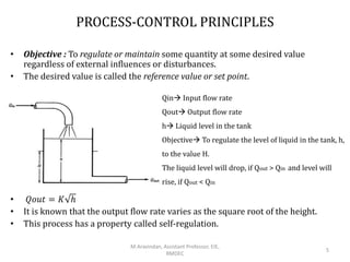
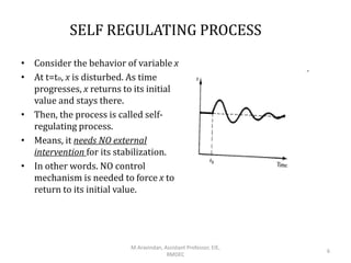
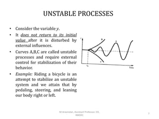
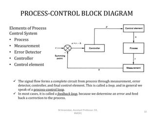
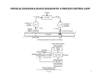
AUTOMATIC PROCESS CONTROL SYSTEMS-
INTRODUCTION
Mr.M.Aravindan
Assistant Professor
EIE-RMDEC
1
M.Aravindan, Assistant Professor, EIE,
RMDEC
TOPICS TO BE DISCUSSED
• AUTOMATIC PROCESS CONTROL – BASIC CONCEPTS
• NEED FOR PROCESS CONTROL
M.Aravindan, Assistant Professor, EIE,
RMDEC
2
I
PROCESS CONTROL – BASIC CONCEPTS
M.Aravindan, Assistant Professor, EIE,
RMDEC
3
Introduction to Process Control
• Human progress from a primitive state to our present complex,
technological world has been marked by learning new and improved
methods to control the environment.
• The term control means methods to force parameters in the
environment to have specific values.
• Example: Maintaining Room Temperature at a Specific value.
• All the elements necessary to accomplish the control objective are
described by the term control system.
• Control Systems:
1) Natural Process Control . Ex. Biological Functions
2) Automatic Control system. Ex. Machines, Electronics and
Computers replace the
human function.
PROCESS-CONTROL PRINCIPLES
• Objective : To regulate or maintain some quantity at some desired value
regardless of external influences or disturbances.
• The desired value is called the reference value or set point.
• 𝑄𝑜𝑢𝑡 = 𝐾 ℎ
• It is known that the output flow rate varies as the square root of the height.
• This process has a property called self-regulation.
Qin Input flow rate
Qout Output flow rate
h Liquid level in the tank
Objective To regulate the level of liquid in the tank, h,
to the value H.
The liquid level will drop, if Qout > Qin and level will
rise, if Qout < Qin
M.Aravindan, Assistant Professor, EIE,
RMDEC
5
SELF REGULATING PROCESS
• Consider the behavior of variable x
• At t=to, x is disturbed. As time
progresses, x returns to its initial
value and stays there.
• Then, the process is called self-
regulating process.
• Means, it needs NO external
intervention for its stabilization.
• In other words. NO control
mechanism is needed to force x to
return to its initial value.
M.Aravindan, Assistant Professor, EIE,
RMDEC
6
UNSTABLE PROCESSES
• Consider the variable y.
• It does not return to its initial
value after it is disturbed by
external influences.
• Curves A,B,C are called unstable
processes and require external
control for stabilization of their
behavior.
• Example: Riding a bicycle is an
attempt to stabilize an unstable
system and we attain that by
pedaling, steering, and leaning
our body right or left.
M.Aravindan, Assistant Professor, EIE,
RMDEC
7
HUMAN-AIDED CONTROL
A human can regulate the level using a sight tube, S, to compare the level, h, to
the objective, H, and adjust a valve to change the level.
• The actual liquid
level or height is
called the controlled
variable.
• The output flow
rate is called the
manipulated
variable or
controlling variable.
M.Aravindan, Assistant Professor, EIE,
RMDEC
8
AUTOMATIC LEVEL-CONTROL SYSTEM
An automatic level-control system replaces the human with a controller
and uses a sensor to measure the level.
When automatic control is applied to systems like the above level system, which are
designed to regulate the value of some variable to a setpoint, it is called process
control.
Automatic Control System is
provided to level system using
• Sensor
• Controller and
• Actuator
M.Aravindan, Assistant Professor, EIE,
RMDEC
9
PROCESS-CONTROL BLOCK DIAGRAM
Elements of Process
Control System
• Process
• Measurement
• Error Detector
• Controller
• Control element
 The signal flow forms a complete circuit from process through measurement, error
detector, controller, and final control element. This is called a loop, and in general we
speak of a process-control loop.
 In most cases, it is called a feedback loop, because we determine an error and feed
back a correction to the process.
M.Aravindan, Assistant Professor, EIE,
RMDEC
10
PHYSICAL DIAGRAM & BLOCK DIAGRAM OF A PROCESS CONTROL LOOP
M.Aravindan, Assistant Professor, EIE,
RMDEC
11
II
PROCESS CONTROL – NECESSITY
M.Aravindan, Assistant Professor, EIE,
RMDEC
12
NEED FOR PROCESS CONTROL
There are 3 general classes of needs that a control system is
called on to satisfy:
• Suppressing the influence of external disturbances
• Ensuring the stability of a process
• Optimizing the performance of a process
M.Aravindan, Assistant Professor, EIE,
RMDEC
13
1. SUPPRESS THE INFLUENCE OF EXTERNAL DISTURBANCE
Ex: Controlling the operation of a stirred Tank Heater
Operational objective:
• To keep the effluent temperature T at a desired value Ts
• To keep the volume of the liquid in the tank at a desired
value Vs
Disturbance
• Feed flow rate change (Fi)
• Temperature (Ti)
Input variables
Flow rate (Fi), Temperature (Ti)
Output Variables
Flow rate (F), Temperature (T) of stream leaving the tank.
Manipulated Variable
Steam flow rate
M.Aravindan, Assistant Professor, EIE,
RMDEC
14
FEEDBACK TEMPEARTURE CONTROL FOR A TANK HEATER
M.Aravindan, Assistant Professor, EIE,
RMDEC
15
FEEDFORWARD TEMPEARTURE CONTROL FOR A TANK
HEATER
M.Aravindan, Assistant Professor, EIE,
RMDEC
16
LIQUID LEVEL CONTROL SCHEME-I
M.Aravindan, Assistant Professor, EIE,
RMDEC
17
LIQUID LEVEL CONTROL SCHEME-II
M.Aravindan, Assistant Professor, EIE,
RMDEC
18
2. ENSURING THE STABILITY OF A CHEMICAL PROCESS
• Ex: CSTR with cooling jacket
• In CSTR, exothermic reaction AB
takes place.
• The Heat of reaction is removed by a
coolant medium.
• Heat released by the reaction is a
sigmoidal function of temperature
(T)Curve A
• Heat removed by the coolant is a linear
function of temperature (T)  Curve B
• At 3 steady states P1, P2, P3, heat
produced = heat released (intersection
of curves A&B)
• Steady states P1 & P3 are called Stable
• Steady state P2 is called Unstable
M.Aravindan, Assistant Professor, EIE,
RMDEC
19
DYNAMIC RESPONSE OF A CSTR
Assume at initial the reactor is at temp T2
CASE-1
• Consider Ti increases.
• Temperature will move from T2 to T2’
• At T2’ heat released > heat removed high
tempincreased rate of reactionlarge
heat releasehigher temp and so on.
• Therefore, Increase in Ti leads P2P3
CASE-2
• Consider Ti decreases.
• Decrease in Ti leads P2P1
CASE-3
Consider operating it at steady states P1 or P3
and when it is disturbed, return naturally back
to P1 and P3.
Sometimes we would like to operate the CSTR at
middle unstable state for the following reasons
1. At low temp T1, steady state P1 causes
very low yield because of low temp.
2. At high temp T3, steady state P3 causes
unsafe conditions, destroying catalyst,
degrading the output product.
In such cases, we need a Controller that will
ensure the stability of the operation at the
middle steady state
M.Aravindan, Assistant Professor, EIE,
RMDEC
20
3. OPTIMIZING THE PERFORMANCE OF A CHEMICAL PROCESS
• Consider a batch reactor. ABC
• Heat required for reaction Steam
• Desired ProductB,
• Undesired productC
Economic Objective:
Maximize the Profit over a period of time tR
• The only variable that can be changed to maximize
the profit is steam flow rate (Q).
CASE 1
• If Q(t) is large over the entire reaction period tR,
initially high yield of B (pay more), as time goes
Bincreases, Calso increases.
• Towards the end of tR, temp must decrease.
CASE 2
If Q(t) is low for entire tR, then no steam cost, no
production of B.
From these 2 extreme cases, Q(t) must vary between
lowest and highest values.
Therefore, a Control system is needed to optimize its
economic performance by,
1. Computing the best steam flow rate for every time
during tR and
2. Adjusting the valve fitted in steam line.
Such problems are known as optimal control problems.
M.Aravindan, Assistant Professor, EIE,
RMDEC
21
WHAT IS MATHEMATICAL MODELING?
A mathematical model can be defined as a description of a
system using mathematical concepts and language to
facilitate proper explanation of a system or to study the
effects of different components and to make predictions on
patterns of behaviour (Abramowitz and Stegun, 1968).
WHY DO WE NEED MATHEMATICAL MODELING?
• To investigate how the behavior of a process
(i.e its outputs) changes with time under the
influence of changes in the external
disturbances and manipulated variables and
consequently design an appropriate
controller.
TWO DIFFERENT APPROACHES
EXPERIMENTAL APPROACH THEORETICAL APPROACH
• In this case the physical equipment
of the process is available and the
various values of input
(disturbance, manipulated
variable) are changed and through
appropriate measuring devices the
outputs of process change with
time are measured. Such a
procedure is time and effort
consuming and it is usually quite
costly because a large number of
such experiments have to be
performed.
• This is given in terms of
mathematical equations
(differential, algebraic) whose
solution yields the dynamic or
static behaviour of the process that
is examined.
CLASSIFICATION OF PROCESS VARIABLES
• Input variables Which denote the effect of the surroundings on
the process
• Output variables Which denote the effect of the process on the
surroundings
Input Variables can be further classified into:
a) Manipulated (or adjustable) variables if their values can be
adjusted freely by the human operator or a control mechanism
b) Disturbances if their values are not the result of adjustment
by an operator or a control system
Output Variables can be further classified into:
a) Measured output variables if their values are known by
directly measuring them.
b) Unmeasured output variables if they are not or cannot be
measured directly.
IDENTIFICATION OF PROCESS VARIABLES
• Input Variables: Fi, Ti, Fst
• Output Variables: F, V, T
• Manipulated Variable: Fst
LAPLACE TRANSFORMS AND ITS
PROPERTIES
Final value theorem
MATHEMATICAL MODEL OF LIQUID LEVEL SYSTEM
Example: Single tank System
PROBLEM 1
• A tank operating at 3m head, 5lpm outflow
through a valve and has a cross sectional
area of 2m2. Calculate the time constant.
PROBLEM 2
Derive the transfer function H(s)/Q(s) for the liquid level system shown in figure.
PROBLEM 3
REFERENCES
• Process Control Systems Analysis and
Control – Book by Donald Coughanowr
REFERENCES
• PROCESS CONTROL INSTRUMENTATION TECHNOLOGY , BOOK BY–
C.D.JOHNSON
• CHEMICAL PROCESS CONTROL – BOOK BY GEORGE
STEPHANAPOULIS
M.Aravindan, Assistant Professor, EIE,
RMDEC
33
Thank You
M.Aravindan, Assistant Professor, EIE,
RMDEC
34

1. Process Dynamics.pptx

  • 1.
    AUTOMATIC PROCESS CONTROLSYSTEMS- INTRODUCTION Mr.M.Aravindan Assistant Professor EIE-RMDEC 1 M.Aravindan, Assistant Professor, EIE, RMDEC
  • 2.
    TOPICS TO BEDISCUSSED • AUTOMATIC PROCESS CONTROL – BASIC CONCEPTS • NEED FOR PROCESS CONTROL M.Aravindan, Assistant Professor, EIE, RMDEC 2
  • 3.
    I PROCESS CONTROL –BASIC CONCEPTS M.Aravindan, Assistant Professor, EIE, RMDEC 3
  • 4.
    Introduction to ProcessControl • Human progress from a primitive state to our present complex, technological world has been marked by learning new and improved methods to control the environment. • The term control means methods to force parameters in the environment to have specific values. • Example: Maintaining Room Temperature at a Specific value. • All the elements necessary to accomplish the control objective are described by the term control system. • Control Systems: 1) Natural Process Control . Ex. Biological Functions 2) Automatic Control system. Ex. Machines, Electronics and Computers replace the human function.
  • 5.
    PROCESS-CONTROL PRINCIPLES • Objective: To regulate or maintain some quantity at some desired value regardless of external influences or disturbances. • The desired value is called the reference value or set point. • 𝑄𝑜𝑢𝑡 = 𝐾 ℎ • It is known that the output flow rate varies as the square root of the height. • This process has a property called self-regulation. Qin Input flow rate Qout Output flow rate h Liquid level in the tank Objective To regulate the level of liquid in the tank, h, to the value H. The liquid level will drop, if Qout > Qin and level will rise, if Qout < Qin M.Aravindan, Assistant Professor, EIE, RMDEC 5
  • 6.
    SELF REGULATING PROCESS •Consider the behavior of variable x • At t=to, x is disturbed. As time progresses, x returns to its initial value and stays there. • Then, the process is called self- regulating process. • Means, it needs NO external intervention for its stabilization. • In other words. NO control mechanism is needed to force x to return to its initial value. M.Aravindan, Assistant Professor, EIE, RMDEC 6
  • 7.
    UNSTABLE PROCESSES • Considerthe variable y. • It does not return to its initial value after it is disturbed by external influences. • Curves A,B,C are called unstable processes and require external control for stabilization of their behavior. • Example: Riding a bicycle is an attempt to stabilize an unstable system and we attain that by pedaling, steering, and leaning our body right or left. M.Aravindan, Assistant Professor, EIE, RMDEC 7
  • 8.
    HUMAN-AIDED CONTROL A humancan regulate the level using a sight tube, S, to compare the level, h, to the objective, H, and adjust a valve to change the level. • The actual liquid level or height is called the controlled variable. • The output flow rate is called the manipulated variable or controlling variable. M.Aravindan, Assistant Professor, EIE, RMDEC 8
  • 9.
    AUTOMATIC LEVEL-CONTROL SYSTEM Anautomatic level-control system replaces the human with a controller and uses a sensor to measure the level. When automatic control is applied to systems like the above level system, which are designed to regulate the value of some variable to a setpoint, it is called process control. Automatic Control System is provided to level system using • Sensor • Controller and • Actuator M.Aravindan, Assistant Professor, EIE, RMDEC 9
  • 10.
    PROCESS-CONTROL BLOCK DIAGRAM Elementsof Process Control System • Process • Measurement • Error Detector • Controller • Control element  The signal flow forms a complete circuit from process through measurement, error detector, controller, and final control element. This is called a loop, and in general we speak of a process-control loop.  In most cases, it is called a feedback loop, because we determine an error and feed back a correction to the process. M.Aravindan, Assistant Professor, EIE, RMDEC 10
  • 11.
    PHYSICAL DIAGRAM &BLOCK DIAGRAM OF A PROCESS CONTROL LOOP M.Aravindan, Assistant Professor, EIE, RMDEC 11
  • 12.
    II PROCESS CONTROL –NECESSITY M.Aravindan, Assistant Professor, EIE, RMDEC 12
  • 13.
    NEED FOR PROCESSCONTROL There are 3 general classes of needs that a control system is called on to satisfy: • Suppressing the influence of external disturbances • Ensuring the stability of a process • Optimizing the performance of a process M.Aravindan, Assistant Professor, EIE, RMDEC 13
  • 14.
    1. SUPPRESS THEINFLUENCE OF EXTERNAL DISTURBANCE Ex: Controlling the operation of a stirred Tank Heater Operational objective: • To keep the effluent temperature T at a desired value Ts • To keep the volume of the liquid in the tank at a desired value Vs Disturbance • Feed flow rate change (Fi) • Temperature (Ti) Input variables Flow rate (Fi), Temperature (Ti) Output Variables Flow rate (F), Temperature (T) of stream leaving the tank. Manipulated Variable Steam flow rate M.Aravindan, Assistant Professor, EIE, RMDEC 14
  • 15.
    FEEDBACK TEMPEARTURE CONTROLFOR A TANK HEATER M.Aravindan, Assistant Professor, EIE, RMDEC 15
  • 16.
    FEEDFORWARD TEMPEARTURE CONTROLFOR A TANK HEATER M.Aravindan, Assistant Professor, EIE, RMDEC 16
  • 17.
    LIQUID LEVEL CONTROLSCHEME-I M.Aravindan, Assistant Professor, EIE, RMDEC 17
  • 18.
    LIQUID LEVEL CONTROLSCHEME-II M.Aravindan, Assistant Professor, EIE, RMDEC 18
  • 19.
    2. ENSURING THESTABILITY OF A CHEMICAL PROCESS • Ex: CSTR with cooling jacket • In CSTR, exothermic reaction AB takes place. • The Heat of reaction is removed by a coolant medium. • Heat released by the reaction is a sigmoidal function of temperature (T)Curve A • Heat removed by the coolant is a linear function of temperature (T)  Curve B • At 3 steady states P1, P2, P3, heat produced = heat released (intersection of curves A&B) • Steady states P1 & P3 are called Stable • Steady state P2 is called Unstable M.Aravindan, Assistant Professor, EIE, RMDEC 19
  • 20.
    DYNAMIC RESPONSE OFA CSTR Assume at initial the reactor is at temp T2 CASE-1 • Consider Ti increases. • Temperature will move from T2 to T2’ • At T2’ heat released > heat removed high tempincreased rate of reactionlarge heat releasehigher temp and so on. • Therefore, Increase in Ti leads P2P3 CASE-2 • Consider Ti decreases. • Decrease in Ti leads P2P1 CASE-3 Consider operating it at steady states P1 or P3 and when it is disturbed, return naturally back to P1 and P3. Sometimes we would like to operate the CSTR at middle unstable state for the following reasons 1. At low temp T1, steady state P1 causes very low yield because of low temp. 2. At high temp T3, steady state P3 causes unsafe conditions, destroying catalyst, degrading the output product. In such cases, we need a Controller that will ensure the stability of the operation at the middle steady state M.Aravindan, Assistant Professor, EIE, RMDEC 20
  • 21.
    3. OPTIMIZING THEPERFORMANCE OF A CHEMICAL PROCESS • Consider a batch reactor. ABC • Heat required for reaction Steam • Desired ProductB, • Undesired productC Economic Objective: Maximize the Profit over a period of time tR • The only variable that can be changed to maximize the profit is steam flow rate (Q). CASE 1 • If Q(t) is large over the entire reaction period tR, initially high yield of B (pay more), as time goes Bincreases, Calso increases. • Towards the end of tR, temp must decrease. CASE 2 If Q(t) is low for entire tR, then no steam cost, no production of B. From these 2 extreme cases, Q(t) must vary between lowest and highest values. Therefore, a Control system is needed to optimize its economic performance by, 1. Computing the best steam flow rate for every time during tR and 2. Adjusting the valve fitted in steam line. Such problems are known as optimal control problems. M.Aravindan, Assistant Professor, EIE, RMDEC 21
  • 22.
    WHAT IS MATHEMATICALMODELING? A mathematical model can be defined as a description of a system using mathematical concepts and language to facilitate proper explanation of a system or to study the effects of different components and to make predictions on patterns of behaviour (Abramowitz and Stegun, 1968).
  • 23.
    WHY DO WENEED MATHEMATICAL MODELING? • To investigate how the behavior of a process (i.e its outputs) changes with time under the influence of changes in the external disturbances and manipulated variables and consequently design an appropriate controller.
  • 24.
    TWO DIFFERENT APPROACHES EXPERIMENTALAPPROACH THEORETICAL APPROACH • In this case the physical equipment of the process is available and the various values of input (disturbance, manipulated variable) are changed and through appropriate measuring devices the outputs of process change with time are measured. Such a procedure is time and effort consuming and it is usually quite costly because a large number of such experiments have to be performed. • This is given in terms of mathematical equations (differential, algebraic) whose solution yields the dynamic or static behaviour of the process that is examined.
  • 25.
    CLASSIFICATION OF PROCESSVARIABLES • Input variables Which denote the effect of the surroundings on the process • Output variables Which denote the effect of the process on the surroundings Input Variables can be further classified into: a) Manipulated (or adjustable) variables if their values can be adjusted freely by the human operator or a control mechanism b) Disturbances if their values are not the result of adjustment by an operator or a control system Output Variables can be further classified into: a) Measured output variables if their values are known by directly measuring them. b) Unmeasured output variables if they are not or cannot be measured directly.
  • 26.
    IDENTIFICATION OF PROCESSVARIABLES • Input Variables: Fi, Ti, Fst • Output Variables: F, V, T • Manipulated Variable: Fst
  • 27.
    LAPLACE TRANSFORMS ANDITS PROPERTIES Final value theorem
  • 28.
    MATHEMATICAL MODEL OFLIQUID LEVEL SYSTEM Example: Single tank System
  • 29.
    PROBLEM 1 • Atank operating at 3m head, 5lpm outflow through a valve and has a cross sectional area of 2m2. Calculate the time constant.
  • 30.
    PROBLEM 2 Derive thetransfer function H(s)/Q(s) for the liquid level system shown in figure.
  • 31.
  • 32.
    REFERENCES • Process ControlSystems Analysis and Control – Book by Donald Coughanowr
  • 33.
    REFERENCES • PROCESS CONTROLINSTRUMENTATION TECHNOLOGY , BOOK BY– C.D.JOHNSON • CHEMICAL PROCESS CONTROL – BOOK BY GEORGE STEPHANAPOULIS M.Aravindan, Assistant Professor, EIE, RMDEC 33
  • 34.
    Thank You M.Aravindan, AssistantProfessor, EIE, RMDEC 34

Editor's Notes

  • #5 Environment – Process Industry, Automobile Industry, Medical field, Communication through Machine learning, Deep learning etc.
  • #6 Self Regulation means that for some input flow rate, the liquid height will rise until it reaches a height for which the output flow rate matches the input flow rate. A self-regulating system does not provide regulation of a variable to any particular reference value. In this example, the liquid level will adopt some value for which input and output flow rates are the same, and there it will stay. But if the input flow rate changed, then the level would change also, so it is not regulated to a reference value.