Downloaded 400 times
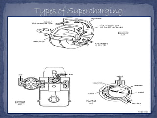
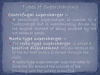
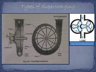
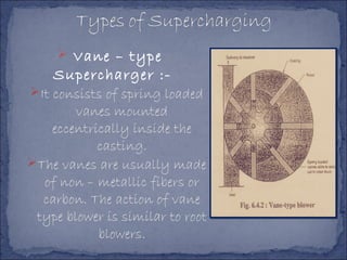
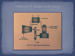
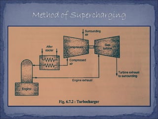
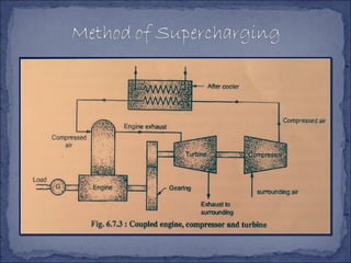


The document discusses different types of superchargers used to increase the power output of internal combustion engines. It describes supercharging as increasing the inlet air density to provide more air to the engine. There are three main types discussed: centrifugal superchargers which are mechanically driven; roots superchargers which use lobes to force air into the intake; and vane superchargers which use spring-loaded vanes. The document also covers four arrangements for driving superchargers: gear-driven from the engine; with an exhaust turbine; coupled engine and turbine; and gear-driven with a free turbine.


![Supercharging_and_Turbocharging_PPT_17_last_one[1].pptx](https://cdn.slidesharecdn.com/ss_thumbnails/superchargingandturbochargingppt17lastone1-231027120034-ab5f0e4e-thumbnail.jpg?width=640&height=640&fit=bounds)


