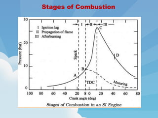
Combustion in an SI engine occurs in three stages:
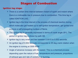
1. The ignition lag stage is the delay between the spark and noticeable pressure rise from combustion. This allows the fuel-air mixture to heat up to its self-ignition temperature.
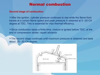
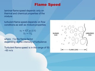
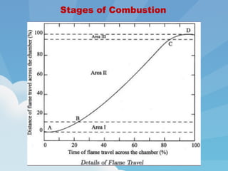
2. In the flame propagation stage, the flame front travels across the combustion chamber, releasing energy and increasing pressure.
3. The afterburning stage finishes combusting any remaining unburnt fuel-air mixture after the flame front passes.
Actual cycles for internal combustion engines differ from air-standard cycles in many respects.
Time loss factor.
Heat loss factor.
Exhaust blow down factor.
A gas turbine, also called a combustion turbine, is a type of internal combustion engine. It has an upstream rotating compressor coupled toa downstream turbine, and a combustion chamber in-between. Energy is added to the gas stream in the combustor, where fuel is mixed with air and ignited. In the high-pressure environment of the combustor, combustion of the fuel increases the temperature. The products of the combustion are forced into the turbine section
Visit https://www.topicsforseminar.com to Download
Theoretical cycle based on the actual properties of the cylinder contents is called the fuel air cycle.
The fuel air cycle takes into consideration the following.
The ACTUAL COMPOSITION of the cylinder contents.
The VARIATION OF SPECIFIC HEAT of the gases in the cylinder.
The DISSOCIATION EFFECT.
The VARIATION IN THE NUMBER OF MOLES present in the cylinder as the pressure and temperature change
PPT describes the engine performance parameters of the I.C. engine.
Engine performance is an indication of the degree of success of the engine performs its assigned task, i.e. the conversion of the chemical energy contained in the fuel into the useful mechanical work. The engine performance is indicated by the term efficiency, η. Five important engine efficiencies and other related engine performance parameters are:
Power
Indicated Thermal Efficiency (ηith)
Brake Thermal Efficiency (ηbth)
Mechanical Efficiency (ηm)
Volumetric Efficiency (ηv)
Relative Efficiency or Efficiency Ratio (ηrel)
Mean Effective Pressure (Pm)
Specific Fuel Consumption (sfc)
Fuel-Air or Air-Fuel Ratio (F/A or A/F)
Calorific Value (CV)
Power:-
The main purpose of running an engine is to obtain mechanical power.
Brake Power (B.P.)
The power developed by an Engine at the output shaft is called the brake power.
Brake Power= Brake Workdone/Time
B.P.=BWD/sec.
Indicated power (I.P.)
The total power developed by Combustion of fuel in the combustion chamber is called indicated power.
Indicated Power= Indicated Workdone/Time
I.P.=IWD/sec.
Frictional Power (F.P.)
The difference between I.P. and B.P. is called frictional power (f.p.).
FP = IP – BP
Thermal Efficiency (ηth)
Thermal efficiency is the ratio of Power to energy supplied by the fuel.
ηth= Power/ Energy
In I.C. Engine, thermal efficiency can be classified into two categories i.e.
Indicated Thermal Efficiency (ηith)
Indicated thermal efficiency is the ratio of indicated power to the heat supplied or added.
ηith= IP/Qs
2. Brake Thermal Efficiency (ηith)
Brake Thermal Efficiency is the ratio of brake power to the heat supplied or added.
ηbth= BP/Qs
Volumetric Efficiency (ηv)
This is one of the most important parameters which decide the performance of four-stroke engines. Four stoke engines have distinct suction stoke, volumetric efficiency indicates the breathing ability of the engine.
Volumetric efficiency is defined as the ratio of actual flow rate of air into the intake system to rate at which the volume is displaced by the system.
ηv= (푚 ̇"a/a" )/(푉푑푖푠푝푎푐푒푑 푋 푁/2)
"a"= Inlet density is taken atmospheric air density
N= Number of the cylinder in use
Definition of Supercharging ,
Effect of Supercharging ,
Need of Supercharging ,
Types of Supercharging
1) Centrifugal Supercharger
2) Rootes Supercharger
3) Vane Supercharger ,
Advantages & Disadvantages of Supercharging
A century and nearly two decades later there has been immense progress in the field of IC engines, though many phenomenon taking place are still to be understood physically. This blog aims at comprehension of some of the astonishing research that has been done in this field restricting our interest to combustion with some amusing facts.
Explain the operation of the various carburetor systems
Compare fuel injection to carburetion
Identify the different types of fuel injection
Describe the design and function of electronic fuel injection components
Understand how a computer feedback system works
Explain the operation of the various carburetor systems
Compare fuel injection to carburetion
Identify the different types of fuel injection
Describe the design and function of electronic fuel injection components
Understand how a computer feedback system works
Hierarchical Digital Twin of a Naval Power SystemKerry Sado
A hierarchical digital twin of a Naval DC power system has been developed and experimentally verified. Similar to other state-of-the-art digital twins, this technology creates a digital replica of the physical system executed in real-time or faster, which can modify hardware controls. However, its advantage stems from distributing computational efforts by utilizing a hierarchical structure composed of lower-level digital twin blocks and a higher-level system digital twin. Each digital twin block is associated with a physical subsystem of the hardware and communicates with a singular system digital twin, which creates a system-level response. By extracting information from each level of the hierarchy, power system controls of the hardware were reconfigured autonomously. This hierarchical digital twin development offers several advantages over other digital twins, particularly in the field of naval power systems. The hierarchical structure allows for greater computational efficiency and scalability while the ability to autonomously reconfigure hardware controls offers increased flexibility and responsiveness. The hierarchical decomposition and models utilized were well aligned with the physical twin, as indicated by the maximum deviations between the developed digital twin hierarchy and the hardware.
Cosmetic shop management system project report.pdfKamal Acharya
Buying new cosmetic products is difficult. It can even be scary for those who have sensitive skin and are prone to skin trouble. The information needed to alleviate this problem is on the back of each product, but it's thought to interpret those ingredient lists unless you have a background in chemistry.
Instead of buying and hoping for the best, we can use data science to help us predict which products may be good fits for us. It includes various function programs to do the above mentioned tasks.
Data file handling has been effectively used in the program.
The automated cosmetic shop management system should deal with the automation of general workflow and administration process of the shop. The main processes of the system focus on customer's request where the system is able to search the most appropriate products and deliver it to the customers. It should help the employees to quickly identify the list of cosmetic product that have reached the minimum quantity and also keep a track of expired date for each cosmetic product. It should help the employees to find the rack number in which the product is placed.It is also Faster and more efficient way.
Industrial Training at Shahjalal Fertilizer Company Limited (SFCL)MdTanvirMahtab2
This presentation is about the working procedure of Shahjalal Fertilizer Company Limited (SFCL). A Govt. owned Company of Bangladesh Chemical Industries Corporation under Ministry of Industries.
Final project report on grocery store management system..pdfKamal Acharya
In today’s fast-changing business environment, it’s extremely important to be able to respond to client needs in the most effective and timely manner. If your customers wish to see your business online and have instant access to your products or services.
Online Grocery Store is an e-commerce website, which retails various grocery products. This project allows viewing various products available enables registered users to purchase desired products instantly using Paytm, UPI payment processor (Instant Pay) and also can place order by using Cash on Delivery (Pay Later) option. This project provides an easy access to Administrators and Managers to view orders placed using Pay Later and Instant Pay options.
In order to develop an e-commerce website, a number of Technologies must be studied and understood. These include multi-tiered architecture, server and client-side scripting techniques, implementation technologies, programming language (such as PHP, HTML, CSS, JavaScript) and MySQL relational databases. This is a project with the objective to develop a basic website where a consumer is provided with a shopping cart website and also to know about the technologies used to develop such a website.
This document will discuss each of the underlying technologies to create and implement an e- commerce website.
About
Indigenized remote control interface card suitable for MAFI system CCR equipment. Compatible for IDM8000 CCR. Backplane mounted serial and TCP/Ethernet communication module for CCR remote access. IDM 8000 CCR remote control on serial and TCP protocol.
• Remote control: Parallel or serial interface.
• Compatible with MAFI CCR system.
• Compatible with IDM8000 CCR.
• Compatible with Backplane mount serial communication.
• Compatible with commercial and Defence aviation CCR system.
• Remote control system for accessing CCR and allied system over serial or TCP.
• Indigenized local Support/presence in India.
• Easy in configuration using DIP switches.
Technical Specifications
Indigenized remote control interface card suitable for MAFI system CCR equipment. Compatible for IDM8000 CCR. Backplane mounted serial and TCP/Ethernet communication module for CCR remote access. IDM 8000 CCR remote control on serial and TCP protocol.
Key Features
Indigenized remote control interface card suitable for MAFI system CCR equipment. Compatible for IDM8000 CCR. Backplane mounted serial and TCP/Ethernet communication module for CCR remote access. IDM 8000 CCR remote control on serial and TCP protocol.
• Remote control: Parallel or serial interface
• Compatible with MAFI CCR system
• Copatiable with IDM8000 CCR
• Compatible with Backplane mount serial communication.
• Compatible with commercial and Defence aviation CCR system.
• Remote control system for accessing CCR and allied system over serial or TCP.
• Indigenized local Support/presence in India.
Application
• Remote control: Parallel or serial interface.
• Compatible with MAFI CCR system.
• Compatible with IDM8000 CCR.
• Compatible with Backplane mount serial communication.
• Compatible with commercial and Defence aviation CCR system.
• Remote control system for accessing CCR and allied system over serial or TCP.
• Indigenized local Support/presence in India.
• Easy in configuration using DIP switches.
NO1 Uk best vashikaran specialist in delhi vashikaran baba near me online vas...Amil Baba Dawood bangali
Contact with Dawood Bhai Just call on +92322-6382012 and we'll help you. We'll solve all your problems within 12 to 24 hours and with 101% guarantee and with astrology systematic. If you want to take any personal or professional advice then also you can call us on +92322-6382012 , ONLINE LOVE PROBLEM & Other all types of Daily Life Problem's.Then CALL or WHATSAPP us on +92322-6382012 and Get all these problems solutions here by Amil Baba DAWOOD BANGALI
#vashikaranspecialist #astrologer #palmistry #amliyaat #taweez #manpasandshadi #horoscope #spiritual #lovelife #lovespell #marriagespell#aamilbabainpakistan #amilbabainkarachi #powerfullblackmagicspell #kalajadumantarspecialist #realamilbaba #AmilbabainPakistan #astrologerincanada #astrologerindubai #lovespellsmaster #kalajaduspecialist #lovespellsthatwork #aamilbabainlahore#blackmagicformarriage #aamilbaba #kalajadu #kalailam #taweez #wazifaexpert #jadumantar #vashikaranspecialist #astrologer #palmistry #amliyaat #taweez #manpasandshadi #horoscope #spiritual #lovelife #lovespell #marriagespell#aamilbabainpakistan #amilbabainkarachi #powerfullblackmagicspell #kalajadumantarspecialist #realamilbaba #AmilbabainPakistan #astrologerincanada #astrologerindubai #lovespellsmaster #kalajaduspecialist #lovespellsthatwork #aamilbabainlahore #blackmagicforlove #blackmagicformarriage #aamilbaba #kalajadu #kalailam #taweez #wazifaexpert #jadumantar #vashikaranspecialist #astrologer #palmistry #amliyaat #taweez #manpasandshadi #horoscope #spiritual #lovelife #lovespell #marriagespell#aamilbabainpakistan #amilbabainkarachi #powerfullblackmagicspell #kalajadumantarspecialist #realamilbaba #AmilbabainPakistan #astrologerincanada #astrologerindubai #lovespellsmaster #kalajaduspecialist #lovespellsthatwork #aamilbabainlahore #Amilbabainuk #amilbabainspain #amilbabaindubai #Amilbabainnorway #amilbabainkrachi #amilbabainlahore #amilbabaingujranwalan #amilbabainislamabad
Hybrid optimization of pumped hydro system and solar- Engr. Abdul-Azeez.pdffxintegritypublishin
Advancements in technology unveil a myriad of electrical and electronic breakthroughs geared towards efficiently harnessing limited resources to meet human energy demands. The optimization of hybrid solar PV panels and pumped hydro energy supply systems plays a pivotal role in utilizing natural resources effectively. This initiative not only benefits humanity but also fosters environmental sustainability. The study investigated the design optimization of these hybrid systems, focusing on understanding solar radiation patterns, identifying geographical influences on solar radiation, formulating a mathematical model for system optimization, and determining the optimal configuration of PV panels and pumped hydro storage. Through a comparative analysis approach and eight weeks of data collection, the study addressed key research questions related to solar radiation patterns and optimal system design. The findings highlighted regions with heightened solar radiation levels, showcasing substantial potential for power generation and emphasizing the system's efficiency. Optimizing system design significantly boosted power generation, promoted renewable energy utilization, and enhanced energy storage capacity. The study underscored the benefits of optimizing hybrid solar PV panels and pumped hydro energy supply systems for sustainable energy usage. Optimizing the design of solar PV panels and pumped hydro energy supply systems as examined across diverse climatic conditions in a developing country, not only enhances power generation but also improves the integration of renewable energy sources and boosts energy storage capacities, particularly beneficial for less economically prosperous regions. Additionally, the study provides valuable insights for advancing energy research in economically viable areas. Recommendations included conducting site-specific assessments, utilizing advanced modeling tools, implementing regular maintenance protocols, and enhancing communication among system components.
Hybrid optimization of pumped hydro system and solar- Engr. Abdul-Azeez.pdf
Combustion in si engine
1. Combustion in SI engineCombustion in SI engine
Engine combustion and
Pollution Control
2. Introduction
In a conventional SI engine, fuel and air are mixed together in the intake
system, inducted through the intake valve into the cylinder where mixing with
residual gas takes place, and then compressed during the compression stroke.
Under normal operating conditions, combustion is initiated towards the end of
compression stroke at the spark plug by an electric discharge.
Following inflammation, a turbulent flame develops, propagates through the
premixed air-fuel mixture (and burned gas mixture from the previous cycle)
until it reaches combustion chamber walls, then it extinguishes.
7. Combustion may be defined as a relatively rapid chemical combination of
hydrogen and carbon in fuel with oxygen in air resulting in liberation of
energy in the form of heat.
Following conditions are necessary for combustion to take place
1. The presence of combustible mixture
2. Some means to initiate mixture
3. Stabilization and propagation of flame in Combustion Chamber
In S I Engines, carburetor supplies a combustible mixture of petrol and air
and spark plug initiates combustion
Combustion
8. Combustion
Combustion event must be properly located relative to the TDC to obtain max
power or torque.
Combined duration of the flame development and propagation process is
typically between 30 and 90 CA degrees.
If the start of combustion process is progressively advanced before TDC,
compression stroke work transfer (from piston to cylinder gases) increases.
If the end of combustion process is progressively delayed by retarding the
spark timing, peak cylinder pressure occurs later in the expansion stroke and
is reduced in magnitude.
These changes reduce the expansion stroke work transfer from cylinder
gases to the piston.
The optimum timing which gives maximum brake torque (called maximum
brake torque or MBT timing) occurs when magnitude of these two opposing
trends just offset each other.
9. Combustion
Timing which is advanced or retarded from this optimum MBT timing
gives lower torque.
Optimum spark setting will depend on the rate of flame development
and propagation, length of flame travel path across the combustion
chamber, and details of the flame termination process after it reaches
the wall -these depend on engine design, operating conditions and
properties of the fuel-air and burned gas mixture.
With optimum spark setting, max pressure occurs at about 15 degrees
CA after TDC (10 -15), half the charge is burned at about 10 degrees
CA after TDC.
In practice spark is retarded to give a 1 or 2 % reduction in brake
torque from max value, to permit a more precise definition of the
timing relative to the optimum.
10. Combustion
Normal combustion
spark-ignited flame moves steadily across the combustion
chamber until the charge is fully consumed.
Abnormal combustion
fuel composition, engine design and operating parameters,
combustion chamber deposits may prevent occurring of the
normal combustion process.
There are two types of abnormal combustion :
Knock
Surface ignition
11. Normal combustion
When piston approaches the end of compression stroke, a spark is
discharged between the spark plug electrodes –spark produces a
small nucleus of flame that propagates into unburnt gas.
There is a delay of approx constant duration until a noticable increase
in the cylinder pressure as a result of chemical reactions is recorded
in “p ~ α diagram” -called the delay period.
This is approx 0.5 ms (for example corresponds to 7.5 OCA at 2500
rpm) and only approx 1 % of the charge is burned during that period.
Delay period depends on temperature, pressure and composition of
fuel-air mixture, the energy applied at the spark plug, the duration of
the spark, volume of the charge which is ignited initially and the gas
flow in the cylinder (turbulence level).
12. Normal combustion
Second stage of combustion
After the ignition, cylinder pressure continues to rise while the flame front
travels at a certain flame speed and peak pressure is obtained at 5 –20 CA
degree at TDC. This is essential for max thermal efficiency.
Since combustion takes a finite time, mixture is ignited before TDC, at the
end of compression stroke –spark advance
The second stage continues until maximum pressure is obtained and lasts
about 25 –30 CA degree.
13. Knock
Knock is the auto-ignition of the portion of fuel, air and residual gas
mixture ahead of the advancing flame, that produces a noise.
As the flame propagates across combustion chamber, end gas is
compressed causing pressure, temperature and density to
increase. Some of the end gas fuel-air mixture may undergo
chemical reactions before normal combustion causing auto-ignition
-end gases then burn very rapidly releasing energy at a rate 5 to 25
times in comparison to normal combustion. This causes high
frequency pressure oscillations inside the cylinder that produce
sharp metallic noise called knock.
Knock will not occur when the flame front consumes the end gas
before these reactions have time to cause fuel-air mixture to auto-
ignite. Knock will occur if the pre-combustion reactions produce
auto-ignition before the flame front arrives.
18. Surface Ignition
Surface ignition is ignition of the fuel-air charge by overheated
valves or spark plugs, by glowing combustion chamber
deposits or by any other hot spot in the engine combustion
chamber -it is ignition by any source other than the spark plug.
It may occur before the spark plug ignites the charge (pre-
ignition) or after normal ignition (post-ignition).
It may produce a single flame or many flames.
Surface ignition may result in knock.
19. Flame Flow
Combustion process takes place in a turbulent flow field.
The structure of the flame and the speed at which it propagates
across the combustion chamber depends on charge motion,
charge composition and combustion chamber geometry –engine
design, operating conditions and mixture properties.
The volume enflamed behind the flame front continues to grow in
roughly spherical manner, except where intersected by the
chamber walls.
At any flame radius and engine geometry, flame front surface
area influences combustion –larger this surface area, the greater
the mass of fresh charge that cross this surface and enter the
flame zone.
20. Flame speed
Laminar flame speed is the velocity at which the flame propagates into
inactive premixed unburnt mixture ahead of the flame.
Flame is the result of a self sustaining chemical reaction occurring within
a region of space called the flame front where unburnt mixture is heated
and converted into products. Flame front consists of two regions; a
preheat zone (temperature of the unburnt mixture is raised mainly by heat
conduction from the reaction zone, no significant reaction takes place)
and a reaction zone (upon reaching a critical temperature exothermic
chemical reaction begins -the temperature where exothermic reaction
begins to the hot boundary at downstream equilibrium burned gas
temperature).
21. Turbulent and laminar
Flame Speed
Turbulent flames are characterized by the root mean square velocity
fluctuations, the turbulence intensity u’ rms and various length scales of
turbulent flow ahead of the flame.
Integral length scale, lI is a measure of the size of large energy-containing
structures of the flow.
Kolmogorov scale, lK defines the smallest structures of the flow where small-
scale kinetic energy is dissipated by molecular viscosity.
Laminar flame thickness, is given as the molecular diffusivity over the
laminar flame speed
25. Final Stage of Combustion
Final stage covers the period from the max cylinder pressure to
the termination of the combustion process.
Maximum temperature value is reached during this stage (after
max p)
Usually 70 –75% of the total energy is released until max p is
obtained, and 85 –90% of the total energy is released until max
T is obtained.
For partial load conditions, the flame speed is lower (low T and
p), only 50 % of the energy is released until max pressure point.
26. Ignition Limits
Ignition of charge is only possible within certain limits of fuel-air ratio. Ignition
limits correspond approximately to those mixture ratios, at lean and rich ends
of scale, where heat released by spark is no longer sufficient to initiate
combustion in neighboring unburnt mixture. For hydrocarbons fuel the
stoichiometric fuel air ratio is 1:15 and hence the fuel air ratio must be about
1:30 and 1:7
27. Theories of Combustion In SI Engine
Combustion in SI engine may roughly
divided into two general types:
Normal and Abnormal (knock free or
Knocking). (a-b) is compression process, (b-
c) is combustion process and (c-d) is an
expansion process. In an ideal cycle it can be
seen from the diagram, the entire pressure
rise during combustion takes place at
constant volume i.e., at TDC. However, in
actual cycle this does not happen.
Theoretical diagram of pressure crank
angle diagram
33. Ignition lag stage:
There is a certain time interval between instant of spark and instant where
there is a noticeable rise in pressure due to combustion. This time lag is
called IGNITION LAG.
Ignition lag is the time interval in the process of chemical reaction during
which molecules get heated up to self ignition temperature, get ignited and
produce a self propagating nucleus of flame.
The ignition lag is generally expressed in terms of crank angle (Ө1). The
period of ignition lag is shown by path AB.
Ignition lag is very small and lies between 0.0015 to 0.002 seconds.
An ignition lag of 0.002 seconds corresponds to 35 deg crank rotation when
the engine is running at 3000 RPM.
Angle of advance increase with the speed. This is a chemical process
depending upon the nature of fuel, temperature and pressure, proportions
of exhaust gas and rate of oxidation or burning.
Stages of Combustion
34. Stages of Combustion
Flame propagation stage:
Once the flame is formed at “B”, it should be self sustained and must be able
to propagate through the mixture. This is possible when the rate of heat
generation by burning is greater than heat lost by flame to surrounding. After
the point “B”, the flame propagation is abnormally low compared at the
beginning as heat lost is more than heat generated. Therefore pressure rise is
also slow as mass of mixture burned is small. Therefore it is necessary to
provide angle of advance 30 to 35 deg, if the peak pressure to be attained 5-
10 deg after TDC. The time required for crank to rotate through an angle Ө2 is
known as combustion period during which propagation of flame takes place.
35. After burning:
Combustion will not stop at point “C” but continue after attaining peak
pressure and this combustion is known as after burning. This generally
happens when the rich mixture is supplied to engine.
Stages of Combustion
36. Factors Affecting the Flame Propagation
Rate of flame propagation affects the combustion process in SI engines. Higher
combustion efficiency and fuel economy can be achieved by higher flame
propagation velocities. Unfortunately flame velocities for most of fuel range
between 10 to 30 m/second.
The factors which affect the flame propagations are
Air fuel ratio
Temperature and pressure
Compression ratio
Load on engine
Turbulence
Engine speed
Engine size
Other factors
37. Factors Affecting the Flame Propagation
A : F ratio.
Mixture strength influences the rate of combustion and amount of heat
generated.
Maximum flame speed for all hydrocarbon fuels occurs at nearly 10% rich
mixture.
Flame speed is reduced both for lean and as well as for very rich mixture.
Lean mixture releases less heat resulting lower flame temperature and
lower flame speed.
Very rich mixture results incomplete combustion, results in production of
less heat and flame speed remains low.
38. Indicator diagram for stoichiometric and weak mixture
The effects of A: F ratio on p-v
diagram and p-Ө diagram are
shown below :.
39. A : F ratio.
Factors Affecting the Flame Propagation
41. Factors Affecting the Flame Propagation
Temperature and Pressure:
Flame speed increases with an increase in intake temperature
and pressure.
A higher initial pressure and temperature may help to form a
better homogeneous air-vapor mixture which helps in
increasing the flame speed. This is possible because of an
overall inert in the density of the charge.
42. Compression ratio:
Higher compression ratio increases the pressure and temperature of the
mixture and also decreases the concentration of residual gases.
All these factors reduce the ignition lag and help to speed up the second
phase of combustion.
The maximum pressure of the cycle as well as mean effective pressure of
the cycle increase with increase in compression ratio.
Higher compression ratio increases the surface to volume ratio and
thereby increases the part of the mixture which after-burns in the third
phase.
Factors Affecting the Flame Propagation
43. Factors Affecting the Flame Propagation
Effect of compression ratio on pressure (indirectly on the speed of combustion)
with respect to crank angle for same A: F ratio and same angle of advance
44. Load on Engine.
With increase in load, the cycle pressures increase and the flame speed
also increases. In S.I. engine, the power developed by an engine is
controlled by throttling. At lower load and higher throttle, the initial and final
pressure of the mixture after compression decrease and mixture is also
diluted by the more residual gases. This reduces the flame propagation and
prolongs the ignition lag. This is the reason, the advance mechanism is also
provided with change in load on the engine. This difficulty can be partly
overcome by providing rich mixture at part loads but this definitely increases
the chances of afterburning. The after burning is prolonged with richer
mixture. In fact, poor combustion at part loads and necessity of providing
richer mixture are the main disadvantages of SI engines which causes
wastage of fuel and discharge of large amount of CO with exhaust gases.
Factors Affecting the Flame Propagation
45. Turbulence :
Flame speed is directly proportional to the turbulence of the mixture. This is
because, the turbulence increases the mixing and heat transfer coefficient or
heat transfer rate between the burned and unburned mixture. The turbulence
of the mixture can be increased at the end of compression by suitable design
of the combustion chamber (geometry of cylinder head and piston crown).
Insufficient turbulence provides low flame velocity and incomplete combustion
and reduces the power output.
Excessive turbulence is also not desirable as it increases the combustion
rapidly and leads to detonation. Excessive turbulence causes to cool the
flame generated and flame propagation is reduced.
Moderate turbulence is always desirable as it accelerates the chemical
reaction, reduces ignition lag, increases flame propagation and even allows
weak mixture to burn efficiently.
Factors Affecting the Flame Propagation
46. Engine Speed
The turbulence of the mixture increases with an increase in engine speed. For
this reason the flame speed almost increases linearly with engine speed. If the
engine speed is doubled, time to traverse the combustion chamber is halved.
Double the original speed and half the original time give the same number of
crank degrees for flame propagation. The crank angle required for the flame
propagation, which is main phase of combustion will remain almost constant at
all speeds. This is an important characteristics of all petrol engines.
Increases of the engine speed, reduces the time available for a complete
combustion.
Increases in engine speed also increases the mean piston speed and turbulence
intensity-increases flame speed. But this doesn’t effect the ignition delay period,
thus delay period increases in CA degrees.
To compensate this, ignition timing should adjusted-spark advance is increased
with increasing engine speed.
Factors Affecting the Flame Propagation
47. Factors Affecting the Flame Propagation
Engine Size
Engines of similar design generally run at the same piston speed. This is
achieved by using small engines having larger RPM and larger engines
having smaller RPM. Due to same piston speed, the inlet velocity, degree of
turbulence and flame speed are nearly same in similar engines regardless of
the size. However, in small engines the flame travel is small and in large
engines large. Therefore, if the engine size is doubled the time required for
propagation of flame through combustion space is also doubled. But with
lower RPM of large engines the time for flame propagation in terms of crank
would be nearly same as in small engines. In other words, the number of
crank degrees required for flame travel will be about the same irrespective of
engine size provided the engines are similar.
48. Factors Affecting the Flame Propagation
Other Factors.
Among the other factors, the factors which increase the flame speed are
supercharging of the engine, spark timing and residual gases left in the
engine at the end of exhaust stroke. The air humidity also affects the
flame velocity but its exact effect is not known. Anyhow, its effect is not
large compared with A :F ratio and turbulence.
49. Phenomenon of knock in SI engines
In a spark-ignition engine combustion is initiated between the spark plug
electrodes spreads across the combustible mixture. A definite flame front
separates the fresh mixture from the products of combustion travels from the
spark plug to the other end of the combustion chamber.
Heat release due to combustion increases the temperature and consequently
the pressure, of the burned part of the mixture above those of the unburned
mixture. In order to effect pressure equalization the burned part of the mixture
will expand, and compress the unburned mixture adiabatically thereby
increasing its pressure and temperature. This process continues as the flame
front advances through the mixture and the temperature and pressure of the
unburned mixture are increased further.
If the temperature of the unburnt mixture exceeds the self-ignition
temperature of the fuel and remains at or above this temperature during the
period of pre-flame reactions (ignition lag), spontaneous ignition or auto
ignition occurs at various pin-point locations. This phenomenon is called
knocking. The process of auto ignition leads towards engine knock.
50. This phenomenon of knock may be explained by referring the figures which shows
the cross-section of the combustion chamber with flame advancing from the spark
plug location with and without knock.
Normal Combustion
In the normal combustion the flame travels across the combustion chamber
from A towards D. The advancing flame front compresses the end charge BB'D
farthest from the spark plug thus raising its temperature. The temperature is
also increased due to heat transfer from the hot advancing flame-front. Also
some pre-flame oxidation may take place in the end charge leading to further
increase in temperature. In spite of these factors if the temperature of the end
charge had not reached its self-ignition temperature, the charge would not auto
ignite and the flame will advance further and consume the charge BB‘D. This is
the normal combustion process which is illustrated by means of the pressure-
time diagram.
Phenomenon of knock in SI engines
51. Phenomenon of knock in SI engines
Abnormal Combustion
However, if the end charge BB'D reaches its auto ignition temperature and
remains for some length of time equal to the time of pre-flame reactions the
charge will auto ignite, leading to knocking combustion. it is assumed that
when flame has reached the position BB', the charge ahead of it has reached
critical auto ignition temperature. During the pre-flame reaction period if the
flame front could move from BB' to only CC’ then the charge ahead of CC'
would auto ignite.
Combustion with Detonation
52. Because of the auto-ignition, another flame front starts traveling in the
opposite direction to the main flame front. When the two flame fronts collide,
a severe pressure pulse is generated. The gas in the chamber is subjected to
compression and rarefaction along the pressure pulse until pressure
equilibrium is restored. This disturbance can force the walls of the
combustion chambers to vibrate at the same frequency as the gas. Gas
vibration frequency in automobile engines is of the order of 5000 cps. The
pressure-time trace of such a situation is shown.
It is to be noted that the onset of knocking is very much dependent on the
properties of fuel. It is clear from the above description that if the unburned
charge does not reach its auto-ignition temperature there will be no knocking.
Further, if the initial phase i.e., ignition lag period, is longer than the time
required for the flame front to burn through the unburned charge, there will be
no knocking. But, if the critical temperature is reached and maintained, and
the ignition lag is shorter than the time it takes for the flame front to burn
through the unburned charge then the end charge will detonate. Hence, in
order to avoid or inhibit detonation, a high auto-ignition temperature and a
long ignition lag are the desirable qualities for SI engine fuels.
Phenomenon of knock in SI engines
53. In summary, when auto-ignition occurs, two different types of vibration
may be produced. In one case a large amount of mixture may auto-
ignite giving rise to a very rapid increase in pressure throughout the
combustion chamber and there will be a direct blow on the engine
structure. The human ear can detect the resulting thudding sound and
consequent noise from free vibrations of the engine parts. In the other
case, large pressure differences may exist in the combustion chamber
and the resulting gas vibrations can force the walls of the chamber to
vibrate at the same frequency as the gas. An audible sound may be
evident.
The impact of knock on the engine components and structure can
cause engine failure and in addition the noise from engine vibration is
always objectionable.
The pressure differences in the combustion chamber cause the gas to
vibrate and scrub the chamber walls causing increased loss of heat to
the coolant.
Phenomenon of knock in SI engines
54. Effect of engine variables on knock
Any factor which reduces the density of the charge tends to reduce knocking by
providing lower energy release.
Compression Ratio:
Compression ratio determines both the pressure and temperature at the
beginning of the combustion process. Increase in compression ratio increases
the pressure and temperature of the gases at the end of the compression
stroke. This decreases the ignition lag of the end gas and thereby increasing
the tendency for knocking. The overall increase in the density of the charge
due to higher compression ratio increases the pre-flame reactions in the end
charge thereby increasing the knocking tendency of the engine. The increase
in the knocking tendency of the engine with increasing compression ratio is the
main reason for limiting the compression ratio to a lower value.
Mass of Inducted Charge:
A reduction in the mass of the inducted charge into the cylinder of an engine by
throttling or by reducing the amount of supercharging reduces both
temperature and density of the charge at the time of ignition. This decreases
the tendency of knocking.
55. Effect of engine variables on knock
Inlet Temperature of the Mixture:
Increase in the inlet temperature of the mixture makes the
compression temperature higher thereby, increasing the tendency of
knocking. Further, volumetric efficiency will be lowered. Hence a lower
inlet temperature is always preferable to reduce knocking. It is
important that the temperature should not be so low as to cause
starting and vaporization problems in the engine.
Temperature of the Combustion Chamber Walls:
Temperature of the combustion chamber walls play a predominant role
in knocking. In order to prevent knocking the hot spots in the
combustion chamber should be avoided. Since, the spark plug and
exhaust valve are two hottest parts in the combustion chamber, the
end gas should not be compressed against them.
56. Effect of engine variables on knock
Retarding the Spark Timing:
By retarding the spark timing from the optimized timing, i.e.,
having the spark closer to TDC, the peak pressures are
reached farther down on the power stroke and are thus of
lower magnitude. This might reduce the knocking. However,
this will affect the brake torque and power output of the engine.
Power Output of the Engine:
A decrease in the output of the engine decreases the
temperature of the cylinder and the combustion chamber walls
and also the pressure of the charge thereby lowering mixture
and end gas temperatures. This reduces the tendency to
knock.
57. Effect of engine variables on knock
Increasing the flame speed or increasing the duration of the ignition lag or reducing
the time of exposure of the unburned mixture to auto-ignition condition will tend to
reduce knocking.
Turbulence:
Turbulence depends on the design of the combustion chamber and on engine
speed. Increasing turbulence increases the flame speed and reduces the time
available for the end charge to attain auto-ignition conditions thereby decreasing
the tendency to knock.
Engine Speed:
An increase in engine speed increases the turbulence of the mixture
considerably resulting in increased flame speed, and reduces the time available
for pre-flame reactions. Hence knocking tendency is reduced at higher speeds.
Flame Travel Distance:
The knocking tendency is reduced by shortening the time required for the flame
front to traverse the combustion chamber. Engine size (combustion chamber
size), and spark plug position are the three important factors governing the
flame travel distance.
58. Effect of engine variables on knock
Engine Size:
The flame requires a longer time to travel across the combustion chamber of a
larger engine. Therefore, a larger engine has a greater tendency for knocking
than a smaller engine since there is more time for the end gas to auto-ignite.
Hence, an SI engine is generally limited to size of about 150 mm bore.
Combustion Chamber Shape:
Generally, the more compact the combustion chamber is, the shorter is the
flame travel and the combustion time and hence better antiknock
characteristics. Therefore, the combustion chambers are made as spherical as
possible to minimize the length of the flame travel for a given volume. If the
turbulence in the combustion chamber is high, the combustion rate is high and
consequently combustion time and knocking tendency are reduced. Hence, the
combustion chamber is shaped in such a way as to promote turbulence.
Location of Spark Plug:
In order to have a minimum flame travel the spark plug is centrally located in
the combustion chamber, resulting in minimum knocking tendency. The flame
travel can also be reduced by using two or more spark plugs in case of large
engines.
59. Effect of engine variables on knock
Once the basic design of the engine is finalized, the fuel-air ratio and properties of
the fuel, particularly the octane rating, play a crucial role in controlling the knock.
Fuel-Air Ratio:
The flame speeds are affected by fuel-air ratio. Also the flame temperature and
reaction time are different for different fuel-air ratios. Maximum flame
temperature is obtained when Ø ≡ 1.1 to I.2 whereas Ø = 1 gives minimum
reaction time for auto-ignition.
Figure below shows the variation of knock limited compression ratio with respect
to equivalence ratio for iso-octane. The maximum tendency to knock takes place
for the fuel-air ratio which gives minimum reaction time.
60. Effect of engine variables on knock
Octane Value of the Fuel:
A higher self-ignition temperature of the fuel and a low pre-flame
reactivity would reduce the tendency of knocking.
In general paraffin series of hydrocarbon have the maximum and
aromatic series the minimum tendency to knock & the naphthene series
comes in between the two.
Usually, compounds with more compact molecular structure are less
prone to knock. In aliphatic hydrocarbons, unsaturated compounds show
lesser knocking tendency than saturated hydrocarbons, the exception
being ethylene, acetylene and propylene.
61. Combustion Chamber Design
The design of the combustion chamber for an SI engine has an
important influence on the engine performance and its knocking
tendencies.
Combustion chambers that provide a minimal tendency to knock
must satisfy the following basic requirements:
a) Short flame travel, thus a compact combustion chamber and
central position of spark plug
b) Avoid hot spots at the end of the flame travel, spark plugs
should be located near the hottest spots (exhaust valves)
c) High flow velocities in combustion chamber through swirl
or tumble movements (turbulence) as well as squish-induced
flows at the end of compression, to increase the flame velocity.
62. Combustion Chamber Design
The design involves the shape of the combustion chamber, the location of
spark plug and the location of inlet and exhaust valves.
Combustion chambers must be designed carefully, keeping in mind the
following general objectives.
Smooth Engine Operation
The aim of engine design is to have a smooth operation and a good economy.
These can be achieved by the following:
Moderate rate of pressure rise:
The rate of pressure rise can be regulated such that the greatest force is
applied to the piston as closely after TDC on the power stroke as
possible, with a gradual decrease in the force on the piston during the
power stroke. The forces must be applied to the piston smoothly, thus
limiting the rate of pressure rise as well as the position of the peak
pressure with respect to TDC.
Reducing the Possibility of Knocking:
Reduction in the possibility of knocking, in an engine can be achieved by,
Reducing the distance of the flame travel by centrally locating the spark
plug and also by avoiding pockets of stagnant charge
63. Combustion Chamber Design
Satisfactory cooling of the spark plug and of exhaust valve area which are the
source of hot spots in the majority of the combustion chambers.
Reducing the temperature of the last portion of the charge, through application of a
high surface to volume ratio in that part where the last portion of the charge burns.
Heat transfer to the combustion chamber walls can be increased by using high
surface to volume ratio thereby reducing the temperature.
64. Combustion Chamber Design
High Power Output and Thermal Efficiency
The main objective of the design and development of an engine is to obtain
high power as well as high thermal efficiency. This can be achieved by
considering the following factors:
A high degree of turbulence is needed to achieve a high flame front velocity.
Turbulence is induced by inlet flow configuration or squish. Squish can be
induced in spark-ignition engines by having a bowl in piston or with a dome
shaped cylinder head. Squish is the rapid radial movement of the gas
trapped in between the piston and the cylinder head into the bowl or the
dome.
High volumetric efficiency, i.e., more charge during the suction stroke,
results in an increased power output. This can be achieved by providing
ample clearance around the valve heads, large diameter valves and straight
passages with minimum pressure drop.
Any design of the combustion chamber that improves its antiknock
characteristics permits the use of a higher compression ratio resulting in
increased output and efficiency.
A compact combustion chamber reduces heat loss during combustion and
increases the thermal efficiency.
65. Combustion Chambers Types
Different types of combustion chambers have been developed over a period of
time.
T-Head Type:
This was first introduced by Ford Motor Corporation
Disadvantages
Requires two cam shafts (for actuating the in-let valve and exhaust
valve separately) by two cams mounted on the two cam shafts.
Very prone to detonation. There was violent detonation even at a
compression ratio of 4.
T-Head Type:
L-Head Type
66. Combustion Chambers Types
L-Head Type:
This was first introduced by Ford motor and was quite popular for some time.
A modification of the T-head type of combustion chamber is the L-head type
which provides the two valves on the same side of the cylinder and the valves
are operated by a single camshaft.
Advantages
Valve mechanism is simple and easy to lubricate.
Detachable head easy to remove for cleaning and decarburizing without
disturbing either the valve gear or main pipe work.
Valves of larger sizes can be provided.
Disadvantages
Lack of turbulence.
Extremely prone to detonation due to large flame length and slow combustion
due to lack of turbulence.
More surface-to-volume ratio and therefore more heat loss.
Extremely sensitive to ignition timing due to slow combustion process.
Thermal failure in cylinder block also.
68. Combustion Chambers Types
Ricardo’s Turbulent Head-Side Valve Combustion
Chamber
Ricardo developed this head in 1919.
Main objective was to obtain fast flame speed and reduce knock in L design.
In Ricardo’s design the main body of combustion chamber was concentrated over the
valves, leaving slightly restricted passage communicating with cylinder.
Advantages
Additional turbulence during compression stroke is possible as gases are forced
back through the passage.
By varying throat area of passage designed, degree of additional turbulence is
possible.
Ensures a more homogeneous mixture by scoring away the layer of stagnant
gas clinging to chamber wall. Both the above factors increase the flame speed
and thus the performance.
Deign make engine relatively insensitive to timing of spark due to fast
combustion
Higher engine speed is possible due to increased turbulence
Ricardo’s design reduced the tendency to knock by shortening length of
effective flame travel by bringing that portion of head which lay over the further
side of piston into as close a contact as possible with piston crown.
This design reduces length of flame travel by placing the spark plug in the
69. Combustion Chambers Types
Disadvantages
With compression ratio of 6, normal speed of burning increases and turbulent
head tends to become over turbulent and rate of pressure rise becomes too rapid
leads to rough running and high heat losses. To overcome the above problem,
Ricardo decreased the areas of passage at the expense of reducing the clearance
volume and restricting the size of valves. This reduced breathing capacity of
engine, therefore these types of chambers are not suitable for engine with high
compression ratio.
Ricardo’s Turbulent Head-Side Valve Combustion
Chamber
70. Combustion Chambers Types
Over head valve or I head combustion
chamber
This type of combustion chamber has both the inlet valve and the exhaust
valve located in the cylinder head.
An overhead engine is superior to side valve engine at high compression
ratios.
Advantages
Lower pumping losses and higher volumetric efficiency from better breathing
of the engine from larger valves or valve lifts and more direct passageways.
Less distance for the flame to travel and therefore greater freedom from
knock, or in other words, lower octane requirements.
Less force on the head bolts and therefore less possibility of leakage (of
compression gases or jacket water). The projected area of a side valve
combustion chamber is inevitably greater than that of an overhead valve
chamber.
Removal of the hot exhaust valve from the block to the head, thus confining
heat failures to the head. Absence of exhaust valve from block also results in
more uniform cooling of cylinder and piston.
Lower surface-volume ratio and, therefore, less heat loss and less air
pollution.
Easier to cast and hence lower casting cost.
72. Combustion Chambers Types
F- Head combustion chamber
In such a combustion chamber one valve is in head and other in the
block.
This design is a compromise between L-head and I-head combustion
chambers.
One of the most F-head engines (wedge type) is the one used by the
Rover Company for several years.
Another successful design of this type of chamber is that used in
Willeys jeeps.
Advantages
High volumetric efficiency
Maximum compression ratio for fuel of given octane rating
High thermal efficiency
It can operate on leaner air-fuel ratios without misfiring.
Disadvantages
This design is the complex mechanism for operation of valves and
expensive special shaped piston.