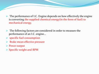
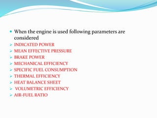
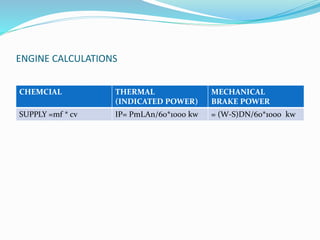
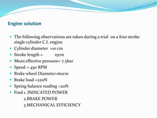
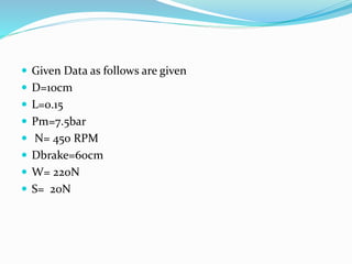
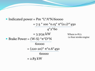
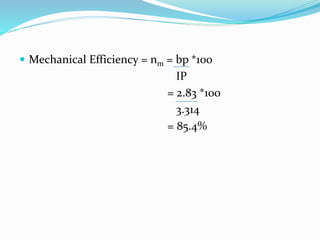
SlideShare a Scribd company logo
1 of 26
PERFORMANCE TESTING OF IC
ENGINE
BY
INDRAKUMAR R PADWANI
BE MECHANICAL,MBA MARKETING PGDCA
LECTURER IN MECHANICAL ENGG DEPT
GOVERNMENT POLYTECHNIC GODHRA
GODHRA.GUJARAT
 The performance of I.C. Engine depends on how effectively the engine
is converting the supplied chemical energy(in the form of fuel) to
mechanical energy.
 The following factors are considered in order to measure the
performance of an I.C. engine…
 specific fuel consumption
 Brake mean effective pressure
 Power output
 Specific weight and RPM
 When the engine is used following parameters are
considered
 INDICATED POWER
 MEAN EFFECTIVE PRESSURE
 BRAKE POWER
 MECHANICAL EFFICIENCY
 SPECIFIC FUEL CONSUMPTION
 THERMAL EFFICIENCY
 HEAT BALANCE SHEET
 VOLUMETRIC EFFICIENCY
 AIR-FUEL RATIO
INDICATED POWER
 The total power developed by combustion chamber of an engine is known
as Indicated power
 This power is the power produced in the cylinder.
 Equation to calculate Indicated power
 Pm=Indicated Mean effective pressure N/m
 A= Cross –sectional Area of piston m

 where Dp = Diameter of piston m
 L= length of stroke m
 n =Number of power stroke/minute
 n(For two stroke engine )
 n/2 ( for four stroke engine )
 N= Speed of the engine RPM

Force on piston = Pm * A --------- newton
Work done/cycle= (Pm*A) L---------N-m
Therefore indicated power = Pm * A *L *N N.m/min
Pm *A*L*n/60 N.m/sec or J/sec
or w
PmLAn/60*1000 kw
This is for single cylinder engine.
For multi cylinder engine..
indicated power=PmLAn/60000 *K KW
where K= Number of cylinders…
 BRAKE POWER (bp)
 The brake power of an I.C. engine is the power available at the
crankshaft
 .Power developed by the engine at the output shaft.The brake
power of an I.C. engine is usually measured by means of an brake
mechanism (prony brake or Rope brake ).The break power of an
engine is always less than indicated power.
 Brake Rope dynamometer:-
 In brake rope type of dynamometer,rope is wound on the brake
drum.The brake drum is placed on the crankshaft.One end of
the rope is attached with spring balance and other one is
attached with the pan on which loads can be placed.The load is
given on the engine.Then spring balance (S) is taken and it is
noted down. The diameter of drum rope and R.P.M during
testing are noted down.
 Let D1= Diameter of brake pulley m
 d1=DSiameter of Rope m
 D = Drum diameter+ Rope diameter
 =(D1+d1)m
 W= Weight placed in the pan N
 N= Speed of the engine RPM
 S= Spring balance reading
 (W-S)= Net load on the drum which is acting on the radius of the drum=D/2
 There fore T= (W-S)D/2 N.m
 Therefore Work done/min = Load * distance * speed
 Workdone/min =(W-S) DN
 Workdone/sec=(W-S)D.N/60 watts
 Therefore Brake power (b.p) = (W-S) D N/60 watts
 = (W-S)DN/60*1000 kw
MECHANICAL EFFICIENCY
 Indicated power is the input power to the engine while
Break power is the output power.
BP is always lower than IP
. The difference is due to the different lossses in engine.
As we know that ratio of output/input is known as
efficiency.
Mechanical efficiency=brakepower/Indicated power.
= b.p/I.p
Mechanical efficiency of engines varies from 65% to 85%
 Friction losses are in piston,gears,bearings,valve mechanismsetc.These
losses are usually limited to 7% to 9% of indicated power.
 Power is absorbed by engine auxillaries like fuelpump, lubricating o il
pump,water circulating pump,Radiator,Magneto and
distributor,electric generator for battery,fan etc.These losses may be
from 3 to 8 % of indicated power.
 Ventilating action of the flywheel. This loss is usually about 4% of
indicated power
 All the above losses are grouped together and defined as friction
losses.This difference is due to mechanical losses this efficiency is
known as mechancal efficiency.
THE ENERGY DISTRIBUTION IS SHOWN IN FIG
BP
(kw)
Energy
in
fuel
Kw
IP
(kw)
Energy losses in
exhaust, coolant,
radiation etc
Energy losses in friction, pumping etc.
SPECIFIC FUEL CONSUMPTION (SFC)
 In unit time to produce unit power the quantity of fuel used is known
as Specific Fuel Consumption(SFC)
 By knowing Specific Fuel Consumption, efficiency of the engine to
produce power is known by using specific fuel in the engine
 SFC= Fuel used/hr
BP OR IP
HEAT SUPPLIED BY FUEL
 For petrol and oil engines.
 Heat supplied=mf*cv kw.
 Where mf=mass of fuel used
 cv=Lower calorific value of fuel kJ/kg
 Heat Energy of the fuel is partly converted the useful work
equivalent to its.B.P.
 Heat equivalent to B.P. = B.P*60 KJ/minute.
 The performance of an engine is generally given by heat balance sheet.
 To prepare Heat balance sheet for I.C. engine the engine runs at
constant load.
 Quantity of fuel used.
 Time of supplying the fuel
 Specific fuel consumption of fuel
 The amount of cooling water circulated
 Inlet and outlet temperature of cooling water
 Weight of exhaust gases.
Heat Balance Sheet
HOW TO CALCULATE CC CUBIC CENTIMETER IN IC ENGINE
 Cc stand for cubic centimeters calculated by the surface area of
cylindered area multiplied by the height of the cylinder times the
number of cylinder…
 Now lets take a cylinder diameter as = 70mm(7cm)
 Height taken as = 100mm (10cm)
 Number of cylinder =4
 Volume of Cylinder = (π/4 )*D2 *L*N
 = (3.14/4)*7*7*10*4
 =1538 cc

 So basically cc stands for cubic centimeter and it
tells about the displacement capacity of piston for
producing power.
 CC stands for cubic centimeter a unit of volume
 So 1500 cc is essentially 1.5 liter
 The displacement of the volume of the engine i.e.
the volume covered by the stroke of the piston
multiplied by number of cylinder of the engine
 Engines are measured by displacement or cc…
BRAKE HORSEPOWER (HP) KILOWATT (KW)
0.1 hp 0.075 kw
1 hp 0.746 kw
10 hp 7.457kw
20 bp 14.914kw
HOW TO CALCULATE COMPRESSION RATION IN ENGINE
 Compression ratio is defined as the Total swept volume
of the cylinder with the piston at the bottom dead
centre(BDC) divided by the compressed volume with
the piston i.e called the clearance volume at (TDC).
 Swept volume is also called displacement volume .
 In the given diagram we have shown about when the it
is at swept volume and clearance volume
BDC
VD
TDC
VCC Clearance
Volume
 Now to calculate compression ratio by theoritically and
practically.
 Let Vd = swept volume or displacement volume and Vcc is called
clearance volume.
 so compression ratio is called CR = vd+vcc /vcc
 Suppose we are taking engine of 1000cc ie called total volume
 In this swept volume is called as 900cc and clearance volume is
called 100cc.
 So compression ratio = Total volume/clearance volume
 =1000/100
 = 10:1
 The compression ratio of the petrol engine is about 8:1
and 10:1
 The compression ratio of the diesel engine is about
15:1 and 20 :1
 Design criteria on which the compression ratio depends
1. stroke length
 The stroke length of the engine is the length of combustion
chamber or the distance between TDC and BDC of an engine
cylinder .The CR depends on stroke length ,Higher the stroke
length of the engine cylinder higher will be CR.
2.Bore Diameter
 The shape of an engine cylinder is cylindrical so the bore
diameter of an engine is the diameter or inner diameter of the
engine cylinder inside which piston is moving.CR of an engine
depends upon the Bore diameter as the higher the bore diameter
of an engine higher the compression ratio
ENGINE CALCULATIONS
CHEMCIAL THERMAL
(INDICATED POWER)
MECHANICAL
BRAKE POWER
SUPPLY =mf * cv IP= PmLAn/60*1000 kw = (W-S)DN/60*1000 kw
Engine solution
 The following observations are taken during a trial on a four stroke
single cylinder C.I. engine
 Cylinder diameter =10 cm
 Stroke length = 15cm
 Mean effective pressure= 7.5bar
 Speed = 450 RPM
 Brake wheel Diameter=60cm
 Brake load =220N
 Spring balance reading =20N
 Find 1. INDICATED POWER
2.BRAKE POWER
3.MECHANICAL EFFICIENCY
 Given Data as follows are given
 D=10cm
 L=0.15
 Pm=7.5bar
 N= 450 RPM
 Dbrake=60cm
 W= 220N
 S= 20N
 Indicated power = Pm *L*A*N/60000
= 7.5 * 100 *0.15* π*(0.1)2*450
4*2*60
= 3.3134 kW
 Brake Power = (W-S) *π*D*N
60000
= (220-20)* π*0.6*450
60000
= 2.83 kW
Where n=N/2
i.e four stroke engine
 Mechanical Efficiency = nm = bp *100
IP
= 2.83 *100
3.314
= 85.4%

More Related Content

What's hot

Combustion in si engine
Combustion in si engineCombustion in si engine
Combustion in si engine
Sujit Regmi
 

What's hot (20)

CI engine
CI engineCI engine
CI engine
 
Actual-cycles
Actual-cyclesActual-cycles
Actual-cycles
 
Actual cycles of IC engines
Actual cycles of IC enginesActual cycles of IC engines
Actual cycles of IC engines
 
Combustion in si engine
Combustion in si engineCombustion in si engine
Combustion in si engine
 
Testing and performance of IC engine
Testing and performance of IC engineTesting and performance of IC engine
Testing and performance of IC engine
 
Fuel Injection Systems
Fuel Injection SystemsFuel Injection Systems
Fuel Injection Systems
 
Acutal Cycles and Their Analysis - Unit-I
Acutal Cycles and Their Analysis - Unit-IAcutal Cycles and Their Analysis - Unit-I
Acutal Cycles and Their Analysis - Unit-I
 
Fuel air cycle
Fuel air cycleFuel air cycle
Fuel air cycle
 
Complete guide to Internal Combustion engines (IC engines)
Complete guide to Internal Combustion engines (IC engines)Complete guide to Internal Combustion engines (IC engines)
Complete guide to Internal Combustion engines (IC engines)
 
Performance of ic engine
Performance of ic enginePerformance of ic engine
Performance of ic engine
 
Types of Fuel Injection systems in Spark Ignition and Compression Ignition En...
Types of Fuel Injection systems in Spark Ignition and Compression Ignition En...Types of Fuel Injection systems in Spark Ignition and Compression Ignition En...
Types of Fuel Injection systems in Spark Ignition and Compression Ignition En...
 
Introduction of I C Engines
Introduction of I C EnginesIntroduction of I C Engines
Introduction of I C Engines
 
IC engine emission and control of the emissions
IC engine emission and control of the emissionsIC engine emission and control of the emissions
IC engine emission and control of the emissions
 
Measurement of friction power
Measurement of friction power Measurement of friction power
Measurement of friction power
 
Supercharging and Turbocharging
Supercharging and TurbochargingSupercharging and Turbocharging
Supercharging and Turbocharging
 
Combustion Chambers in CI Engine
Combustion Chambers in CI EngineCombustion Chambers in CI Engine
Combustion Chambers in CI Engine
 
Two Stroke SI and CI Engines
Two Stroke SI and CI EnginesTwo Stroke SI and CI Engines
Two Stroke SI and CI Engines
 
IC engines -emission and its control
IC engines -emission and its controlIC engines -emission and its control
IC engines -emission and its control
 
Wankel rotary engines
Wankel rotary enginesWankel rotary engines
Wankel rotary engines
 
torque , power, volumetric efficiency and their dependence on unit air charge...
torque , power, volumetric efficiency and their dependence on unit air charge...torque , power, volumetric efficiency and their dependence on unit air charge...
torque , power, volumetric efficiency and their dependence on unit air charge...
 

Similar to Performance testing of IC engine

Icengines testing
Icengines testingIcengines testing
Icengines testing
rajguptanitw
 
Unit-3.1 Testing and Performance.pptx
Unit-3.1 Testing and Performance.pptxUnit-3.1 Testing and Performance.pptx
Unit-3.1 Testing and Performance.pptx
AnkitSharma892379
 
Measurementandtestingoficengine 160410092948
Measurementandtestingoficengine 160410092948Measurementandtestingoficengine 160410092948
Measurementandtestingoficengine 160410092948
meet shah
 
Turbofan Engine Design Report
Turbofan Engine Design ReportTurbofan Engine Design Report
Turbofan Engine Design Report
Nicholas Cordero
 
Engine_theory_and_calculations-converted.docx
Engine_theory_and_calculations-converted.docxEngine_theory_and_calculations-converted.docx
Engine_theory_and_calculations-converted.docx
PabitraMandal23
 
turbocharger-and-supercharger.ppt
turbocharger-and-supercharger.pptturbocharger-and-supercharger.ppt
turbocharger-and-supercharger.ppt
SivaKumarP83
 

Similar to Performance testing of IC engine (20)

Internal combustion engines3
Internal combustion engines3Internal combustion engines3
Internal combustion engines3
 
Chapter-6-lecture-final-Engine-performance.pdf
Chapter-6-lecture-final-Engine-performance.pdfChapter-6-lecture-final-Engine-performance.pdf
Chapter-6-lecture-final-Engine-performance.pdf
 
Icengines testing
Icengines testingIcengines testing
Icengines testing
 
ENGINE TERMINOLOGY
ENGINE TERMINOLOGY ENGINE TERMINOLOGY
ENGINE TERMINOLOGY
 
Unit-3.1 Testing and Performance.pptx
Unit-3.1 Testing and Performance.pptxUnit-3.1 Testing and Performance.pptx
Unit-3.1 Testing and Performance.pptx
 
Ic engines
Ic enginesIc engines
Ic engines
 
Introduction to engine terminology
Introduction to engine terminologyIntroduction to engine terminology
Introduction to engine terminology
 
Load test on a perkins diesel engine
Load test on a perkins diesel engineLoad test on a perkins diesel engine
Load test on a perkins diesel engine
 
Performance and Testing of Internal Combustion Engines.ppt
Performance and Testing of Internal Combustion Engines.pptPerformance and Testing of Internal Combustion Engines.ppt
Performance and Testing of Internal Combustion Engines.ppt
 
Measurementandtestingoficengine 160410092948
Measurementandtestingoficengine 160410092948Measurementandtestingoficengine 160410092948
Measurementandtestingoficengine 160410092948
 
ICE Unit-4 Testing Performance Audio ppt.pptx
ICE Unit-4 Testing Performance Audio ppt.pptxICE Unit-4 Testing Performance Audio ppt.pptx
ICE Unit-4 Testing Performance Audio ppt.pptx
 
i c engines ppt.pptx
i c engines ppt.pptxi c engines ppt.pptx
i c engines ppt.pptx
 
UNIT IV.pptx
UNIT IV.pptxUNIT IV.pptx
UNIT IV.pptx
 
Internal combustion engines
Internal combustion enginesInternal combustion engines
Internal combustion engines
 
Turbofan Engine Design Report
Turbofan Engine Design ReportTurbofan Engine Design Report
Turbofan Engine Design Report
 
Engine_theory_and_calculations-converted.docx
Engine_theory_and_calculations-converted.docxEngine_theory_and_calculations-converted.docx
Engine_theory_and_calculations-converted.docx
 
Air Standard cycles-Otto, diesel and Dual cycle (1).pptx
Air Standard cycles-Otto, diesel and Dual cycle (1).pptxAir Standard cycles-Otto, diesel and Dual cycle (1).pptx
Air Standard cycles-Otto, diesel and Dual cycle (1).pptx
 
turbocharger-and-supercharger.ppt
turbocharger-and-supercharger.pptturbocharger-and-supercharger.ppt
turbocharger-and-supercharger.ppt
 
IC Engines
IC EnginesIC Engines
IC Engines
 
I.C. Engines / Turbocharger and-supercharger
I.C. Engines / Turbocharger and-superchargerI.C. Engines / Turbocharger and-supercharger
I.C. Engines / Turbocharger and-supercharger
 

More from INDRAKUMAR PADWANI

More from INDRAKUMAR PADWANI (12)

A PROJECT REPORT ONBREAK EVEN CHART. by INDRAKUMAR R PADWANI ...
A PROJECT REPORT ONBREAK EVEN CHART. by INDRAKUMAR R PADWANI                 ...A PROJECT REPORT ONBREAK EVEN CHART. by INDRAKUMAR R PADWANI                 ...
A PROJECT REPORT ONBREAK EVEN CHART. by INDRAKUMAR R PADWANI ...
 
A PROJECT REPORT ON BREAK EVEN CHART BY Indrakumar Padwani.pptx
A PROJECT REPORT ON BREAK EVEN CHART BY Indrakumar Padwani.pptxA PROJECT REPORT ON BREAK EVEN CHART BY Indrakumar Padwani.pptx
A PROJECT REPORT ON BREAK EVEN CHART BY Indrakumar Padwani.pptx
 
vegetable cleaning and cutting machine.pdf
vegetable cleaning and cutting machine.pdfvegetable cleaning and cutting machine.pdf
vegetable cleaning and cutting machine.pdf
 
electromagnetic braking system by Indrakumar R Padwani.pdf
electromagnetic braking system by Indrakumar R Padwani.pdfelectromagnetic braking system by Indrakumar R Padwani.pdf
electromagnetic braking system by Indrakumar R Padwani.pdf
 
A project report on Foot Step Power Generation By Indrakumar R Padwani
A project report on Foot Step Power Generation By Indrakumar R PadwaniA project report on Foot Step Power Generation By Indrakumar R Padwani
A project report on Foot Step Power Generation By Indrakumar R Padwani
 
Project report on Geneva operated belt conveyor By Indrakumar R Padwani
Project report on Geneva operated belt conveyor By Indrakumar R PadwaniProject report on Geneva operated belt conveyor By Indrakumar R Padwani
Project report on Geneva operated belt conveyor By Indrakumar R Padwani
 
Project report on Screw jack - By Indrakumar R Padwani
Project report on Screw jack - By Indrakumar R PadwaniProject report on Screw jack - By Indrakumar R Padwani
Project report on Screw jack - By Indrakumar R Padwani
 
Screw jack 17
Screw jack 17Screw jack 17
Screw jack 17
 
Thermodynamics process sand mollier chart
Thermodynamics process sand mollier chartThermodynamics process sand mollier chart
Thermodynamics process sand mollier chart
 
Human resources management
Human resources managementHuman resources management
Human resources management
 
CPM AND PERT NETWORK DIAGRAM
CPM AND PERT NETWORK DIAGRAMCPM AND PERT NETWORK DIAGRAM
CPM AND PERT NETWORK DIAGRAM
 
A project report on network diagram
A project report on network diagramA project report on network diagram
A project report on network diagram
 

Recently uploaded

Digital Communication Essentials: DPCM, DM, and ADM .pptx
Digital Communication Essentials: DPCM, DM, and ADM .pptxDigital Communication Essentials: DPCM, DM, and ADM .pptx
Digital Communication Essentials: DPCM, DM, and ADM .pptx
pritamlangde
 
Standard vs Custom Battery Packs - Decoding the Power Play
Standard vs Custom Battery Packs - Decoding the Power PlayStandard vs Custom Battery Packs - Decoding the Power Play
Standard vs Custom Battery Packs - Decoding the Power Play
Epec Engineered Technologies
 
DeepFakes presentation : brief idea of DeepFakes
DeepFakes presentation : brief idea of DeepFakesDeepFakes presentation : brief idea of DeepFakes
DeepFakes presentation : brief idea of DeepFakes
MayuraD1
 
Cara Menggugurkan Sperma Yang Masuk Rahim Biyar Tidak Hamil
Cara Menggugurkan Sperma Yang Masuk Rahim Biyar Tidak HamilCara Menggugurkan Sperma Yang Masuk Rahim Biyar Tidak Hamil
Cara Menggugurkan Sperma Yang Masuk Rahim Biyar Tidak Hamil
Cara Menggugurkan Kandungan 087776558899
 

Recently uploaded (20)

Digital Communication Essentials: DPCM, DM, and ADM .pptx
Digital Communication Essentials: DPCM, DM, and ADM .pptxDigital Communication Essentials: DPCM, DM, and ADM .pptx
Digital Communication Essentials: DPCM, DM, and ADM .pptx
 
Thermal Engineering-R & A / C - unit - V
Thermal Engineering-R & A / C - unit - VThermal Engineering-R & A / C - unit - V
Thermal Engineering-R & A / C - unit - V
 
Computer Graphics Introduction To Curves
Computer Graphics Introduction To CurvesComputer Graphics Introduction To Curves
Computer Graphics Introduction To Curves
 
FEA Based Level 3 Assessment of Deformed Tanks with Fluid Induced Loads
FEA Based Level 3 Assessment of Deformed Tanks with Fluid Induced LoadsFEA Based Level 3 Assessment of Deformed Tanks with Fluid Induced Loads
FEA Based Level 3 Assessment of Deformed Tanks with Fluid Induced Loads
 
Tamil Call Girls Bhayandar WhatsApp +91-9930687706, Best Service
Tamil Call Girls Bhayandar WhatsApp +91-9930687706, Best ServiceTamil Call Girls Bhayandar WhatsApp +91-9930687706, Best Service
Tamil Call Girls Bhayandar WhatsApp +91-9930687706, Best Service
 
A Study of Urban Area Plan for Pabna Municipality
A Study of Urban Area Plan for Pabna MunicipalityA Study of Urban Area Plan for Pabna Municipality
A Study of Urban Area Plan for Pabna Municipality
 
Standard vs Custom Battery Packs - Decoding the Power Play
Standard vs Custom Battery Packs - Decoding the Power PlayStandard vs Custom Battery Packs - Decoding the Power Play
Standard vs Custom Battery Packs - Decoding the Power Play
 
Double Revolving field theory-how the rotor develops torque
Double Revolving field theory-how the rotor develops torqueDouble Revolving field theory-how the rotor develops torque
Double Revolving field theory-how the rotor develops torque
 
Electromagnetic relays used for power system .pptx
Electromagnetic relays used for power system .pptxElectromagnetic relays used for power system .pptx
Electromagnetic relays used for power system .pptx
 
DeepFakes presentation : brief idea of DeepFakes
DeepFakes presentation : brief idea of DeepFakesDeepFakes presentation : brief idea of DeepFakes
DeepFakes presentation : brief idea of DeepFakes
 
AIRCANVAS[1].pdf mini project for btech students
AIRCANVAS[1].pdf mini project for btech studentsAIRCANVAS[1].pdf mini project for btech students
AIRCANVAS[1].pdf mini project for btech students
 
Cara Menggugurkan Sperma Yang Masuk Rahim Biyar Tidak Hamil
Cara Menggugurkan Sperma Yang Masuk Rahim Biyar Tidak HamilCara Menggugurkan Sperma Yang Masuk Rahim Biyar Tidak Hamil
Cara Menggugurkan Sperma Yang Masuk Rahim Biyar Tidak Hamil
 
DC MACHINE-Motoring and generation, Armature circuit equation
DC MACHINE-Motoring and generation, Armature circuit equationDC MACHINE-Motoring and generation, Armature circuit equation
DC MACHINE-Motoring and generation, Armature circuit equation
 
UNIT 4 PTRP final Convergence in probability.pptx
UNIT 4 PTRP final Convergence in probability.pptxUNIT 4 PTRP final Convergence in probability.pptx
UNIT 4 PTRP final Convergence in probability.pptx
 
Navigating Complexity: The Role of Trusted Partners and VIAS3D in Dassault Sy...
Navigating Complexity: The Role of Trusted Partners and VIAS3D in Dassault Sy...Navigating Complexity: The Role of Trusted Partners and VIAS3D in Dassault Sy...
Navigating Complexity: The Role of Trusted Partners and VIAS3D in Dassault Sy...
 
Basic Electronics for diploma students as per technical education Kerala Syll...
Basic Electronics for diploma students as per technical education Kerala Syll...Basic Electronics for diploma students as per technical education Kerala Syll...
Basic Electronics for diploma students as per technical education Kerala Syll...
 
Ground Improvement Technique: Earth Reinforcement
Ground Improvement Technique: Earth ReinforcementGround Improvement Technique: Earth Reinforcement
Ground Improvement Technique: Earth Reinforcement
 
Hostel management system project report..pdf
Hostel management system project report..pdfHostel management system project report..pdf
Hostel management system project report..pdf
 
Linux Systems Programming: Inter Process Communication (IPC) using Pipes
Linux Systems Programming: Inter Process Communication (IPC) using PipesLinux Systems Programming: Inter Process Communication (IPC) using Pipes
Linux Systems Programming: Inter Process Communication (IPC) using Pipes
 
Orlando’s Arnold Palmer Hospital Layout Strategy-1.pptx
Orlando’s Arnold Palmer Hospital Layout Strategy-1.pptxOrlando’s Arnold Palmer Hospital Layout Strategy-1.pptx
Orlando’s Arnold Palmer Hospital Layout Strategy-1.pptx
 

Performance testing of IC engine

  • 1. PERFORMANCE TESTING OF IC ENGINE BY INDRAKUMAR R PADWANI BE MECHANICAL,MBA MARKETING PGDCA LECTURER IN MECHANICAL ENGG DEPT GOVERNMENT POLYTECHNIC GODHRA GODHRA.GUJARAT
  • 2.  The performance of I.C. Engine depends on how effectively the engine is converting the supplied chemical energy(in the form of fuel) to mechanical energy.  The following factors are considered in order to measure the performance of an I.C. engine…  specific fuel consumption  Brake mean effective pressure  Power output  Specific weight and RPM
  • 3.  When the engine is used following parameters are considered  INDICATED POWER  MEAN EFFECTIVE PRESSURE  BRAKE POWER  MECHANICAL EFFICIENCY  SPECIFIC FUEL CONSUMPTION  THERMAL EFFICIENCY  HEAT BALANCE SHEET  VOLUMETRIC EFFICIENCY  AIR-FUEL RATIO
  • 4. INDICATED POWER  The total power developed by combustion chamber of an engine is known as Indicated power  This power is the power produced in the cylinder.  Equation to calculate Indicated power  Pm=Indicated Mean effective pressure N/m  A= Cross –sectional Area of piston m   where Dp = Diameter of piston m  L= length of stroke m  n =Number of power stroke/minute  n(For two stroke engine )  n/2 ( for four stroke engine )  N= Speed of the engine RPM 
  • 5. Force on piston = Pm * A --------- newton Work done/cycle= (Pm*A) L---------N-m Therefore indicated power = Pm * A *L *N N.m/min Pm *A*L*n/60 N.m/sec or J/sec or w PmLAn/60*1000 kw This is for single cylinder engine. For multi cylinder engine.. indicated power=PmLAn/60000 *K KW where K= Number of cylinders…
  • 6.  BRAKE POWER (bp)  The brake power of an I.C. engine is the power available at the crankshaft  .Power developed by the engine at the output shaft.The brake power of an I.C. engine is usually measured by means of an brake mechanism (prony brake or Rope brake ).The break power of an engine is always less than indicated power.  Brake Rope dynamometer:-  In brake rope type of dynamometer,rope is wound on the brake drum.The brake drum is placed on the crankshaft.One end of the rope is attached with spring balance and other one is attached with the pan on which loads can be placed.The load is given on the engine.Then spring balance (S) is taken and it is noted down. The diameter of drum rope and R.P.M during testing are noted down.
  • 7.  Let D1= Diameter of brake pulley m  d1=DSiameter of Rope m  D = Drum diameter+ Rope diameter  =(D1+d1)m  W= Weight placed in the pan N  N= Speed of the engine RPM  S= Spring balance reading  (W-S)= Net load on the drum which is acting on the radius of the drum=D/2  There fore T= (W-S)D/2 N.m  Therefore Work done/min = Load * distance * speed  Workdone/min =(W-S) DN  Workdone/sec=(W-S)D.N/60 watts  Therefore Brake power (b.p) = (W-S) D N/60 watts  = (W-S)DN/60*1000 kw
  • 8. MECHANICAL EFFICIENCY  Indicated power is the input power to the engine while Break power is the output power. BP is always lower than IP . The difference is due to the different lossses in engine. As we know that ratio of output/input is known as efficiency. Mechanical efficiency=brakepower/Indicated power. = b.p/I.p Mechanical efficiency of engines varies from 65% to 85%
  • 9.  Friction losses are in piston,gears,bearings,valve mechanismsetc.These losses are usually limited to 7% to 9% of indicated power.  Power is absorbed by engine auxillaries like fuelpump, lubricating o il pump,water circulating pump,Radiator,Magneto and distributor,electric generator for battery,fan etc.These losses may be from 3 to 8 % of indicated power.  Ventilating action of the flywheel. This loss is usually about 4% of indicated power  All the above losses are grouped together and defined as friction losses.This difference is due to mechanical losses this efficiency is known as mechancal efficiency.
  • 10. THE ENERGY DISTRIBUTION IS SHOWN IN FIG BP (kw) Energy in fuel Kw IP (kw) Energy losses in exhaust, coolant, radiation etc Energy losses in friction, pumping etc.
  • 11. SPECIFIC FUEL CONSUMPTION (SFC)  In unit time to produce unit power the quantity of fuel used is known as Specific Fuel Consumption(SFC)  By knowing Specific Fuel Consumption, efficiency of the engine to produce power is known by using specific fuel in the engine  SFC= Fuel used/hr BP OR IP
  • 12. HEAT SUPPLIED BY FUEL  For petrol and oil engines.  Heat supplied=mf*cv kw.  Where mf=mass of fuel used  cv=Lower calorific value of fuel kJ/kg  Heat Energy of the fuel is partly converted the useful work equivalent to its.B.P.  Heat equivalent to B.P. = B.P*60 KJ/minute.
  • 13.  The performance of an engine is generally given by heat balance sheet.  To prepare Heat balance sheet for I.C. engine the engine runs at constant load.  Quantity of fuel used.  Time of supplying the fuel  Specific fuel consumption of fuel  The amount of cooling water circulated  Inlet and outlet temperature of cooling water  Weight of exhaust gases. Heat Balance Sheet
  • 14. HOW TO CALCULATE CC CUBIC CENTIMETER IN IC ENGINE  Cc stand for cubic centimeters calculated by the surface area of cylindered area multiplied by the height of the cylinder times the number of cylinder…  Now lets take a cylinder diameter as = 70mm(7cm)  Height taken as = 100mm (10cm)  Number of cylinder =4  Volume of Cylinder = (π/4 )*D2 *L*N  = (3.14/4)*7*7*10*4  =1538 cc 
  • 15.  So basically cc stands for cubic centimeter and it tells about the displacement capacity of piston for producing power.  CC stands for cubic centimeter a unit of volume  So 1500 cc is essentially 1.5 liter  The displacement of the volume of the engine i.e. the volume covered by the stroke of the piston multiplied by number of cylinder of the engine  Engines are measured by displacement or cc…
  • 16. BRAKE HORSEPOWER (HP) KILOWATT (KW) 0.1 hp 0.075 kw 1 hp 0.746 kw 10 hp 7.457kw 20 bp 14.914kw
  • 17. HOW TO CALCULATE COMPRESSION RATION IN ENGINE  Compression ratio is defined as the Total swept volume of the cylinder with the piston at the bottom dead centre(BDC) divided by the compressed volume with the piston i.e called the clearance volume at (TDC).  Swept volume is also called displacement volume .  In the given diagram we have shown about when the it is at swept volume and clearance volume
  • 19.  Now to calculate compression ratio by theoritically and practically.  Let Vd = swept volume or displacement volume and Vcc is called clearance volume.  so compression ratio is called CR = vd+vcc /vcc  Suppose we are taking engine of 1000cc ie called total volume  In this swept volume is called as 900cc and clearance volume is called 100cc.  So compression ratio = Total volume/clearance volume  =1000/100  = 10:1
  • 20.  The compression ratio of the petrol engine is about 8:1 and 10:1  The compression ratio of the diesel engine is about 15:1 and 20 :1
  • 21.  Design criteria on which the compression ratio depends 1. stroke length  The stroke length of the engine is the length of combustion chamber or the distance between TDC and BDC of an engine cylinder .The CR depends on stroke length ,Higher the stroke length of the engine cylinder higher will be CR. 2.Bore Diameter  The shape of an engine cylinder is cylindrical so the bore diameter of an engine is the diameter or inner diameter of the engine cylinder inside which piston is moving.CR of an engine depends upon the Bore diameter as the higher the bore diameter of an engine higher the compression ratio
  • 22. ENGINE CALCULATIONS CHEMCIAL THERMAL (INDICATED POWER) MECHANICAL BRAKE POWER SUPPLY =mf * cv IP= PmLAn/60*1000 kw = (W-S)DN/60*1000 kw
  • 23. Engine solution  The following observations are taken during a trial on a four stroke single cylinder C.I. engine  Cylinder diameter =10 cm  Stroke length = 15cm  Mean effective pressure= 7.5bar  Speed = 450 RPM  Brake wheel Diameter=60cm  Brake load =220N  Spring balance reading =20N  Find 1. INDICATED POWER 2.BRAKE POWER 3.MECHANICAL EFFICIENCY
  • 24.  Given Data as follows are given  D=10cm  L=0.15  Pm=7.5bar  N= 450 RPM  Dbrake=60cm  W= 220N  S= 20N
  • 25.  Indicated power = Pm *L*A*N/60000 = 7.5 * 100 *0.15* π*(0.1)2*450 4*2*60 = 3.3134 kW  Brake Power = (W-S) *π*D*N 60000 = (220-20)* π*0.6*450 60000 = 2.83 kW Where n=N/2 i.e four stroke engine
  • 26.  Mechanical Efficiency = nm = bp *100 IP = 2.83 *100 3.314 = 85.4%