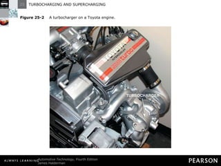
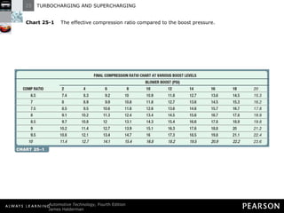
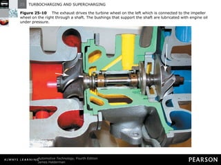
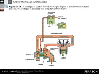
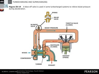
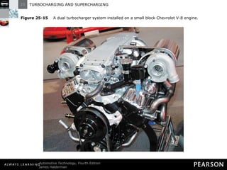
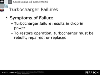
TURBOCHARGING AND SUPERCHARGING 25
Objectives The student should be able to: Prepare for ASE Engine Performance (A8) certification test content area “C” (Fuel, Air Induction, and Exhaust Systems Diagnosis and Repair).  Explain the difference between a turbocharger and a supercharger.
Objectives The student should be able to: Describe how the boost levels are controlled.  Discuss maintenance procedures for turbochargers and superchargers.
INTRODUCTION
Introduction Airflow Requirements Naturally aspirated engines use atmospheric pressure to push air-fuel mixture into combustion chamber Mixture is compressed to increase force of burning, expanding gases
Introduction Airflow Requirements The greater the compression, the greater the engine power Four-stroke engines can only take in so much air
Introduction Airflow Requirements Engine airflow requirements determined by Engine displacement Engine revolutions per minute (RPM) Volumetric efficiency
Introduction Volumetric Efficiency Measurement compares actual volume of air-gas mixture with theoretical maximum volume
Introduction Volumetric Efficiency Volumetric efficiency decreases as engine speed increases Average engine never reaches 100% volumetric efficiency New engine is about 85% efficient
Introduction Volumetric Efficiency Race engine is about 95% efficient Turbochargers or supercharges allow engines to exceed 100%
Figure 25-1   A supercharger on a Ford V-8.
Figure 25-2   A turbocharger on a Toyota engine.
FORCED INDUCTION PRINCIPLES
Forced Induction Principles Purpose and Function Force an air-fuel charge produces when ignited is a function of charge density Charge density is amount of air-fuel charge introduced into cylinders
Figure 25-3   The more air and fuel that can be packed in a cylinder, the greater the density of the air-fuel charge.
Forced Induction Principles Purpose and Function The greater the density of an air-fuel charge the greater the force produced
Forced Induction Principles Purpose and Function Engine using atmospheric pressure for intake charge is naturally aspirated
Forced Induction Principles Purpose and Function A better way to increase air density is with air pump such as turbocharger or supercharger
Forced Induction Principles Purpose and Function Pumping air into cylinder provides combustion chamber with increased air pressure known as boost
Forced Induction Principles Purpose and Function Boost can be measured several ways Pounds per square inch (PSI)
Forced Induction Principles Purpose and Function Boost can be measured several ways Atmospheres (ATM) (1 atmosphere is 14.7 PSI)
Forced Induction Principles Purpose and Function Boost can be measured several ways Bars (1 bar is 14.7 PSI)
Forced Induction Principles Purpose and Function Boost increases air density thereby increasing friction that heats air Increased temperature decreases air density
Forced Induction Principles Purpose and Function Increased pressure doesn’t always produce greater air density
Forced Induction Principles Forced Induction Principles Forced induction systems use air pump to pack denser air-fuel charge into cylinders The weight of the air-fuel charge is higher
Forced Induction Principles Forced Induction Principles Forced induction systems use air pump to pack denser air-fuel charge into cylinders Power is increased because it is related to weight of air-fuel charge consumed within given time period
Forced Induction Principles Forced Induction Principles Pumping air into intake system under pressure allows more air to enter intake port before valve closes
Forced Induction Principles Forced Induction Principles Increased airflow allows more fuel to be added with same air-fuel ratio Denser air-fuel charge allows greater potential energy from combustion
Forced Induction Principles Forced Induction Principles Advantages of Supercharging Increases air-fuel charge density for high-compression pressure when power is needed
Forced Induction Principles Forced Induction Principles Advantages of Supercharging Engine runs on lower pressures when additional power is not needed
Forced Induction Principles Forced Induction Principles Advantages of Supercharging Pumped air pushes remaining exhaust from combustion chamber
Forced Induction Principles Forced Induction Principles Advantages of Supercharging Forced airflow and removal of exhaust gases lower temperature of cylinder head pistons and extends life of engine
Forced Induction Principles Forced Induction Principles Supercharger or turbocharger pressurization can be measured like atmospheric pressure
Forced Induction Principles Forced Induction Principles Atmospheric pressure drops with increased altitude Boost pressure remains the same regardless of altitude
Figure 25-4   Atmospheric pressure decreases with increases in altitude.
Forced Induction Principles Boost and Compression Ratios Boost increases amount of air drawn into cylinder during intake stroke The higher the boost pressure, the greater the compression ratio
Forced Induction Principles Boost and Compression Ratios Higher compression ratio requires superchargers and turbochargers to use the following: Forged pistons
Forced Induction Principles Boost and Compression Ratios Higher compression ratio requires superchargers and turbochargers to use the following: Stronger than normal connecting rods
Forced Induction Principles Boost and Compression Ratios Higher compression ratio requires superchargers and turbochargers to use the following: Piston oil squirters to control temperatures
Forced Induction Principles Boost and Compression Ratios Higher compression ratio requires superchargers and turbochargers to use the following: Lower compression ratio compared to naturally aspirated engines
Chart 25-1  The effective compression ratio compared to the boost pressure.
SUPERCHARGERS
Superchargers Introduction Supercharger is engine-driven air pump Boosts engine torque and power
Superchargers Introduction Provides instantaneous power increase Requires horsepower to operate
Superchargers Introduction Is not as efficient as a turbocharger Supercharger pumps air in direct relation to engine speed
Superchargers Types of Superchargers Roots Type Named for Philander and Francis Roots who patented supercharger in 1860
Superchargers Types of Superchargers Roots Type Patented as water pump for mines
Superchargers Types of Superchargers Roots Type Changed to pump air
Superchargers Types of Superchargers Roots Type Used on two-stroke-cycle Detroit diesel engines and other supercharged engines
Superchargers Types of Superchargers Roots Type Called positive displacement design: all air that enters Roots supercharger is forced through the unit
Figure 25-5   A roots-type supercharger uses two lobes to force the air around the outside of the housing and into the intake manifold.
Superchargers Types of Superchargers Centrifugal Supercharger Similar to turbocharger but mechanically driven by engine instead of being powered by hot exhaust gases
Superchargers Types of Superchargers Centrifugal Supercharger Not a positive displacement pump
Superchargers Types of Superchargers Centrifugal Supercharger Air enters centrifugal supercharger housing in the center and exits at the edges at a higher rate of speed
Superchargers Types of Superchargers Centrifugal Supercharger Speed of blades is higher than engine speed
Superchargers Supercharger Boost Control Many factory installed superchargers have a bypass valve that allows air to bypass the supercharger
Figure 25-6   The bypass actuator opens the bypass valve to control boost pressure.
Superchargers  Supercharger Boost Control Airflow is directed around supercharger under these conditions Boost pressure indicates intake manifold pressure is reaching boost levels
Superchargers  Supercharger Boost Control Airflow is directed around supercharger under these conditions Excessive pressure builds up during deceleration
Superchargers  Supercharger Boost Control Airflow is directed around supercharger under these conditions Reverse gear is selected
Superchargers Supercharger Service Usually lubricated with synthetic engine oil Oil level should be checked and oil changed as specified by manufacturer
Superchargers Supercharger Service Drive belt should be inspected and replaced as necessary Air filter should be replaced regularly
Superchargers Supercharger Service Service information should be used to service separate cooling system on many superchargers
Figure 25-7   A Ford supercharger cutaway display showing the roots-type blower and air charge cooler (intercooler). The air charge cooler is used to reduce the temperature of the compressed air before it enters the engine to increase the air charge density.
TURBOCHARGERS
Turbochargers Introduction Major disadvantage of supercharger: it takes engine power to drive it Mechanical supercharger can take up to 20% of engine power
Turbochargers Introduction Turbocharger uses heat from exhaust to power turbine wheel About half of heat energy in fuel goes out exhaust system
Turbochargers Introduction Another 25% is lost through radiator cooling Only 25% is converted to mechanical power
Turbochargers Introduction A mechanically driven pump uses some of the mechanical power Turbocharger gets energy from exhaust gases
Figure 25-8   A turbocharger uses some of the heat energy that would normally be wasted.
Turbochargers Operation Turbocharger turbine looks like centrifugal pump for supercharging Hot exhaust gases flow from combustion chamber to turbine wheel
Turbochargers Operation Gases expand as they leave engine The expansion of hot gases turn turbine wheel’s blades
Turbochargers Operation Turbocharger has two chambers connected by center housing The two chambers contain turbine wheel and impeller (compressor) wheel connected by a shaft
Figure 25-9   A turbine wheel is turned by the expanding exhaust gases.
Turbochargers Operation Turbocharger must be positioned as close as possible to exhaust manifold Hot air passes into turbocharger with minimal heat loss
Turbochargers Operation The exhaust gas rotates the turbine blades Turbine wheel and compressor wheel on same shaft and turn at same speed
Turbochargers Operation Compressor wheel draws air in through central inlet Centrifugal force pumps it through outlet at edge of housing
Turbochargers Operation Pair of bearings in center housing supports turbine and compressor wheel shaft and is lubricated by engine oil
Figure 25-10   The exhaust drives the turbine wheel on the left which is connected to the impeller wheel on the right through a shaft. The bushings that support the shaft are lubricated with engine oil under pressure.
Turbochargers Operation Turbine and compressor wheels operate with extremely close clearances to minimize leakage
Turbochargers Operation Leakage around turbine blades causes dissipation of heat energy Leakage around compressor blades reduces full boost pressure
Turbochargers Turbocharger Operation When engine is started, exhaust heat and pressure are low Turbocharger runs at low speed (about 1000 RPM)
Turbochargers Turbocharger Operation Engine works like naturally aspirated engine As engine speed and load increase, exhaust heat and flow increase
Turbochargers Turbocharger Operation Turbine and compressor wheels accelerate as heat energy increases At full engine power, turbocharger rotates between 100,000 and 150,000 RPM
Figure 25-11   Engine oil is fed to the center of the turbocharger to lubricate the bushings and returns to the oil pan through a return line.
Turbochargers Turbocharger Operation Engine deceleration from full power to idle takes a second or two because of friction, pumping resistance, and drivetrain load
Turbochargers Turbocharger Operation Turbocharger has no load Turbocharger takes a minute or more to slow to idle
Turbochargers Turbocharger Operation If engine is turned off, lubrication flow to turbocharger stops Oil in center housing reaches extreme heat and can coke or oxidize
Turbochargers Turbocharger Operation Coked oil can clog passages and reduce turbocharger life High rotating speed and close clearance of turbine and compressor require critical bearing clearances
Turbochargers Turbocharger Operation Bearings must keep radial clearances of 0.003 to 0.006 in. (0.08 to 0.15mm) Axial clearance must be maintained at 0.001 to 0.003 in. (0.025 to 0.08 mm)
Turbochargers Turbocharger Operation To avoid problems with turbocharger  Turbochargers need constant lubrication with clean oil; frequent oil changes are called for
Turbochargers Turbocharger Operation To avoid problems with turbocharger  Dirt and other contaminants must be kept out of intake and exhaust housing
Turbochargers Turbocharger Operation To avoid problems with turbocharger  When basic engine bearing has been damaged, turbocharger must be flushed with engine oil
Turbochargers Turbocharger Operation To avoid problems with turbocharger  If turbocharger is damaged, engine oil must be drained and flushed and oil filter replaced
Turbochargers Turbocharger Operation Late-model turbochargers have liquid-cooled center bearings Engine coolant is circulated through center housing
Turbochargers Turbocharger Size and Response Time Time lag exists between increase in engine speed and increase in turbocharger speed The delay is called turbo lag
Turbochargers Turbocharger Size and Response Time Unlike supercharger, turbocharger cannot supply adequate boost at low speed Response time related to size of turbine and compressor wheels
Turbochargers Turbocharger Size and Response Time Small wheels accelerate rapidly; large wheels slowly Small wheels may not have enough airflow capacity for engine
Turbochargers Turbocharger Size and Response Time Intake and exhaust breathing of engine must be matched to capabilities of turbocharger
BOOST CONTROL
Boost Control Purpose and Function Supercharged and turbocharged systems provide pressure greater than atmospheric pressure Increased pressure forces additional air into combustion chamber
Boost Control Purpose and Function Increased charge increases engine power Amount of boost is measured in pound per square inch (PSI), in inches of mercury (in. Hg), in bars, or in atmospheres
Boost Control Purpose and Function 1 atmosphere = 14.7 PSI 1 atmosphere = 29.50 in. Hg
Boost Control Purpose and Function 1 atmosphere = 1 bar 1 bar =14.7 PSI
Boost Control Boost Control Factors Factors to consider when increasing boost pressure As boost pressure increases, air temperature increases As air temperature increases, combustion temperature increases
Boost Control Boost Control Factors Factors to consider when increasing boost pressure Power can be increased by cooling compressed air after leaving turbocharger
Boost Control Boost Control Factors Factors to consider when increasing boost pressure Typical cooling device is intercooler
Boost Control Boost Control Factors Factors to consider when increasing boost pressure Intercooler is similar to radiator: outside air passes through cooling pressurized heated air
Boost Control Boost Control Factors Factors to consider when increasing boost pressure Intercooler located between turbocharger and intake manifold
Boost Control Boost Control Factors Factors to consider when increasing boost pressure Some intercoolers use engine coolant
Figure 25-12   The unit on top of this Subaru that looks like a radiator is the intercooler, which cools the air after it has been compressed by the turbocharger.
Boost Control Boost Control Factors Factors to consider when increasing boost pressure Increased combustion temperature and pressure must be limited to avoid engine damage
Boost Control Boost Control Factors Factors to consider when increasing boost pressure Maximum exhaust gas temperature is  1,440°F (840°C)
Boost Control Boost Control Factors Factors to consider when increasing boost pressure Higher temperatures can damage turbocharger and engine
Boost Control Wastegate Turbochargers use exhaust gas to increase boost The increased boost increases exhaust gas which again increases boost
Boost Control Wastegate To prevent overboost and engine damage most turbocharger systems have a wastegate A wastegate is a bypass valve at exhaust inlet to turbine
Boost Control Wastegate A wastegate can route part of exhaust past the turbine to exhaust system With less exhaust, turbocharger slows
Boost Control Wastegate Wastegate is continuous process to control boost pressure Wastegate is a pressure control valve usually controlled by computer
Figure 25-13   A wastegate is used on many turbocharged engines to control maximum boost pressure. The wastegate is controlled by a computer-controlled valve.
Boost Control Relief Valves A relief valve controls intake side of turbocharger Relief valve vents pressurized air from connecting pipe between turbocharger outlet and throttle
Boost Control Relief Valves Relief valve functions when throttle is closed during boost If pressure is not released, turbocharger will lag when throttle is opened again
Boost Control Relief Valves Two basic types of relief valves Compressor by pass valve (CBV) is quieter and routes pressurized air to inlet for reuse
Boost Control Relief Valves Blow-off valve (BOV) --also called dump valve or vent valve--uses adjustable spring to close valve until release of throttle
Figure 25-14   A blow-off valve is used in some turbocharged systems to relieve boost pressure during deceleration.
Figure 25-15   A dual turbocharger system installed on a small block Chevrolet V-8 engine.
TURBOCHARGER FAILURES
Turbocharger Failures Symptoms of Failure Turbocharger failure results in drop in power To restore operation, turbocharger must be rebuilt, repaired, or replaced
Turbocharger Failures Symptoms of Failure Turbochargers cannot be removed from vehicle Bearing failure common cause of turbocharger failure
Turbocharger Failures Symptoms of Failure Another problem is excessive and continuous oil consumption Turbochargers use small rings to prevent exhaust from entering central bearing
Turbocharger Failures Symptoms of Failure Excessive oil consumption is usually caused by one of the following Plugged positive crankcase ventilation (PCV) system
Turbocharger Failures Symptoms of Failure Excessive oil consumption is usually caused by one of the following Clogged air filter, causing low-pressure area in inlet and drawing oil past turbo shaft rings
Turbocharger Failures Symptoms of Failure Excessive oil consumption is usually caused by one of the following Clogged oil return (drain) line from turbocharger to oil pan
Turbocharger Failures Preventing Turbocharger Failures Regular oil changes (synthetic oil is best) Regular air filter replacement intervals Recommended inspections and services
NITROUS OXIDE
Nitrous Oxide Introduction Nitrous oxide is for racing or high performance only Relatively inexpensive way to get additional power
Nitrous Oxide Introduction Serious engine damage can occur if used incorrectly or excessively
Nitrous Oxide Principles Nitrous oxide (N 2 O) is colorless, nonflammable gas Discovered by British chemist Joseph Priestly
Nitrous Oxide Principles Causes light-headedness if breathed (known as laughing gas) Once used in dentistry to reduce pain  Nitrous oxide is a manufactured gas
Nitrous Oxide Engine Power Adder Power adder is device or system added to engine, such as supercharger, turbocharger, or nitrous oxide to increase power
Nitrous Oxide Engine Power Adder Nitrous oxide injected into engine along with extra gasoline N 2 O adds extra oxygen for extra fuel
Nitrous Oxide Engine Power Adder NOTE: Nitrous oxide was used as power adder in World War II on some fighter aircraft. Having several hundred more horsepower for a short time saved many lives.
Nitrous Oxide Pressure and Temperature Requires about 11 lb of pressure per degree Fahrenheit to condense nitrous oxide gas into liquid nitrous oxide
Nitrous Oxide Pressure and Temperature To change N 2 O from liquid to gas, all that is needed is to lower its pressure below the pressure it takes to cause it to become a liquid.
Chart 25-2  Temperature/pressure relation for nitrous oxide: The higher the temperature, the higher the pressure.
Nitrous Oxide Pressure and Temperature Temperature affects pressure of N 2 O N 2 O is stored in pressurized container
Nitrous Oxide Pressure and Temperature Installed at angle so pickup tube is in the liquid Front or discharge end of bottle should be toward front of vehicle
Figure 25-16   Nitrous bottles have to be mounted at an angle to ensure that the pickup tube is in the liquid N 2 O.
Nitrous Oxide Wet and Dry System Two types of N 2 O systems Wet system involves additional fuel being injected
Nitrous Oxide Wet and Dry System Two types of N 2 O systems Identified by two nozzles; red supplying gasoline and blue supplying N 2 O
Nitrous Oxide Wet and Dry System Two types of N 2 O systems Dry system does not include gasoline
Nitrous Oxide Wet and Dry System Two types of N 2 O systems PCM can be commanded to provide more fuel when N 2 O is sprayed
Nitrous Oxide Engine Changes Needed for N 2 O If N 2 O is used to increase horsepower more than 50 hp, engine must be designed and built for greater heat and pressure
Nitrous Oxide Engine Changes Needed for N 2 O The following items should be considered for adding turbocharger, supercharger, or nitrous oxide Forged pistons to withstand increased pressure and temperature
Nitrous Oxide Engine Changes Needed for N 2 O The following items should be considered for adding turbocharger, supercharger, or nitrous oxide Cylinder-to-wall clearance increase to compensate for greater heat
Nitrous Oxide Engine Changes Needed for N 2 O The following items should be considered for adding turbocharger, supercharger, or nitrous oxide Forged crankshaft and connecting rods
Nitrous Oxide Engine Changes Needed for N 2 O Check instructions from N 2 O supplier for details and other changes
Nitrous Oxide Engine Changes Needed for N 2 O CAUTION: The use of nitrous oxide injection system can cause catastrophic engine damage. Always follow instructions that come with the kit and be sure all internal engine parts meet standard specified to help avoid severe engine damage.
Nitrous Oxide System Installation and Calibration Nitrous oxide systems usually purchased as kit Kit includes one or more sizes of nozzles calibrated to control flow of N 2 O
Nitrous Oxide System Installation and Calibration Sizes of nozzles are calibrated in horsepower gained by their use 50 hp 100 hp 150 hp
Nitrous Oxide System Installation and Calibration Installation of N 2 O kit includes on-off switch and switch on or near throttle Switch is activated only when throttle is fully opened (WOT)
TECH TIP Faster Moves More Air One of the high-performance measures that can be used to increase horsepower on a supercharged engine is to install a smaller diameter pulley. The smaller the pulley diameter, the faster the supercharger will rotate and the higher the potential boost pressure will be.  BACK TO  PRESENTATION The change will require a shorter belt, and the extra boost could cause serious engine damage.
TECH TIP Boost Is the Result of Restriction The boost pressure of a turbocharger (or supercharger) is commonly measured in pounds per square inch. If a cylinder head is restricted because of small valves and ports, the turbocharger will quickly provide boost. BACK TO  PRESENTATION Boost results when the air being forced into the cylinder heads cannot flow into the cylinders fast enough and “piles up” in the intake manifold, increasing boost pressure. If an engine had large valves and ports, the turbocharger could provide a much greater amount of air into the engine at the same boost pressure as an identical engine with smaller valves and ports. Therefore, by increasing the size of the valves, a turbocharged or supercharged engine will be capable of producing much greater power.
TECH TIP If One Is Good, Two Are Better A turbocharger uses the exhaust from the engine to spin a turbine, which is connected to an impeller inside a turbocharger. This impeller then forces air into the engine under pressure, higher than is normally achieved without a turbocharger. The more air that can be forced into an engine, the greater the power potential. BACK TO  PRESENTATION A V-type engine has two exhaust manifolds and so two small turbochargers can be used to help force greater quantities of air into an engine, as shown in FIGURE 25–15. Figure 25-15   A dual turbocharger system installed on a small block Chevrolet V-8 engine.
TECH TIP Increase Bottle Pressure To increase the pressure of the nitrous oxide in a bottle, an electrical warming blanket can be used, as seen in FIGURE 25–17. The higher the temperature, the higher the pressure and the greater the amount of N 2 O flow when energized. BACK TO  PRESENTATION Figure 25-17   An electrical heating mat is installed on the bottle of nitrous oxide to increase the pressure of the gas inside.

Halderman ch025 lecture

  • 1.
  • 2.
    Objectives The studentshould be able to: Prepare for ASE Engine Performance (A8) certification test content area “C” (Fuel, Air Induction, and Exhaust Systems Diagnosis and Repair). Explain the difference between a turbocharger and a supercharger.
  • 3.
    Objectives The studentshould be able to: Describe how the boost levels are controlled. Discuss maintenance procedures for turbochargers and superchargers.
  • 4.
  • 5.
    Introduction Airflow RequirementsNaturally aspirated engines use atmospheric pressure to push air-fuel mixture into combustion chamber Mixture is compressed to increase force of burning, expanding gases
  • 6.
    Introduction Airflow RequirementsThe greater the compression, the greater the engine power Four-stroke engines can only take in so much air
  • 7.
    Introduction Airflow RequirementsEngine airflow requirements determined by Engine displacement Engine revolutions per minute (RPM) Volumetric efficiency
  • 8.
    Introduction Volumetric EfficiencyMeasurement compares actual volume of air-gas mixture with theoretical maximum volume
  • 9.
    Introduction Volumetric EfficiencyVolumetric efficiency decreases as engine speed increases Average engine never reaches 100% volumetric efficiency New engine is about 85% efficient
  • 10.
    Introduction Volumetric EfficiencyRace engine is about 95% efficient Turbochargers or supercharges allow engines to exceed 100%
  • 11.
    Figure 25-1 A supercharger on a Ford V-8.
  • 12.
    Figure 25-2 A turbocharger on a Toyota engine.
  • 13.
  • 14.
    Forced Induction PrinciplesPurpose and Function Force an air-fuel charge produces when ignited is a function of charge density Charge density is amount of air-fuel charge introduced into cylinders
  • 15.
    Figure 25-3 The more air and fuel that can be packed in a cylinder, the greater the density of the air-fuel charge.
  • 16.
    Forced Induction PrinciplesPurpose and Function The greater the density of an air-fuel charge the greater the force produced
  • 17.
    Forced Induction PrinciplesPurpose and Function Engine using atmospheric pressure for intake charge is naturally aspirated
  • 18.
    Forced Induction PrinciplesPurpose and Function A better way to increase air density is with air pump such as turbocharger or supercharger
  • 19.
    Forced Induction PrinciplesPurpose and Function Pumping air into cylinder provides combustion chamber with increased air pressure known as boost
  • 20.
    Forced Induction PrinciplesPurpose and Function Boost can be measured several ways Pounds per square inch (PSI)
  • 21.
    Forced Induction PrinciplesPurpose and Function Boost can be measured several ways Atmospheres (ATM) (1 atmosphere is 14.7 PSI)
  • 22.
    Forced Induction PrinciplesPurpose and Function Boost can be measured several ways Bars (1 bar is 14.7 PSI)
  • 23.
    Forced Induction PrinciplesPurpose and Function Boost increases air density thereby increasing friction that heats air Increased temperature decreases air density
  • 24.
    Forced Induction PrinciplesPurpose and Function Increased pressure doesn’t always produce greater air density
  • 25.
    Forced Induction PrinciplesForced Induction Principles Forced induction systems use air pump to pack denser air-fuel charge into cylinders The weight of the air-fuel charge is higher
  • 26.
    Forced Induction PrinciplesForced Induction Principles Forced induction systems use air pump to pack denser air-fuel charge into cylinders Power is increased because it is related to weight of air-fuel charge consumed within given time period
  • 27.
    Forced Induction PrinciplesForced Induction Principles Pumping air into intake system under pressure allows more air to enter intake port before valve closes
  • 28.
    Forced Induction PrinciplesForced Induction Principles Increased airflow allows more fuel to be added with same air-fuel ratio Denser air-fuel charge allows greater potential energy from combustion
  • 29.
    Forced Induction PrinciplesForced Induction Principles Advantages of Supercharging Increases air-fuel charge density for high-compression pressure when power is needed
  • 30.
    Forced Induction PrinciplesForced Induction Principles Advantages of Supercharging Engine runs on lower pressures when additional power is not needed
  • 31.
    Forced Induction PrinciplesForced Induction Principles Advantages of Supercharging Pumped air pushes remaining exhaust from combustion chamber
  • 32.
    Forced Induction PrinciplesForced Induction Principles Advantages of Supercharging Forced airflow and removal of exhaust gases lower temperature of cylinder head pistons and extends life of engine
  • 33.
    Forced Induction PrinciplesForced Induction Principles Supercharger or turbocharger pressurization can be measured like atmospheric pressure
  • 34.
    Forced Induction PrinciplesForced Induction Principles Atmospheric pressure drops with increased altitude Boost pressure remains the same regardless of altitude
  • 35.
    Figure 25-4 Atmospheric pressure decreases with increases in altitude.
  • 36.
    Forced Induction PrinciplesBoost and Compression Ratios Boost increases amount of air drawn into cylinder during intake stroke The higher the boost pressure, the greater the compression ratio
  • 37.
    Forced Induction PrinciplesBoost and Compression Ratios Higher compression ratio requires superchargers and turbochargers to use the following: Forged pistons
  • 38.
    Forced Induction PrinciplesBoost and Compression Ratios Higher compression ratio requires superchargers and turbochargers to use the following: Stronger than normal connecting rods
  • 39.
    Forced Induction PrinciplesBoost and Compression Ratios Higher compression ratio requires superchargers and turbochargers to use the following: Piston oil squirters to control temperatures
  • 40.
    Forced Induction PrinciplesBoost and Compression Ratios Higher compression ratio requires superchargers and turbochargers to use the following: Lower compression ratio compared to naturally aspirated engines
  • 41.
    Chart 25-1 The effective compression ratio compared to the boost pressure.
  • 42.
  • 43.
    Superchargers Introduction Superchargeris engine-driven air pump Boosts engine torque and power
  • 44.
    Superchargers Introduction Providesinstantaneous power increase Requires horsepower to operate
  • 45.
    Superchargers Introduction Isnot as efficient as a turbocharger Supercharger pumps air in direct relation to engine speed
  • 46.
    Superchargers Types ofSuperchargers Roots Type Named for Philander and Francis Roots who patented supercharger in 1860
  • 47.
    Superchargers Types ofSuperchargers Roots Type Patented as water pump for mines
  • 48.
    Superchargers Types ofSuperchargers Roots Type Changed to pump air
  • 49.
    Superchargers Types ofSuperchargers Roots Type Used on two-stroke-cycle Detroit diesel engines and other supercharged engines
  • 50.
    Superchargers Types ofSuperchargers Roots Type Called positive displacement design: all air that enters Roots supercharger is forced through the unit
  • 51.
    Figure 25-5 A roots-type supercharger uses two lobes to force the air around the outside of the housing and into the intake manifold.
  • 52.
    Superchargers Types ofSuperchargers Centrifugal Supercharger Similar to turbocharger but mechanically driven by engine instead of being powered by hot exhaust gases
  • 53.
    Superchargers Types ofSuperchargers Centrifugal Supercharger Not a positive displacement pump
  • 54.
    Superchargers Types ofSuperchargers Centrifugal Supercharger Air enters centrifugal supercharger housing in the center and exits at the edges at a higher rate of speed
  • 55.
    Superchargers Types ofSuperchargers Centrifugal Supercharger Speed of blades is higher than engine speed
  • 56.
    Superchargers Supercharger BoostControl Many factory installed superchargers have a bypass valve that allows air to bypass the supercharger
  • 57.
    Figure 25-6 The bypass actuator opens the bypass valve to control boost pressure.
  • 58.
    Superchargers SuperchargerBoost Control Airflow is directed around supercharger under these conditions Boost pressure indicates intake manifold pressure is reaching boost levels
  • 59.
    Superchargers SuperchargerBoost Control Airflow is directed around supercharger under these conditions Excessive pressure builds up during deceleration
  • 60.
    Superchargers SuperchargerBoost Control Airflow is directed around supercharger under these conditions Reverse gear is selected
  • 61.
    Superchargers Supercharger ServiceUsually lubricated with synthetic engine oil Oil level should be checked and oil changed as specified by manufacturer
  • 62.
    Superchargers Supercharger ServiceDrive belt should be inspected and replaced as necessary Air filter should be replaced regularly
  • 63.
    Superchargers Supercharger ServiceService information should be used to service separate cooling system on many superchargers
  • 64.
    Figure 25-7 A Ford supercharger cutaway display showing the roots-type blower and air charge cooler (intercooler). The air charge cooler is used to reduce the temperature of the compressed air before it enters the engine to increase the air charge density.
  • 65.
  • 66.
    Turbochargers Introduction Majordisadvantage of supercharger: it takes engine power to drive it Mechanical supercharger can take up to 20% of engine power
  • 67.
    Turbochargers Introduction Turbochargeruses heat from exhaust to power turbine wheel About half of heat energy in fuel goes out exhaust system
  • 68.
    Turbochargers Introduction Another25% is lost through radiator cooling Only 25% is converted to mechanical power
  • 69.
    Turbochargers Introduction Amechanically driven pump uses some of the mechanical power Turbocharger gets energy from exhaust gases
  • 70.
    Figure 25-8 A turbocharger uses some of the heat energy that would normally be wasted.
  • 71.
    Turbochargers Operation Turbochargerturbine looks like centrifugal pump for supercharging Hot exhaust gases flow from combustion chamber to turbine wheel
  • 72.
    Turbochargers Operation Gasesexpand as they leave engine The expansion of hot gases turn turbine wheel’s blades
  • 73.
    Turbochargers Operation Turbochargerhas two chambers connected by center housing The two chambers contain turbine wheel and impeller (compressor) wheel connected by a shaft
  • 74.
    Figure 25-9 A turbine wheel is turned by the expanding exhaust gases.
  • 75.
    Turbochargers Operation Turbochargermust be positioned as close as possible to exhaust manifold Hot air passes into turbocharger with minimal heat loss
  • 76.
    Turbochargers Operation Theexhaust gas rotates the turbine blades Turbine wheel and compressor wheel on same shaft and turn at same speed
  • 77.
    Turbochargers Operation Compressorwheel draws air in through central inlet Centrifugal force pumps it through outlet at edge of housing
  • 78.
    Turbochargers Operation Pairof bearings in center housing supports turbine and compressor wheel shaft and is lubricated by engine oil
  • 79.
    Figure 25-10 The exhaust drives the turbine wheel on the left which is connected to the impeller wheel on the right through a shaft. The bushings that support the shaft are lubricated with engine oil under pressure.
  • 80.
    Turbochargers Operation Turbineand compressor wheels operate with extremely close clearances to minimize leakage
  • 81.
    Turbochargers Operation Leakagearound turbine blades causes dissipation of heat energy Leakage around compressor blades reduces full boost pressure
  • 82.
    Turbochargers Turbocharger OperationWhen engine is started, exhaust heat and pressure are low Turbocharger runs at low speed (about 1000 RPM)
  • 83.
    Turbochargers Turbocharger OperationEngine works like naturally aspirated engine As engine speed and load increase, exhaust heat and flow increase
  • 84.
    Turbochargers Turbocharger OperationTurbine and compressor wheels accelerate as heat energy increases At full engine power, turbocharger rotates between 100,000 and 150,000 RPM
  • 85.
    Figure 25-11 Engine oil is fed to the center of the turbocharger to lubricate the bushings and returns to the oil pan through a return line.
  • 86.
    Turbochargers Turbocharger OperationEngine deceleration from full power to idle takes a second or two because of friction, pumping resistance, and drivetrain load
  • 87.
    Turbochargers Turbocharger OperationTurbocharger has no load Turbocharger takes a minute or more to slow to idle
  • 88.
    Turbochargers Turbocharger OperationIf engine is turned off, lubrication flow to turbocharger stops Oil in center housing reaches extreme heat and can coke or oxidize
  • 89.
    Turbochargers Turbocharger OperationCoked oil can clog passages and reduce turbocharger life High rotating speed and close clearance of turbine and compressor require critical bearing clearances
  • 90.
    Turbochargers Turbocharger OperationBearings must keep radial clearances of 0.003 to 0.006 in. (0.08 to 0.15mm) Axial clearance must be maintained at 0.001 to 0.003 in. (0.025 to 0.08 mm)
  • 91.
    Turbochargers Turbocharger OperationTo avoid problems with turbocharger Turbochargers need constant lubrication with clean oil; frequent oil changes are called for
  • 92.
    Turbochargers Turbocharger OperationTo avoid problems with turbocharger Dirt and other contaminants must be kept out of intake and exhaust housing
  • 93.
    Turbochargers Turbocharger OperationTo avoid problems with turbocharger When basic engine bearing has been damaged, turbocharger must be flushed with engine oil
  • 94.
    Turbochargers Turbocharger OperationTo avoid problems with turbocharger If turbocharger is damaged, engine oil must be drained and flushed and oil filter replaced
  • 95.
    Turbochargers Turbocharger OperationLate-model turbochargers have liquid-cooled center bearings Engine coolant is circulated through center housing
  • 96.
    Turbochargers Turbocharger Sizeand Response Time Time lag exists between increase in engine speed and increase in turbocharger speed The delay is called turbo lag
  • 97.
    Turbochargers Turbocharger Sizeand Response Time Unlike supercharger, turbocharger cannot supply adequate boost at low speed Response time related to size of turbine and compressor wheels
  • 98.
    Turbochargers Turbocharger Sizeand Response Time Small wheels accelerate rapidly; large wheels slowly Small wheels may not have enough airflow capacity for engine
  • 99.
    Turbochargers Turbocharger Sizeand Response Time Intake and exhaust breathing of engine must be matched to capabilities of turbocharger
  • 100.
  • 101.
    Boost Control Purposeand Function Supercharged and turbocharged systems provide pressure greater than atmospheric pressure Increased pressure forces additional air into combustion chamber
  • 102.
    Boost Control Purposeand Function Increased charge increases engine power Amount of boost is measured in pound per square inch (PSI), in inches of mercury (in. Hg), in bars, or in atmospheres
  • 103.
    Boost Control Purposeand Function 1 atmosphere = 14.7 PSI 1 atmosphere = 29.50 in. Hg
  • 104.
    Boost Control Purposeand Function 1 atmosphere = 1 bar 1 bar =14.7 PSI
  • 105.
    Boost Control BoostControl Factors Factors to consider when increasing boost pressure As boost pressure increases, air temperature increases As air temperature increases, combustion temperature increases
  • 106.
    Boost Control BoostControl Factors Factors to consider when increasing boost pressure Power can be increased by cooling compressed air after leaving turbocharger
  • 107.
    Boost Control BoostControl Factors Factors to consider when increasing boost pressure Typical cooling device is intercooler
  • 108.
    Boost Control BoostControl Factors Factors to consider when increasing boost pressure Intercooler is similar to radiator: outside air passes through cooling pressurized heated air
  • 109.
    Boost Control BoostControl Factors Factors to consider when increasing boost pressure Intercooler located between turbocharger and intake manifold
  • 110.
    Boost Control BoostControl Factors Factors to consider when increasing boost pressure Some intercoolers use engine coolant
  • 111.
    Figure 25-12 The unit on top of this Subaru that looks like a radiator is the intercooler, which cools the air after it has been compressed by the turbocharger.
  • 112.
    Boost Control BoostControl Factors Factors to consider when increasing boost pressure Increased combustion temperature and pressure must be limited to avoid engine damage
  • 113.
    Boost Control BoostControl Factors Factors to consider when increasing boost pressure Maximum exhaust gas temperature is 1,440°F (840°C)
  • 114.
    Boost Control BoostControl Factors Factors to consider when increasing boost pressure Higher temperatures can damage turbocharger and engine
  • 115.
    Boost Control WastegateTurbochargers use exhaust gas to increase boost The increased boost increases exhaust gas which again increases boost
  • 116.
    Boost Control WastegateTo prevent overboost and engine damage most turbocharger systems have a wastegate A wastegate is a bypass valve at exhaust inlet to turbine
  • 117.
    Boost Control WastegateA wastegate can route part of exhaust past the turbine to exhaust system With less exhaust, turbocharger slows
  • 118.
    Boost Control WastegateWastegate is continuous process to control boost pressure Wastegate is a pressure control valve usually controlled by computer
  • 119.
    Figure 25-13 A wastegate is used on many turbocharged engines to control maximum boost pressure. The wastegate is controlled by a computer-controlled valve.
  • 120.
    Boost Control ReliefValves A relief valve controls intake side of turbocharger Relief valve vents pressurized air from connecting pipe between turbocharger outlet and throttle
  • 121.
    Boost Control ReliefValves Relief valve functions when throttle is closed during boost If pressure is not released, turbocharger will lag when throttle is opened again
  • 122.
    Boost Control ReliefValves Two basic types of relief valves Compressor by pass valve (CBV) is quieter and routes pressurized air to inlet for reuse
  • 123.
    Boost Control ReliefValves Blow-off valve (BOV) --also called dump valve or vent valve--uses adjustable spring to close valve until release of throttle
  • 124.
    Figure 25-14 A blow-off valve is used in some turbocharged systems to relieve boost pressure during deceleration.
  • 125.
    Figure 25-15 A dual turbocharger system installed on a small block Chevrolet V-8 engine.
  • 126.
  • 127.
    Turbocharger Failures Symptomsof Failure Turbocharger failure results in drop in power To restore operation, turbocharger must be rebuilt, repaired, or replaced
  • 128.
    Turbocharger Failures Symptomsof Failure Turbochargers cannot be removed from vehicle Bearing failure common cause of turbocharger failure
  • 129.
    Turbocharger Failures Symptomsof Failure Another problem is excessive and continuous oil consumption Turbochargers use small rings to prevent exhaust from entering central bearing
  • 130.
    Turbocharger Failures Symptomsof Failure Excessive oil consumption is usually caused by one of the following Plugged positive crankcase ventilation (PCV) system
  • 131.
    Turbocharger Failures Symptomsof Failure Excessive oil consumption is usually caused by one of the following Clogged air filter, causing low-pressure area in inlet and drawing oil past turbo shaft rings
  • 132.
    Turbocharger Failures Symptomsof Failure Excessive oil consumption is usually caused by one of the following Clogged oil return (drain) line from turbocharger to oil pan
  • 133.
    Turbocharger Failures PreventingTurbocharger Failures Regular oil changes (synthetic oil is best) Regular air filter replacement intervals Recommended inspections and services
  • 134.
  • 135.
    Nitrous Oxide IntroductionNitrous oxide is for racing or high performance only Relatively inexpensive way to get additional power
  • 136.
    Nitrous Oxide IntroductionSerious engine damage can occur if used incorrectly or excessively
  • 137.
    Nitrous Oxide PrinciplesNitrous oxide (N 2 O) is colorless, nonflammable gas Discovered by British chemist Joseph Priestly
  • 138.
    Nitrous Oxide PrinciplesCauses light-headedness if breathed (known as laughing gas) Once used in dentistry to reduce pain Nitrous oxide is a manufactured gas
  • 139.
    Nitrous Oxide EnginePower Adder Power adder is device or system added to engine, such as supercharger, turbocharger, or nitrous oxide to increase power
  • 140.
    Nitrous Oxide EnginePower Adder Nitrous oxide injected into engine along with extra gasoline N 2 O adds extra oxygen for extra fuel
  • 141.
    Nitrous Oxide EnginePower Adder NOTE: Nitrous oxide was used as power adder in World War II on some fighter aircraft. Having several hundred more horsepower for a short time saved many lives.
  • 142.
    Nitrous Oxide Pressureand Temperature Requires about 11 lb of pressure per degree Fahrenheit to condense nitrous oxide gas into liquid nitrous oxide
  • 143.
    Nitrous Oxide Pressureand Temperature To change N 2 O from liquid to gas, all that is needed is to lower its pressure below the pressure it takes to cause it to become a liquid.
  • 144.
    Chart 25-2 Temperature/pressure relation for nitrous oxide: The higher the temperature, the higher the pressure.
  • 145.
    Nitrous Oxide Pressureand Temperature Temperature affects pressure of N 2 O N 2 O is stored in pressurized container
  • 146.
    Nitrous Oxide Pressureand Temperature Installed at angle so pickup tube is in the liquid Front or discharge end of bottle should be toward front of vehicle
  • 147.
    Figure 25-16 Nitrous bottles have to be mounted at an angle to ensure that the pickup tube is in the liquid N 2 O.
  • 148.
    Nitrous Oxide Wetand Dry System Two types of N 2 O systems Wet system involves additional fuel being injected
  • 149.
    Nitrous Oxide Wetand Dry System Two types of N 2 O systems Identified by two nozzles; red supplying gasoline and blue supplying N 2 O
  • 150.
    Nitrous Oxide Wetand Dry System Two types of N 2 O systems Dry system does not include gasoline
  • 151.
    Nitrous Oxide Wetand Dry System Two types of N 2 O systems PCM can be commanded to provide more fuel when N 2 O is sprayed
  • 152.
    Nitrous Oxide EngineChanges Needed for N 2 O If N 2 O is used to increase horsepower more than 50 hp, engine must be designed and built for greater heat and pressure
  • 153.
    Nitrous Oxide EngineChanges Needed for N 2 O The following items should be considered for adding turbocharger, supercharger, or nitrous oxide Forged pistons to withstand increased pressure and temperature
  • 154.
    Nitrous Oxide EngineChanges Needed for N 2 O The following items should be considered for adding turbocharger, supercharger, or nitrous oxide Cylinder-to-wall clearance increase to compensate for greater heat
  • 155.
    Nitrous Oxide EngineChanges Needed for N 2 O The following items should be considered for adding turbocharger, supercharger, or nitrous oxide Forged crankshaft and connecting rods
  • 156.
    Nitrous Oxide EngineChanges Needed for N 2 O Check instructions from N 2 O supplier for details and other changes
  • 157.
    Nitrous Oxide EngineChanges Needed for N 2 O CAUTION: The use of nitrous oxide injection system can cause catastrophic engine damage. Always follow instructions that come with the kit and be sure all internal engine parts meet standard specified to help avoid severe engine damage.
  • 158.
    Nitrous Oxide SystemInstallation and Calibration Nitrous oxide systems usually purchased as kit Kit includes one or more sizes of nozzles calibrated to control flow of N 2 O
  • 159.
    Nitrous Oxide SystemInstallation and Calibration Sizes of nozzles are calibrated in horsepower gained by their use 50 hp 100 hp 150 hp
  • 160.
    Nitrous Oxide SystemInstallation and Calibration Installation of N 2 O kit includes on-off switch and switch on or near throttle Switch is activated only when throttle is fully opened (WOT)
  • 161.
    TECH TIP FasterMoves More Air One of the high-performance measures that can be used to increase horsepower on a supercharged engine is to install a smaller diameter pulley. The smaller the pulley diameter, the faster the supercharger will rotate and the higher the potential boost pressure will be. BACK TO PRESENTATION The change will require a shorter belt, and the extra boost could cause serious engine damage.
  • 162.
    TECH TIP BoostIs the Result of Restriction The boost pressure of a turbocharger (or supercharger) is commonly measured in pounds per square inch. If a cylinder head is restricted because of small valves and ports, the turbocharger will quickly provide boost. BACK TO PRESENTATION Boost results when the air being forced into the cylinder heads cannot flow into the cylinders fast enough and “piles up” in the intake manifold, increasing boost pressure. If an engine had large valves and ports, the turbocharger could provide a much greater amount of air into the engine at the same boost pressure as an identical engine with smaller valves and ports. Therefore, by increasing the size of the valves, a turbocharged or supercharged engine will be capable of producing much greater power.
  • 163.
    TECH TIP IfOne Is Good, Two Are Better A turbocharger uses the exhaust from the engine to spin a turbine, which is connected to an impeller inside a turbocharger. This impeller then forces air into the engine under pressure, higher than is normally achieved without a turbocharger. The more air that can be forced into an engine, the greater the power potential. BACK TO PRESENTATION A V-type engine has two exhaust manifolds and so two small turbochargers can be used to help force greater quantities of air into an engine, as shown in FIGURE 25–15. Figure 25-15 A dual turbocharger system installed on a small block Chevrolet V-8 engine.
  • 164.
    TECH TIP IncreaseBottle Pressure To increase the pressure of the nitrous oxide in a bottle, an electrical warming blanket can be used, as seen in FIGURE 25–17. The higher the temperature, the higher the pressure and the greater the amount of N 2 O flow when energized. BACK TO PRESENTATION Figure 25-17 An electrical heating mat is installed on the bottle of nitrous oxide to increase the pressure of the gas inside.

Editor's Notes

  • #12 Figure 25-1 A supercharger on a Ford V-8.
  • #13 Figure 25-2 A turbocharger on a Toyota engine.
  • #16 Figure 25-3 The more air and fuel that can be packed in a cylinder, the greater the density of the air-fuel charge.
  • #36 Figure 25-4 Atmospheric pressure decreases with increases in altitude.
  • #42 Chart 25-1 The effective compression ratio compared to the boost pressure.
  • #52 Figure 25-5 A roots-type supercharger uses two lobes to force the air around the outside of the housing and into the intake manifold.
  • #58 Figure 25-6 The bypass actuator opens the bypass valve to control boost pressure.
  • #65 Figure 25-7 A Ford supercharger cutaway display showing the roots-type blower and air charge cooler (intercooler). The air charge cooler is used to reduce the temperature of the compressed air before it enters the engine to increase the air charge density.
  • #71 Figure 25-8 A turbocharger uses some of the heat energy that would normally be wasted.
  • #75 Figure 25-9 A turbine wheel is turned by the expanding exhaust gases.
  • #80 Figure 25-10 The exhaust drives the turbine wheel on the left which is connected to the impeller wheel on the right through a shaft. The bushings that support the shaft are lubricated with engine oil under pressure.
  • #86 Figure 25-11 Engine oil is fed to the center of the turbocharger to lubricate the bushings and returns to the oil pan through a return line.
  • #112 Figure 25-12 The unit on top of this Subaru that looks like a radiator is the intercooler, which cools the air after it has been compressed by the turbocharger.
  • #120 Figure 25-13 A wastegate is used on many turbocharged engines to control maximum boost pressure. The wastegate is controlled by a computer-controlled valve.
  • #125 Figure 25-14 A blow-off valve is used in some turbocharged systems to relieve boost pressure during deceleration.
  • #126 Figure 25-15 A dual turbocharger system installed on a small block Chevrolet V-8 engine.
  • #145 Chart 25-2 Temperature/pressure relation for nitrous oxide: The higher the temperature, the higher the pressure.
  • #148 Figure 25-16 Nitrous bottles have to be mounted at an angle to ensure that the pickup tube is in the liquid N 2 O.