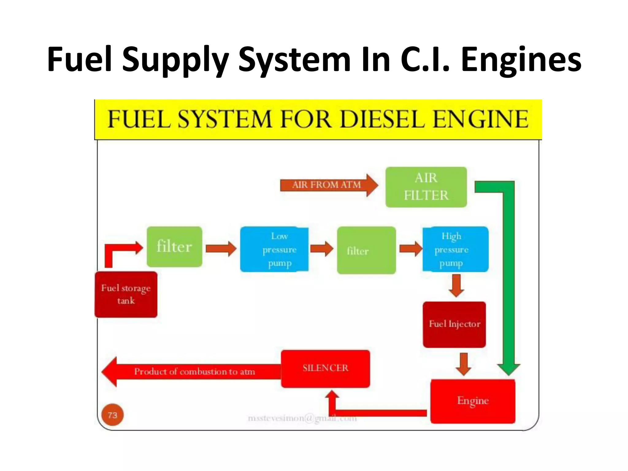
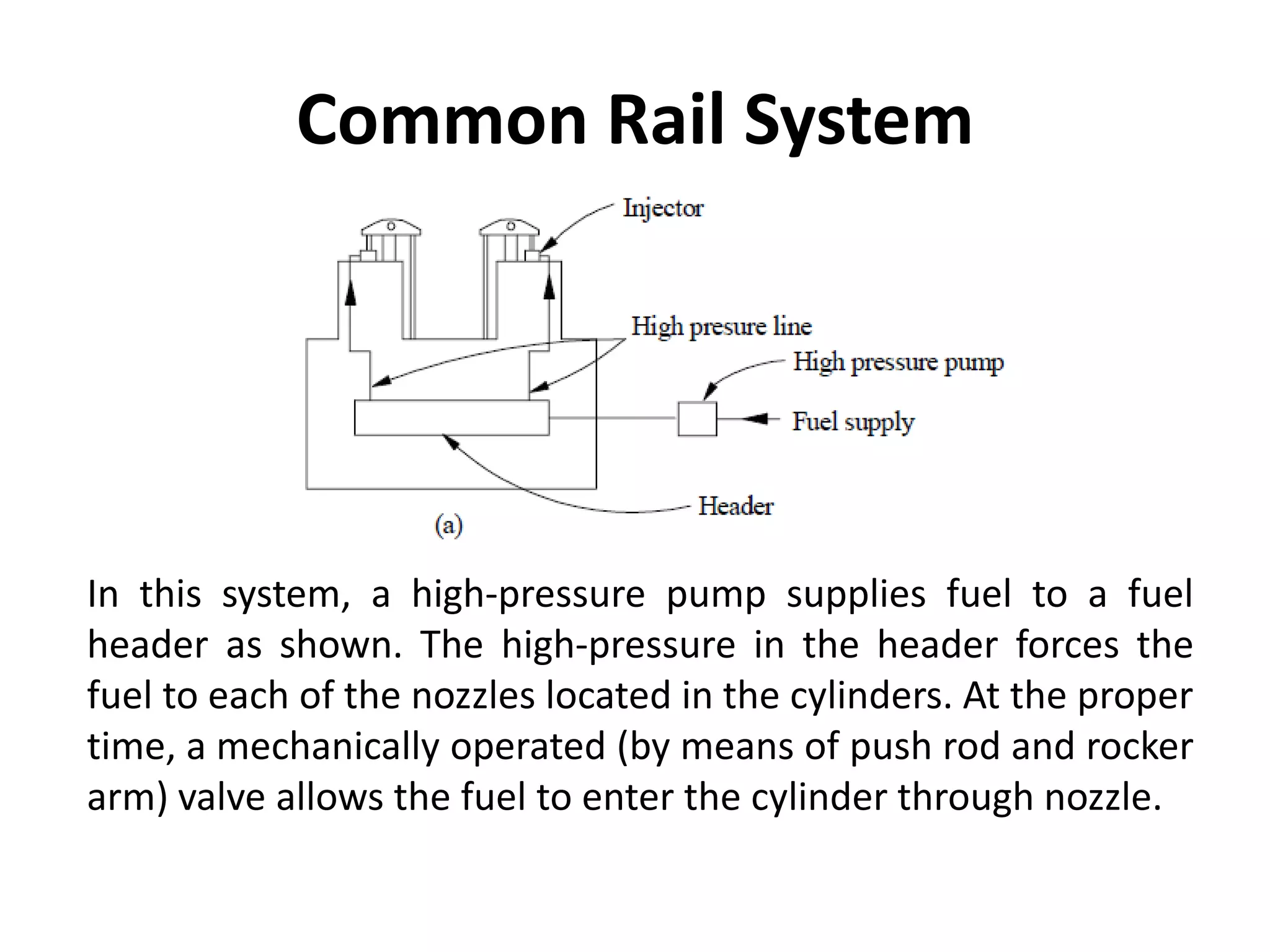
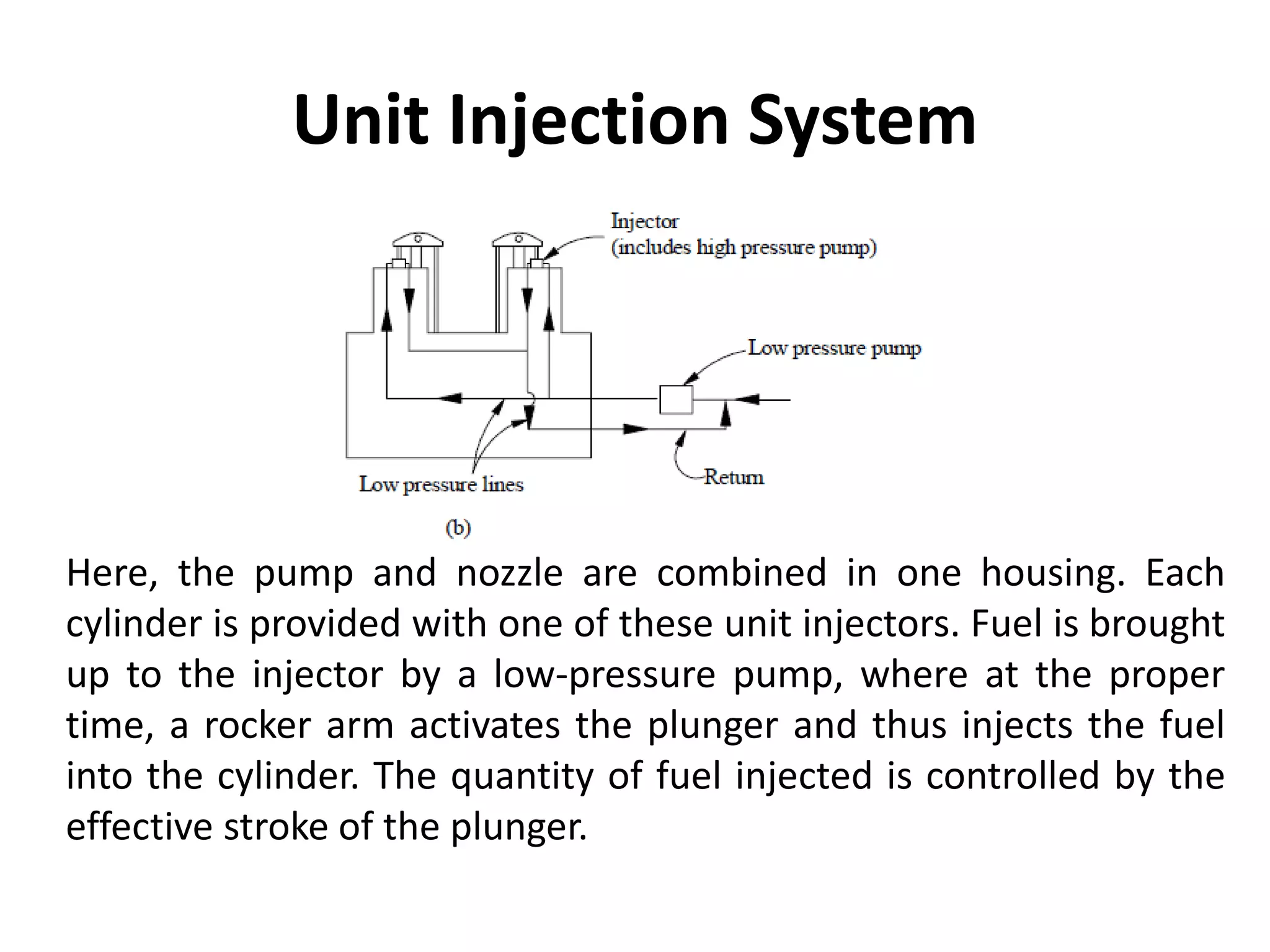
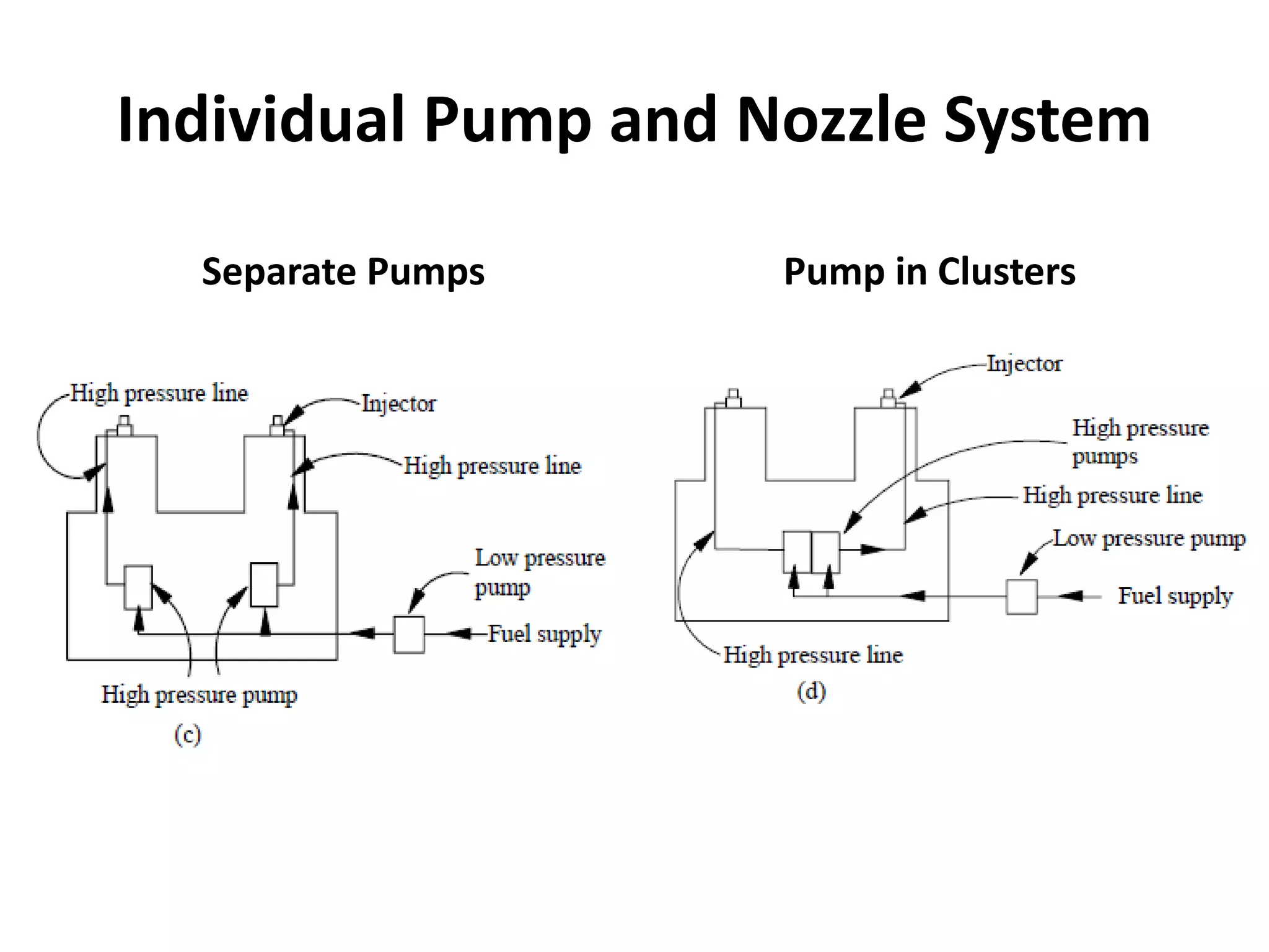
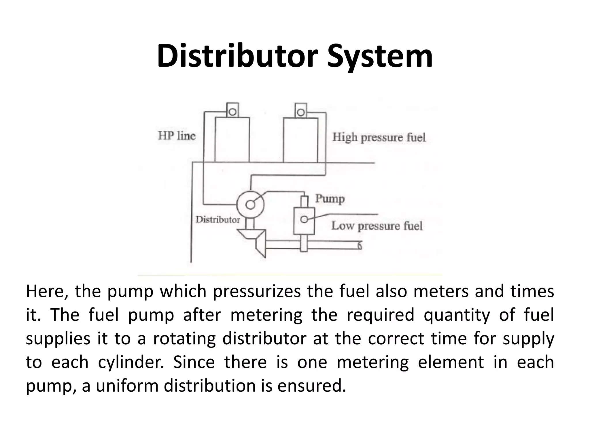
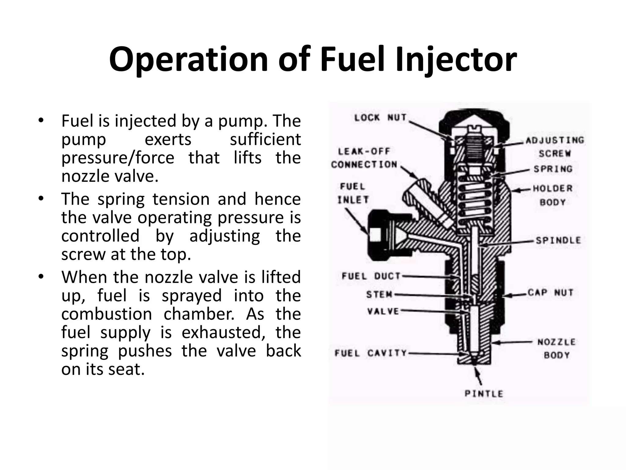
2. Introduction to Fuel Injection System
• Engine Performance i.e. Power Output, economy is
greatly dependent on the effectiveness of the fuel
injection system.
• In case of carburetion, fuel is atomized by processes
relying on the air speed greater than fuel speed at the
fuel nozzle whereas in Fuel-injection the fuel speed at
the point of delivery is greater than the air speed to
atomize the fuel.
• In a fuel injection system, the amount of fuel delivered
into the air stream going to the engine is controlled by
a pump which forces the fuel under pressure.
3. Requirements of Injection Systems
• The fuel injection should occur at the correct moment.
• It should supply the fuel in correct quantity as required
by the varying engine loads.
• The injected fuel must be broken into very fine
droplets.
• The spray pattern should ensure rapid mixing of fuel
and air.
• It should supply equal quantities of metered fuel to all
the cylinders in a multi cylinder engines
• The beginning and the end of injection should be sharp
4. Elements of Fuel Injection System
• Pumping elements: to supply fuel from fuel tank
to cylinder.
• Metering elements: to meter fuel supply as per
load and speed.
• Distribution elements: to divide the metered fuel
equally among the cylinders.
• Timing controls: to adjust the start and the stop
of injection.
• Mixing elements: to atomize and distribute the
fuel within the combustion chamber.
5. Types of Injection system
• Air (Blast) Injection System: In air blast injection
system, fuel is forced into the cylinder by means
of compressed air.
• This method is capable of producing better
atomization and penetration of fuel resulting in
higher brake mean effective pressure.
• This system is little used universally at present,
because it requires a multistage air compressor,
which increases engine weight and reduces brake
power.
6. Types of Injection system (Contd.)
• Solid Injection System: In solid injection, the
liquid fuel is injected directly into the
combustion chamber without the aid of
compressed air. Hence, it is termed as airless
mechanical injection or solid injection.
• Every solid injection system must have
– a pressuring unit (the pump)and
– an atomizing unit (the injector).
7. Types of Solid Injection system
• Depending upon the location of the pumps
and injectors, and the manner of their
operations, solid injection systems may be
further classified as follows:
– Common Rail System
– Unit Injection System
– Individual Pump and Nozzle System
– Distributor System
9. Common Rail System
In this system, a high-pressure pump supplies fuel to a fuel
header as shown. The high-pressure in the header forces the
fuel to each of the nozzles located in the cylinders. At the proper
time, a mechanically operated (by means of push rod and rocker
arm) valve allows the fuel to enter the cylinder through nozzle.
10. Unit Injection System
Here, the pump and nozzle are combined in one housing. Each
cylinder is provided with one of these unit injectors. Fuel is brought
up to the injector by a low-pressure pump, where at the proper
time, a rocker arm activates the plunger and thus injects the fuel
into the cylinder. The quantity of fuel injected is controlled by the
effective stroke of the plunger.
12. Individual Pump and Nozzle System
• In this system, each cylinder is provided with one pump and
one injector.
• This type differs from the unit injector in that the pump and
injector are separated from each other, i.e., the injector is
located on the cylinder, while the pump is placed on the
side of the engine.
• Each pump may be placed close to the cylinder, or may be
arranged in a cluster.
• The high-pressure pump plunger is actuated by a cam, and
produces the fuel pressure necessary to open the injector
valve at the correct time.
• The quantity of fuel injected is again controlled by the
effective stroke of the plunger
13. Distributor System
Here, the pump which pressurizes the fuel also meters and times
it. The fuel pump after metering the required quantity of fuel
supplies it to a rotating distributor at the correct time for supply
to each cylinder. Since there is one metering element in each
pump, a uniform distribution is ensured.
14. Injection Pump
• The main objective of the fuel injection pump is to deliver
accurately a metered quantity of fuel under high pressure
at the correct instant to the injector fitted on each cylinder.
• Two types of pumps are generally used viz., jerk type and
distributor type.
• Fuel delivered by a pump increases with speed while the
opposite is true about the air intake. This results in over
fueling at higher speeds. At low speeds, the engine tends to
stall due to insufficiency of fuel.
• To overcome this, injector pump governors are generally
used. Two types of governors are found in applications viz.,
(a) mechanical governor and (b) pneumatic governor.
15. Fuel Injector
• Quick and complete combustion is ensured by a well
designed fuel injector. By atomizing the fuel into very
fine droplets, it increases the surface area of the
droplets resulting in better mixing and subsequent
combustion. Atomization is done by forcing the fuel
through a small orifice under high pressure. An injector
assembly consists of the following components.
– a needle valve
– a compression spring
– a nozzle
– an injector body
16. Operation of Fuel Injector
• Fuel is injected by a pump. The
pump exerts sufficient
pressure/force that lifts the
nozzle valve.
• The spring tension and hence
the valve operating pressure is
controlled by adjusting the
screw at the top.
• When the nozzle valve is lifted
up, fuel is sprayed into the
combustion chamber. As the
fuel supply is exhausted, the
spring pushes the valve back
on its seat.
17. Nozzle
• The nozzle sprays the liquid fuel. The functions of the
nozzle are: (a) atomization, (b) distribution of fuel to
the required area, (c) non-impingement on the walls,
and (d) no dribbling.
• Note: The fuel striking on the walls decomposes and
produces carbon deposits. This causes smoky exhaust
and increases fuel consumption.
• Note: High injection pressure allows better dispersion
and penetration into the combustion chamber. High air
density in the cylinder gives high resistance to the
droplets. This further causes dispersion.
19. Single Hole Nozzle
The single hole nozzle
requires a high injection
pressure and this type
of nozzle has a
tendency to dribble.
The spray cone angle is
usually narrow, and this
gives poor mixing
unless the velocity is
high.
20. Pintle Nozzle
The pintle nozzle has
been developed to
avoid weak injection
and dribbling. The
spindle is provided with
a pintle capable of
protruding in and out.
Pintle nozzle results in
good atomization and
reduced penetration.
21. Multi-Hole Nozzle
A multi-hole nozzle,
where the number of
holes may vary from 4
to 18, allows a proper
mixing of air and fuel.
The advantage lies with
the ability to distribute
the fuel properly even
with lower air motion
within the chamber.
22. Pintaux Nozzle
• The pintaux nozzle is a
pintle nozzle with an
auxiliary hole drilled
into the nozzle body. At
low speeds, the needle
valve does not lift fully
and most of the fuel is
injected through this
auxiliary hole