Downloaded 1,788 times


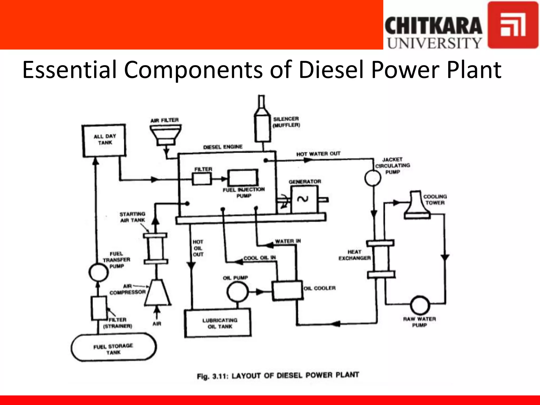


Diesel power plants produce electricity in the range of 2 to 50 MW and are commonly used as central power stations and backup generators. They have advantages over steam power plants such as occupying less space and being more efficient for capacities under 150 MW. However, diesel power plants also have higher operating and maintenance costs compared to steam plants. The key components of a diesel power plant include the diesel engine, air intake and exhaust systems, fuel supply system, starting system, lubrication system, and cooling system. Proper operation and maintenance such as regular engine running and filter servicing is required for good diesel power plant performance.


