Downloaded 719 times
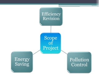
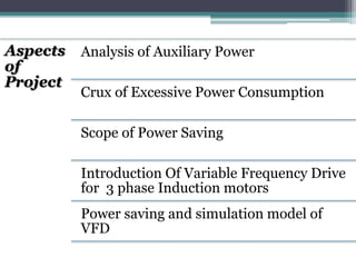

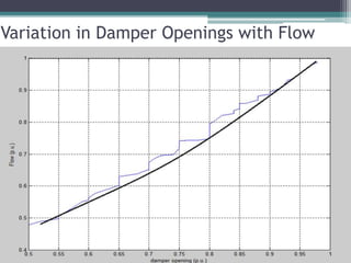

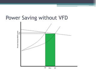
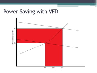
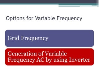
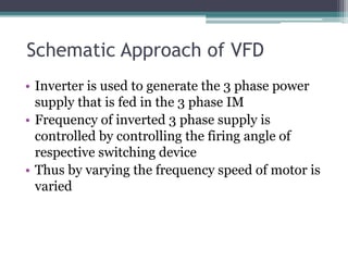
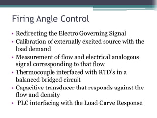
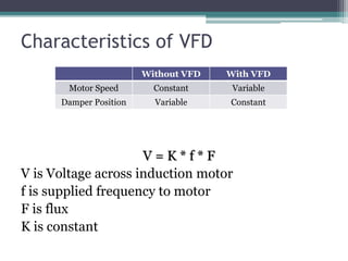
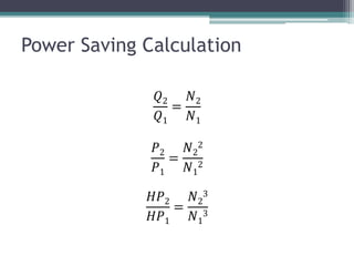

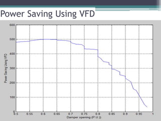
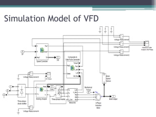
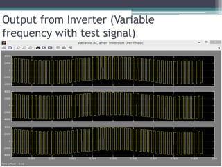
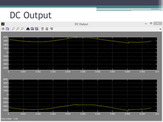
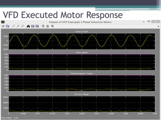


The document discusses the optimization of auxiliary power at thermal power plants through the implementation of Variable Frequency Drives (VFDs) for 3-phase induction motors. It covers aspects such as energy efficiency, pollution control, and the mechanics of draft maintenance. The simulation and calculations provided indicate significant potential for power saving and operational efficiency improvements by utilizing VFD technology.