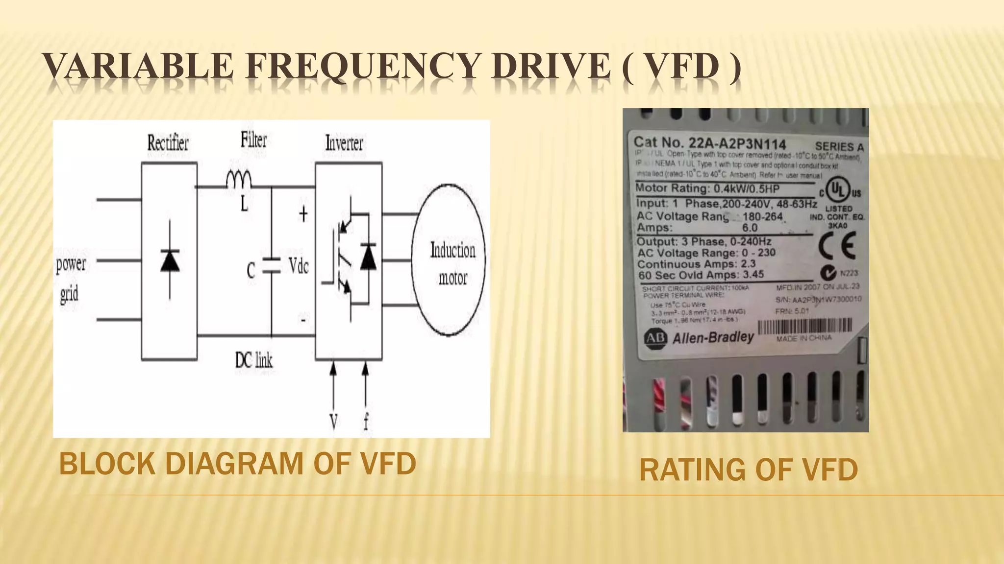
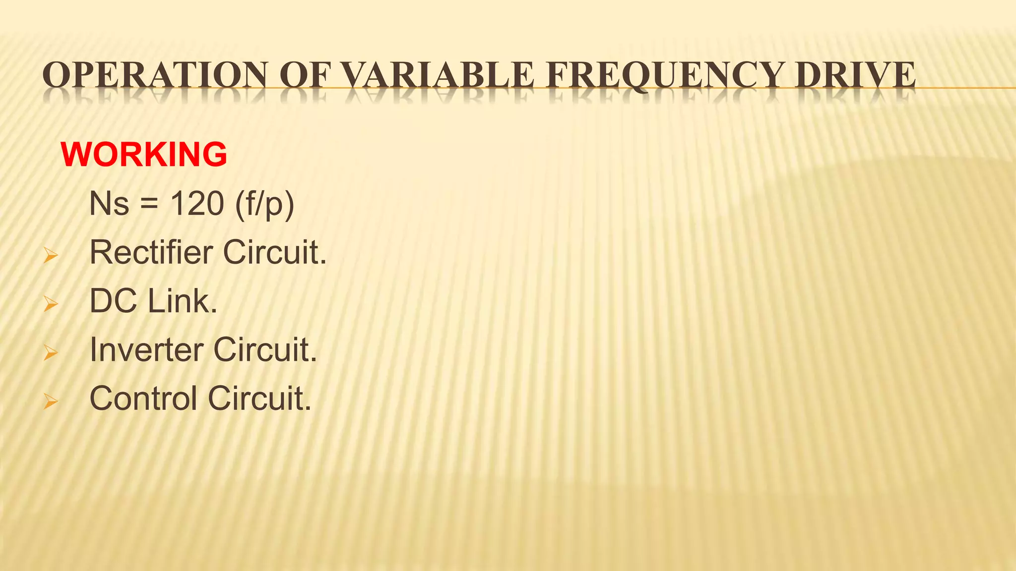
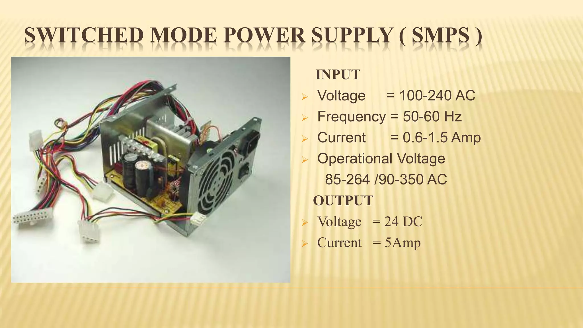
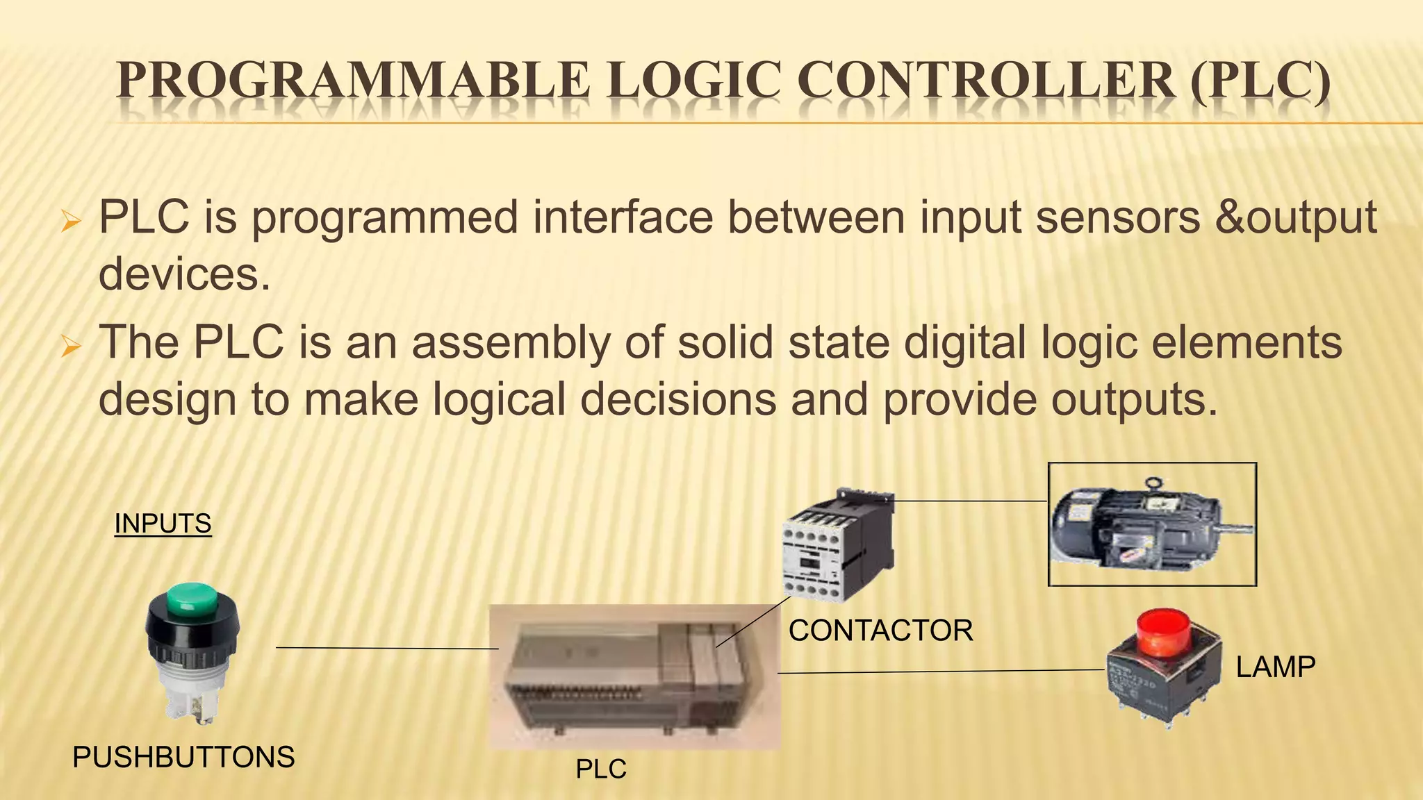
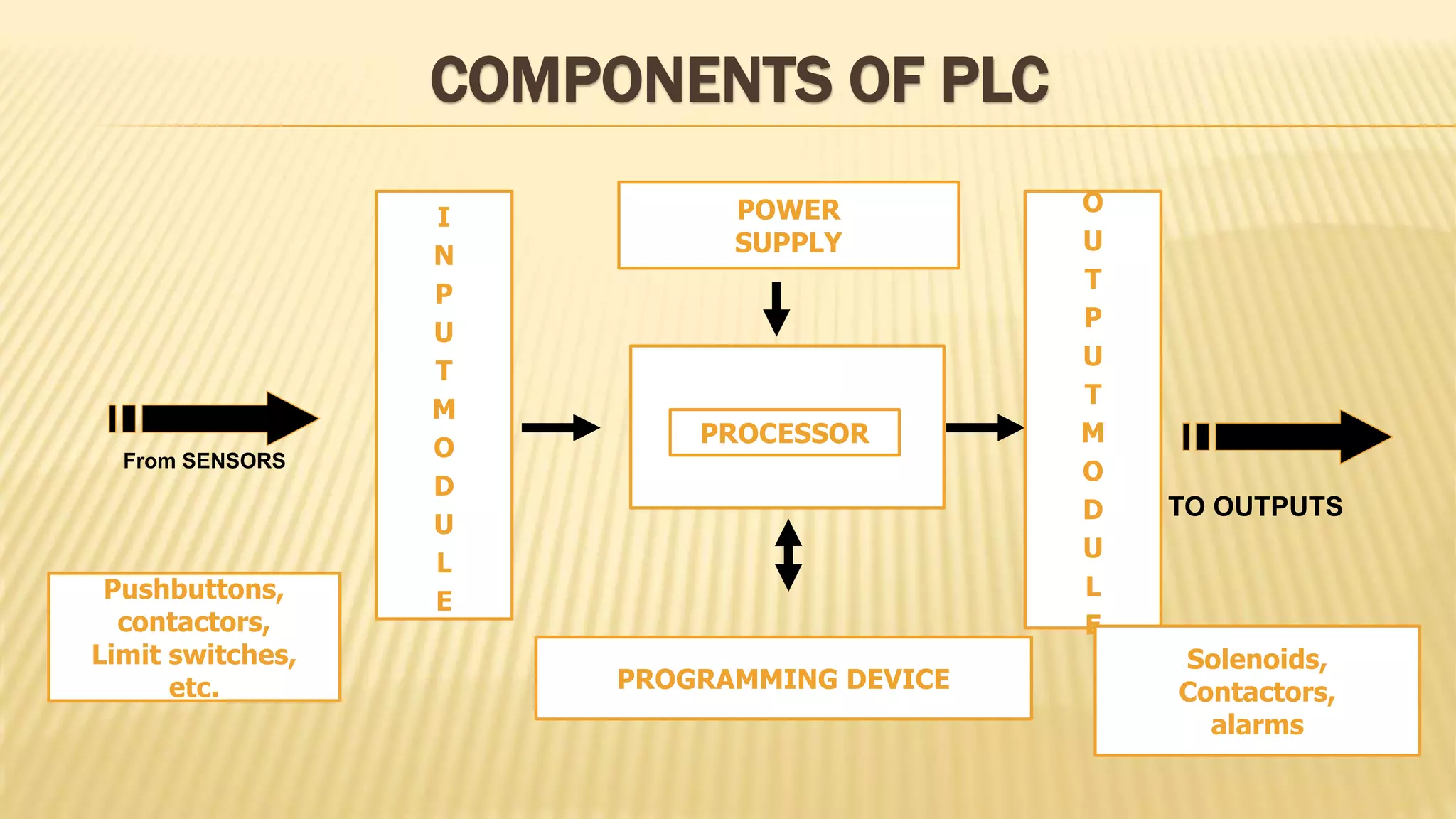
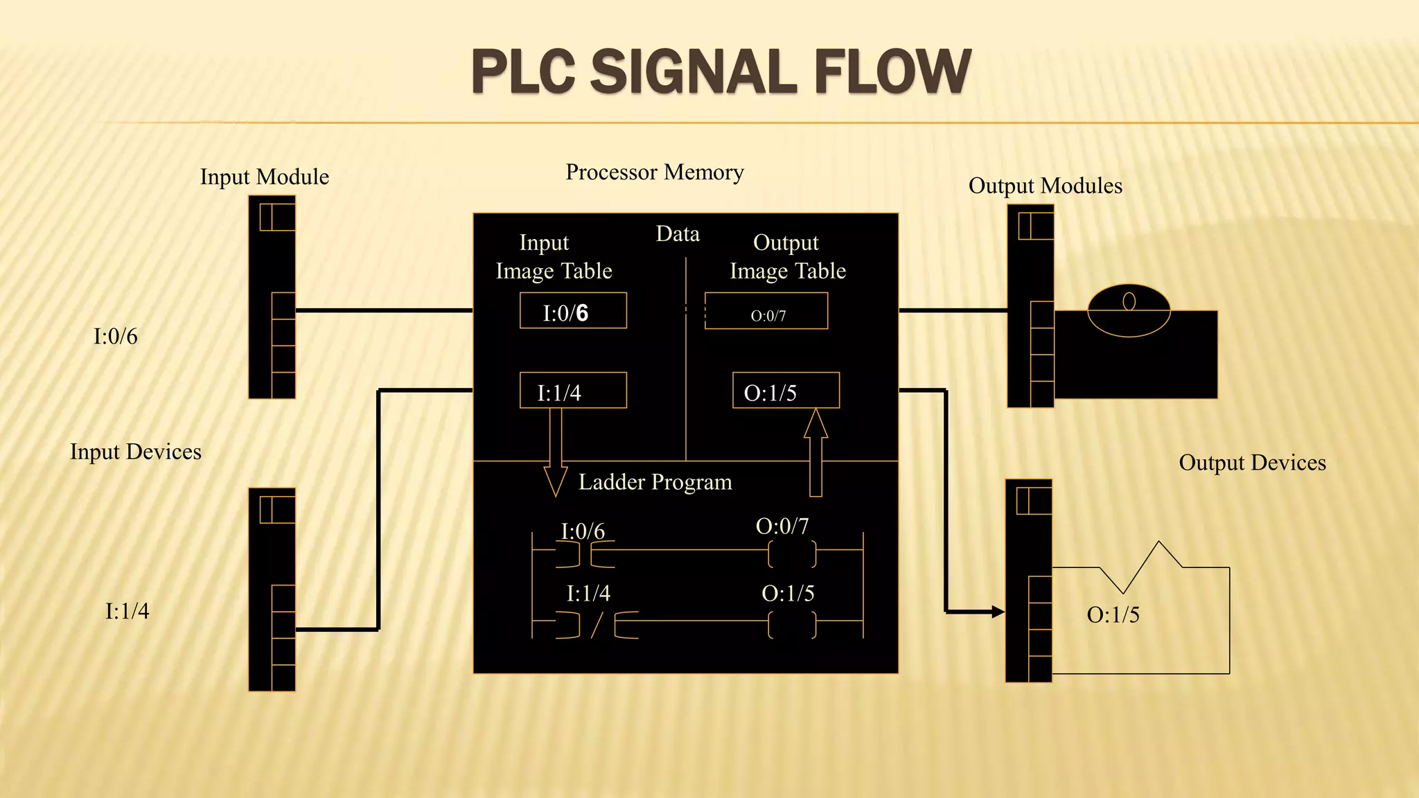
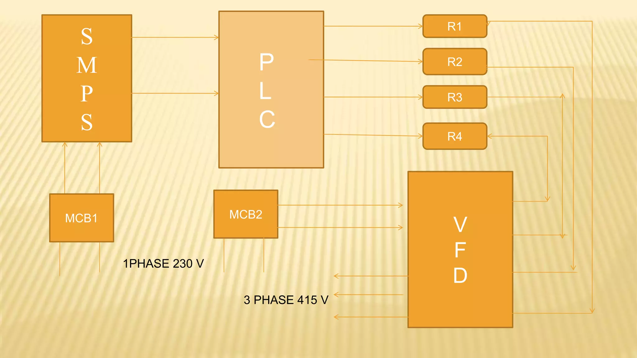
“PLC BASED SPEED
CONTROL OF INDUCTION
MOTOR”
COMPONENT OF SPEED CONTROL OF IM BY PLC
 Miniature Circuit Breaker ( MCB ).
 Relay ( R ).
 Bus Bar ( BB ).
 Variable Frequency Drive ( VFD ).
 Switched Mode Power Supply ( SMPS ).
 Programmable Logic Controller (PLC).
 Induction Motor ( IM ).
VARIABLE FREQUENCY DRIVE ( VFD )
BLOCK DIAGRAM OF VFD RATING OF VFD
OPERATION OF VARIABLE FREQUENCY DRIVE
WORKING
Ns = 120 (f/p)
 Rectifier Circuit.
 DC Link.
 Inverter Circuit.
 Control Circuit.
SWITCHED MODE POWER SUPPLY ( SMPS )
INPUT
 Voltage = 100-240 AC
 Frequency = 50-60 Hz
 Current = 0.6-1.5 Amp
 Operational Voltage
85-264 /90-350 AC
OUTPUT
 Voltage = 24 DC
 Current = 5Amp
SWITCHED MODE POWER SUPPLY ( SMPS )
 Definition
 Advantage
 Disadvantage
 Application
HISTORY OF PLC
The Hydromantic Division of the General Motors Corporation
Specified the design criteria for the first programmable controller
in 1968. Their primary goal was to eliminate the high costs
associated with inflexible, relay-controlled systems.
PROGRAMMABLE LOGIC CONTROLLER (PLC)
 PLC is programmed interface between input sensors &output
devices.
 The PLC is an assembly of solid state digital logic elements
design to make logical decisions and provide outputs.
PLC
INPUTS
LAMP
CONTACTOR
PUSHBUTTONS
TYPES OF PLC
 Compact PLC – inbuilt power supply, processor, i/o’s
 Modular PLC- separate power supply, processor, i/o’s From
Size
 Small-64 I/O’S
 Medium - 1024
 Large - 4096
HARDWARE PART OF PLC
 Central Processing Unit
 Input Modules
 Output Modules
 Power Supply
 Bus system
 Rack(Rail)
COMPONENTS OF PLC
PROCESSOR
POWER
SUPPLY
O
U
T
P
U
T
M
O
D
U
L
E
PROGRAMMING DEVICE
From SENSORS
Pushbuttons,
contactors,
Limit switches,
etc.
Solenoids,
Contactors,
alarms
I
N
P
U
T
M
O
D
U
L
E
TO OUTPUTS
MANUFACTURES OF PLC
 Allen Bradley
 Siemens
 Mitsubishi
 Hitachi
 Delta
ALLEN BRADLEY PLC
PROGRAMMING LANGUAGES OF PLC
 Ladder Logic ( LAD/LD )
 Structured Text ( ST)
 Instruction List ( IL )
 Sequential Function Chart ( SFC )
 Function Block Diagram ( FBD )
O:0/7
PLC SIGNAL FLOW
O:0/7
O:1/5
Output Devices
Output Modules
Processor MemoryInput Module
Input Devices
Ladder Program
O:0/7
O:1/5
I:0/6
I:1/4
O:1/5
1/5
I:0/6 SENSORS O:0/7
6
I:1/4
I:0/6
I:1/4
DataInput
Image Table
Output
Image Table
S
M
P
S
R1
R2
R3
R4
V
F
D
MCB2MCB1
P
L
C
1PHASE 230 V
3 PHASE 415 V
THANKING
YOU

speed control of induction motor using plc and vfd

  • 1.
    “PLC BASED SPEED CONTROLOF INDUCTION MOTOR”
  • 2.
    COMPONENT OF SPEEDCONTROL OF IM BY PLC  Miniature Circuit Breaker ( MCB ).  Relay ( R ).  Bus Bar ( BB ).  Variable Frequency Drive ( VFD ).  Switched Mode Power Supply ( SMPS ).  Programmable Logic Controller (PLC).  Induction Motor ( IM ).
  • 3.
    VARIABLE FREQUENCY DRIVE( VFD ) BLOCK DIAGRAM OF VFD RATING OF VFD
  • 4.
    OPERATION OF VARIABLEFREQUENCY DRIVE WORKING Ns = 120 (f/p)  Rectifier Circuit.  DC Link.  Inverter Circuit.  Control Circuit.
  • 5.
    SWITCHED MODE POWERSUPPLY ( SMPS ) INPUT  Voltage = 100-240 AC  Frequency = 50-60 Hz  Current = 0.6-1.5 Amp  Operational Voltage 85-264 /90-350 AC OUTPUT  Voltage = 24 DC  Current = 5Amp
  • 6.
    SWITCHED MODE POWERSUPPLY ( SMPS )  Definition  Advantage  Disadvantage  Application
  • 7.
    HISTORY OF PLC TheHydromantic Division of the General Motors Corporation Specified the design criteria for the first programmable controller in 1968. Their primary goal was to eliminate the high costs associated with inflexible, relay-controlled systems.
  • 8.
    PROGRAMMABLE LOGIC CONTROLLER(PLC)  PLC is programmed interface between input sensors &output devices.  The PLC is an assembly of solid state digital logic elements design to make logical decisions and provide outputs. PLC INPUTS LAMP CONTACTOR PUSHBUTTONS
  • 9.
    TYPES OF PLC Compact PLC – inbuilt power supply, processor, i/o’s  Modular PLC- separate power supply, processor, i/o’s From Size  Small-64 I/O’S  Medium - 1024  Large - 4096
  • 10.
    HARDWARE PART OFPLC  Central Processing Unit  Input Modules  Output Modules  Power Supply  Bus system  Rack(Rail)
  • 11.
    COMPONENTS OF PLC PROCESSOR POWER SUPPLY O U T P U T M O D U L E PROGRAMMINGDEVICE From SENSORS Pushbuttons, contactors, Limit switches, etc. Solenoids, Contactors, alarms I N P U T M O D U L E TO OUTPUTS
  • 12.
    MANUFACTURES OF PLC Allen Bradley  Siemens  Mitsubishi  Hitachi  Delta
  • 13.
  • 14.
    PROGRAMMING LANGUAGES OFPLC  Ladder Logic ( LAD/LD )  Structured Text ( ST)  Instruction List ( IL )  Sequential Function Chart ( SFC )  Function Block Diagram ( FBD )
  • 15.
    O:0/7 PLC SIGNAL FLOW O:0/7 O:1/5 OutputDevices Output Modules Processor MemoryInput Module Input Devices Ladder Program O:0/7 O:1/5 I:0/6 I:1/4 O:1/5 1/5 I:0/6 SENSORS O:0/7 6 I:1/4 I:0/6 I:1/4 DataInput Image Table Output Image Table
  • 16.
  • 17.