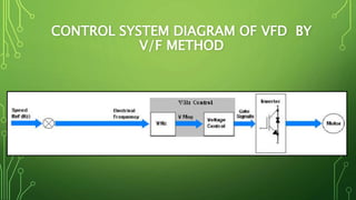
VARIABLE FREQUENCY
DRIVE (VFD) FOR SINGLE
PHASE INDUCTION MOTOR
GROUP # 42405
GROUP MEMBERS:
RASHID NABI (12036) SALAHUDDIN
(12037)
DEEPAK KUMAR (12008) MUHAMMAD SAAD
PROJECT SUPERVISORS
ENGR. SHAHID AHMED
B.E.(ELECTRONICS); DCET, NEDUET, KARACHI
M.ENGG. (INDUSTRIALELECTRONICS), NEDUET,
KARACHI
ENGR. ASGHAR DAUDANI
B.E.(ELECTRICAL), MUET, JAMSHORO
PROJECT WORK IN
CHARGE
ENGR. DR. FARAH HAROON
IN-CHARGE ACADEMICS
B.E. INDUSTRIAL ELECTRONICS, IIEE/NEDUET,
KARACHI
M.ENGG. (ELECTRICAL) NEDUET, KARACHI
PH.D. (TELECOM), ASIAN INSTITUTE OF TECH,
THAILAND
INTRODUCTION TO VFD
•VFD is a type of adjustable speed drive used
in electro mechanical drive systems to
control AC motor speed and torque by varying
motor input frequency and voltage.
•VFD is the combination of Embedded System,
Control System & Power Electronics.
FUNCTIONS & FEATURES OF VFD
• Soft Start
• Wide speed controlling (20Hz to 50Hz).
• Acceleration or Accel-Ramp Rate
• Motor Protection
• Fault Diagnostics
• Bidirectional
INDUCTION MOTOR
• An asynchronous type of an induction motor is an AC electric
motor in which the electric current in the rotor needed to produce
torque is obtained by electromagnetic induction from the magnetic
field of the stator winding.
• An induction motor can therefore be made without electrical
connections to the rotor as are found in universal, DC and
synchronous motors.
• Induction motors are used worldwide in many residential,
commercial, utility and popularly for industrial applications.
• Induction Motors transform electrical energy into mechanical
energy
WHY INDUCTION MOTOR (IM)?
•Robust; No brushes. No contacts on rotor shaft
•High Power/Weight ratio compared to Dc motor
•Lower Cost/Power
•Easy to manufacture
•Almost maintenance-free, except for bearing and
other mechanical parts
DISADVANTAGES
•Essentially a “fixed-speed” machine
•Speed is determined by the input frequency
•To vary its speed need a variable frequency and
variable voltage ratio (v/f)
SYNCHRONOUS SPEED
• The synchronous speed of an induction motor is determined by
the following equation:
• An AC motor's synchronous speed, ns, is the rotation rate of
the stator's magnetic field,
• f = power grid frequency
• p = number of poles
• The only way to change the speed, for the given poles is to vary
the frequency.
BASIC DESIGN OF VFD
•Its basic design consists of four elements:
1)Rectifier
2)DC Bus or Intermediate Circuitry
3)Invertor
4)Control Unit
RECTIFIER
• The working principle of rectifier is changing the incoming
alternating current (AC) supply to direct current (DC).
• The rectifier design will influence the extent to which electrical
harmonics are induced on the incoming supply.
• It can also control the direction of power flow.
DC BUS OR INTERMEDIATE
CIRCUITRY
• The rectified DC supply is then conditioned in the intermediate
circuit, normally by the combination of inductors and
capacitors.
• The DC bus is the true link between the converter and inverter
sections of the drive. Any ripple must be smoothed out before
any transistor switches “on”. If not, this distortion will show up
in the output to the motor.
• The DC bus voltage and current can be viewed through the bus
terminals.
INVERTER
• The inverter converts the rectified and
conditioned DC back into an AC supply of
variable frequency and voltage.
• This is normally achieved by generating a
high frequency pulse width modulated signal
of variable frequency and effective voltage.
• Semiconductor switches are used to create
the output; different types are available, the
most common being the Insulated Gate
Bipolar Transistor (IGBT).
CONTROL UNIT
• The control unit controls the whole operation of the variable
frequency drive
• It monitors and controls the inverter to deliver the correct
output in response to an external control signal.
• In control unit we have a microcontroller Atmega 328p which
performs the logical operation for the switching to generate the
sine pulse width modulation (SPWM) according to given signal.
V/F RATIO OPERATION
• All Variable Frequency Drives maintain the output voltage
– to – frequency (V/f) ratio.
• The voltage has to vary with frequency to keep the
magnetic flux constant.
Where,
N = number of stator turns per phase.
Φm = magnetic flux
• If you didn't reduce the voltage, the flux would increase,
This would cause magnetic saturation resulting in very
high currents.
V/F TABLE
f (Hz) V (volts) v/f (volts/Hz)
50 110 2.2
45 99 2.2
40 88 2.2
35 77 2.2
30 66 2.2
25 55 2.2
20 44 2.2
CONTROL SYSTEM DIAGRAM OF VFD BY
V/F METHOD
SIMULATION & DESIGN OF VFD
THE WAVEFORM OF LOAD OUTPUT &
CONTROLLER OUTPUT
PROBLEMS FACED
• Circuitry didn't uphold 220 volts, and caused to burn out
circuitry.
• Previously we were using MOSFET IRF840 (8A,600v) and
IRFP460 (13A,500v) which couldn't provide the enough initial
current for the motor to rotate the shaft.
• We faced difficulties while setting bootstrap capacitor value
because we can’t get the real value of capacitor from given
formula.
• Faced trouble when we use same controller for the PWM sine
wave generation and rpm calculation through encoder.
SOLUTIONS
• We replaced MOSFET’s with IGBT’s G25N120 (25A,1200V).
• We used step down transformer to reduce voltage from 220v to
110v.
• We used trial and error method to find suitable value for
bootstrap capacitor value.
• We replace our ½ Hp motor with ¼ Hp because our circuitry
can’t provide enough current for ½ Hp motor.
CONCLUSION
• Significant energy savings
• Retrofits (add to something that did not have it when
manufactured)
• Occupy less space
• Better design
• Competitive edge
THANK YOU

Variable Frequency Derive

  • 2.
    VARIABLE FREQUENCY DRIVE (VFD)FOR SINGLE PHASE INDUCTION MOTOR GROUP # 42405 GROUP MEMBERS: RASHID NABI (12036) SALAHUDDIN (12037) DEEPAK KUMAR (12008) MUHAMMAD SAAD
  • 3.
    PROJECT SUPERVISORS ENGR. SHAHIDAHMED B.E.(ELECTRONICS); DCET, NEDUET, KARACHI M.ENGG. (INDUSTRIALELECTRONICS), NEDUET, KARACHI ENGR. ASGHAR DAUDANI B.E.(ELECTRICAL), MUET, JAMSHORO PROJECT WORK IN CHARGE ENGR. DR. FARAH HAROON IN-CHARGE ACADEMICS B.E. INDUSTRIAL ELECTRONICS, IIEE/NEDUET, KARACHI M.ENGG. (ELECTRICAL) NEDUET, KARACHI PH.D. (TELECOM), ASIAN INSTITUTE OF TECH, THAILAND
  • 4.
    INTRODUCTION TO VFD •VFDis a type of adjustable speed drive used in electro mechanical drive systems to control AC motor speed and torque by varying motor input frequency and voltage. •VFD is the combination of Embedded System, Control System & Power Electronics.
  • 5.
    FUNCTIONS & FEATURESOF VFD • Soft Start • Wide speed controlling (20Hz to 50Hz). • Acceleration or Accel-Ramp Rate • Motor Protection • Fault Diagnostics • Bidirectional
  • 6.
    INDUCTION MOTOR • Anasynchronous type of an induction motor is an AC electric motor in which the electric current in the rotor needed to produce torque is obtained by electromagnetic induction from the magnetic field of the stator winding. • An induction motor can therefore be made without electrical connections to the rotor as are found in universal, DC and synchronous motors. • Induction motors are used worldwide in many residential, commercial, utility and popularly for industrial applications. • Induction Motors transform electrical energy into mechanical energy
  • 7.
    WHY INDUCTION MOTOR(IM)? •Robust; No brushes. No contacts on rotor shaft •High Power/Weight ratio compared to Dc motor •Lower Cost/Power •Easy to manufacture •Almost maintenance-free, except for bearing and other mechanical parts
  • 8.
    DISADVANTAGES •Essentially a “fixed-speed”machine •Speed is determined by the input frequency •To vary its speed need a variable frequency and variable voltage ratio (v/f)
  • 9.
    SYNCHRONOUS SPEED • Thesynchronous speed of an induction motor is determined by the following equation: • An AC motor's synchronous speed, ns, is the rotation rate of the stator's magnetic field, • f = power grid frequency • p = number of poles • The only way to change the speed, for the given poles is to vary the frequency.
  • 10.
    BASIC DESIGN OFVFD •Its basic design consists of four elements: 1)Rectifier 2)DC Bus or Intermediate Circuitry 3)Invertor 4)Control Unit
  • 11.
    RECTIFIER • The workingprinciple of rectifier is changing the incoming alternating current (AC) supply to direct current (DC). • The rectifier design will influence the extent to which electrical harmonics are induced on the incoming supply. • It can also control the direction of power flow.
  • 12.
    DC BUS ORINTERMEDIATE CIRCUITRY • The rectified DC supply is then conditioned in the intermediate circuit, normally by the combination of inductors and capacitors. • The DC bus is the true link between the converter and inverter sections of the drive. Any ripple must be smoothed out before any transistor switches “on”. If not, this distortion will show up in the output to the motor. • The DC bus voltage and current can be viewed through the bus terminals.
  • 13.
    INVERTER • The inverterconverts the rectified and conditioned DC back into an AC supply of variable frequency and voltage. • This is normally achieved by generating a high frequency pulse width modulated signal of variable frequency and effective voltage. • Semiconductor switches are used to create the output; different types are available, the most common being the Insulated Gate Bipolar Transistor (IGBT).
  • 14.
    CONTROL UNIT • Thecontrol unit controls the whole operation of the variable frequency drive • It monitors and controls the inverter to deliver the correct output in response to an external control signal. • In control unit we have a microcontroller Atmega 328p which performs the logical operation for the switching to generate the sine pulse width modulation (SPWM) according to given signal.
  • 15.
    V/F RATIO OPERATION •All Variable Frequency Drives maintain the output voltage – to – frequency (V/f) ratio. • The voltage has to vary with frequency to keep the magnetic flux constant. Where, N = number of stator turns per phase. Φm = magnetic flux • If you didn't reduce the voltage, the flux would increase, This would cause magnetic saturation resulting in very high currents.
  • 16.
    V/F TABLE f (Hz)V (volts) v/f (volts/Hz) 50 110 2.2 45 99 2.2 40 88 2.2 35 77 2.2 30 66 2.2 25 55 2.2 20 44 2.2
  • 17.
    CONTROL SYSTEM DIAGRAMOF VFD BY V/F METHOD
  • 18.
  • 19.
    THE WAVEFORM OFLOAD OUTPUT & CONTROLLER OUTPUT
  • 20.
    PROBLEMS FACED • Circuitrydidn't uphold 220 volts, and caused to burn out circuitry. • Previously we were using MOSFET IRF840 (8A,600v) and IRFP460 (13A,500v) which couldn't provide the enough initial current for the motor to rotate the shaft. • We faced difficulties while setting bootstrap capacitor value because we can’t get the real value of capacitor from given formula. • Faced trouble when we use same controller for the PWM sine wave generation and rpm calculation through encoder.
  • 21.
    SOLUTIONS • We replacedMOSFET’s with IGBT’s G25N120 (25A,1200V). • We used step down transformer to reduce voltage from 220v to 110v. • We used trial and error method to find suitable value for bootstrap capacitor value. • We replace our ½ Hp motor with ¼ Hp because our circuitry can’t provide enough current for ½ Hp motor.
  • 22.
    CONCLUSION • Significant energysavings • Retrofits (add to something that did not have it when manufactured) • Occupy less space • Better design • Competitive edge
  • 23.