Electrical, Electronics and Computer Engineering,
Information Engineering and Technology,
Mechanical, Industrial and Manufacturing Engineering,
Automation and Mechatronics Engineering,
Material and Chemical Engineering,
Civil and Architecture Engineering,
Biotechnology and Bio Engineering,
Environmental Engineering,
Petroleum and Mining Engineering,
Marine and Agriculture engineering,
Aerospace Engineering.
young call girls in Rajiv Chowk🔝 9953056974 🔝 Delhi escort Service
International Journal of Engineering Research and Development
1. International Journal of Engineering Research and Development
e-ISSN: 2278-067X, p-ISSN: 2278-800X, www.ijerd.com
Volume 10, Issue 4 (April 2014), PP.94-103
94
Simulation of PWM inverter for VFD application Using
MATLAB
1
Krupa Gandhi, K.L.Mokariya2
, Deepa Karvat3
1
M.E.(electrical)Parul Institute of Engg.-Baroda.
2
Asst. Prof, Dr S & SS Gandhi, Government Engg. College-Surat.
3
Asst. Prof, Parul Institute of Engg.-Baroda.
Abstract:- In this paper, at first, operating principle of variable frequency drive is explained. Different
components of VFD are explained. Suitability of VFD for different types of load is also explained. Concept of
PWM inverter for VFD is explained and analysis of PWM inverter for VFD is done.
Keywords:- Operating principle of VFD; PWM; Modulation Index; Carrier Frequency; variable torue load.
I. INTRODUCTION
The speed of the motor can be changed by various methods such as changing poles, controlling
voltage, connecting resistance in rotor circuit etc., but most efficient method is changing the supply frequency
and voltage to the motor. The variable frequency drive (VFD) varies the frequency and hence varies the speed of
the motor as per the requirements of the load. Speed control of AC/DC motors can be achieved by the variable
speed drive (VSD) unit. DC drives are used for special applications such as few low-speed, low-to-medium
power applications because of problems with mechanical commutation and expensive at large size. Usually AC
drives especially squirrel cage induction motor is widely used due to its rugged construction, easy installation
and maintenance, higher efficiency and low cost.
II. OPERATING PRINCIPLE
Fig 1 Power conversion unit for VFD
Fig 1 shows the power conversion unit in PWM drive. In this type of drive, a diode bridge rectifier
provides the intermediate DC circuit voltage. in the intermediate DC circuit, Dc voltage is filtered in low pass
filter. Output voltage and frequency controlled electronically by controlling the width of pulses of voltage to
motor.
The variable frequency drive (VFD) converts the supply frequency and voltage to the required
frequency and voltage to drive a motor. Hence, VFD converts the supply frequency and voltage to the frequency
and voltage required to drive a motor at a desired speed other than its rated speed.
The synchronous speed of an induction motor is given by the equation as:
p
f
Ns
120
The gap between synchronous speed and running speed is called the slip.
100%
Ns
NNs
S
Running speed, N = Ns (1-S)
2. Simulation of PWM inverter for VFD application Using MATLAB
95
= S
p
f
1
120
So, .fN
Thus the running speed of induction is directly proportional to the supply frequency. If the frequency
changes the actual running speed of motor also changes. VFD controls the frequency from supply and it is
adjusted to the present requirement.
The basic functions of variable speed drive are to control the frequency of the supply to the motor and
power transfer efficiently from supply mains to the motor drive.
III. COMPONENTS OF VFD
The variable speed drive consists of rectifier, inverter and control components.
A.Rectifier: A full-wave, solid-state rectifier converts three-phase 50 Hz power from a standard 220, 440 or
higher utility supply to either fixed or adjustable DC voltage. The system may include transformers if higher
supply voltages are used.
Figure 1 Rectifier Circuit
B.Inverter: Electronic switches - power transistors or thyristors - switch the rectified DC on and off, and
produce a current or voltage waveform at the desired new frequency. The amount of distortion depends on the
design of the inverter and filter.
Figure 2 Inverter Circuit
C.Control system: An electronic circuit receives feedback information from the driven motor and
adjusts the output voltage or frequency to the selected values. Usually the output voltage is regulated to produce
a constant ratio of voltage to frequency (V/Hz). Controllers may incorporate many complex control functions.
3. Simulation of PWM inverter for VFD application Using MATLAB
96
Figure 3 VFD System
Converting DC to variable frequency AC is accomplished using an inverter. Most currently available
inverters use pulse width modulation (PWM) because the output current waveform closely approximates a sine
wave. Power semiconductors switch DC voltage at high speed, producing a series of short-duration pulses of
constant amplitude. Output voltage is varied by changing the width and polarity of the switched pulses. Output
frequency is adjusted by changing the switching cycle time. The resulting current in an inductive motor
simulates a sine wave of the desired output frequency (see Figure below). The high-speed switching of a PWM
inverter results in less waveform distortion and, therefore, lower harmonic losses.
Figure 4 Pulse width modulations
D.Charging Resistor
The charging resistor is included in the DC bus to provide current limiting during the initial power up
stages of the VFD. When a fully discharged VFD is switched on to the power supply, the capacitors on the DC
bus are seen by the power supply as a very low impedance load. If the design does not include a charging
resistor, the current surge magnitude would be so high that the input bridge can be damaged, or require up-rating
far beyond that required for normal running.
Figure 5 VFD Construction
4. Simulation of PWM inverter for VFD application Using MATLAB
97
E.AC Line Choke
The AC Line choke design provides some smoothing on the DC bus and reduces the amount of ripple
current that must be tolerated by the main capacitors. This has an effect of extending the life of these
components. The choke provides a limiting function to the magnitude of the DC bus current during normal
operation. These results in an improved overall power factor of the VFD and reduced harmonic currents flowing
in the power distribution network.
F. VFD Voltage to Frequency Ratio
When connected to a VFD, motor speed is no longer fixed by supply frequency, since the VFD can
vary its output frequency. Under perfect conditions, at zero speed the terminal voltage would also be zero.
Obviously if this was the case then the motor would produce zero torque and in many cases this would be
unacceptable. Also at very low speeds the motor winding appears more like a resistive load than an inductive
load. To overcome this problem with a general purpose VFD, a degree of fixed voltage boost is applied at zero
speed. As the motor accelerates, a proportion of fixed boost is replaced by normal V/F ratio until, at some speed
above zero, governed by the amount of fixed boost applied, all boost is replaced by the normal V/F ratio. If an
excessive amount of fixed boost is applied, the motor can become overheated due to over fluxing.
Figure .6 VFD Voltages to Frequency Ratio
IV. SELECTION OF VARIABLE SPEED DRIVE
Type of Load
It is very important to know the type and characteristics of the load that is driven by the motor before
selecting the variable speed drive.
A. For constant Torque Load
Figure 7 Constant Torque Load
A constant torque load is characterized as one in which the torque is constant regardless of speed. As a
result the horsepower requirement is directly proportional to the operating speed of the application and varied
directly with speed. Since torque is not a function of speed, it remains constant while the horsepower and speed
vary proportionately. Typical examples of constant torque applications include: Conveyors, Extruders, Mixers,
5. Simulation of PWM inverter for VFD application Using MATLAB
98
Positive displacement pumps and compressors. Some of the advantages VFDs offer in constant torque
applications include precise speed control and starting and stopping with controlled acceleration/deceleration.
B. For constant Horsepower load
Figure .8 Constant Horsepower Load
The second type of load characteristic is constant power. In these applications the torque requirement
varies inversely with speed. As the torque increases the speed must decrease to have a constant horsepower load.
The relationship can be written as:
Power = speed x torque x constan
Examples of this type of load would be a lathe or drilling and milling machines where heavy cuts are
made at low speed and light cuts are made at high speed. These applications do not offer energy savings at
reduced speeds.
C. For variable torque load
Figure 9 Variable Torque Load
The third type of load characteristic is a variable torque load. Examples include centrifugal fans,
blowers and pumps. The use of a VFD with a variable torque load may return significant energy savings.
In these applications:
• Torque varies directly with speed squared
• Power varies directly with speed cubed
This means that at half speed, the horsepower required is approximately one eighth of rated maximum.
6. Simulation of PWM inverter for VFD application Using MATLAB
99
V. CONCEPT OF PWM FOR VFD.
Fig 10 PWM Signal Generation
Above figure shows the concept of PWM for VFD,PWM techniques require switching the inverter
power device (transistor and IGBT) on and off many times in order to generate the proper RMS voltage levels.
This switching scheme requires more complex regulator then the VVI. With the use of a
microprocessor, these complex regulation functions are effectively handled. Combining a triangular wave and
sine wave produces output voltage waveform. The triangular signal is the carrier or switching frequency of
inverter. The modulation generator produces a sine wave signals that determines the width of pulses, and
therefore the RMS voltage output of inverter.
Ac drives that use a PWM types schemes have varying level of performance based on control algorithms.
There are four basics types of control for AC drive today. These are volts per hertz, sensor less vector
control, flux vector control and field oriented control.
1. V/Hz control is basic control method, providing a variable frequency drive application like pump and
fan. It provide fair speed and torque control, at a reasonable cost.
2. Sensorless vector control provides better speed regulation and ability to produce high starting torque.
3. Flux vector control provides more precise speed and torque with dynamic response.
4. Field oriented control drive provides best speed and torque control available for AC motor. It provides
DC performance for AC motors and is well suited for typical DC application.
VI. ANALYSIS OF PWM INVERTER USING VFD
Fig 11 Analysis of PWM Inverter Using VFD
7. Simulation of PWM inverter for VFD application Using MATLAB
100
Above fig shows a usefulness of MATLAB to illustrate pulse width modulation technique for inverter
application used for VFD application. In this matlab simulation we have use discrete 3-phase PWM generator,
the discrete 3-phase PWM generator blocks generates pulses for carrier base PWM converters. The block is used
to fire the IGBT of 2 level or 3 level converters. Using a single bridge or two bridge connected in twin
configuration vector its output of P1 & P2 either 6 pulses(2 level) or 12 pulses (3 level).
In our case we have use output P1 when operating in single bridge configuration for 6-pulses.
Carrier frequency= 900 Hz.
Modulation Index=0.9.
Table 1.1 Design Values for Proposed Matlab Mode Table 1.2 Design Values for Asynchronous Machine
Sr no Parameter Value
1 Stator resistance and
inductance
1.405Ω ,
0.005839H
2 Rotor resistance and
inductance
1.395Ω,
0.005839H
3 Mutual inductance 0.1722 Ω
4 Inertia 0.0131kg-𝒎 𝟐
5 Friction factor 0.002985
6 Poles pair 2
7 Initial condition 1 0 0 0 0 0 0 0
Above table shows design values for motor parameters used in inverter application for proposed
variable frequency drive.
SR NO MODULATION INDEX VOLTAGE
1 0.1 240
2 0.2 300
3 0.3 310
4 0.4 330
5 0.5 370
6 0.6 400
7 0.7 442
8 0.8 470
9 0.9 480
Table 1.3 Effect of Modulation Index on Voltage
Above table show that when modulation Index increaes rms voltage will increse in the block of discrete
3-phase pwm generator and waveform also shown.
Table 1.4 Effect of Frequency on speed
Above table show that when frequency increaes speed will increse in the block of discrete 3-phase
pwm generator and waveform also shown.
Power 5.4 Hp
Voltage 400v
Frequency 50 Hz
Synchronous speed 1430 rpm
Snubber resistance and
capacitance
1e5,inf
Inverter IGBT
Rectifier Thyristor bridge
Inductance(dc link) 200e-6
Capacitance(dc link) 5000e-6
SR NO FREQUENCY SPEED
1 5 270
2 10 350
3 15 458
4 20 636
5 30 887
6 35 955
7 40 1242
8 45 1273
9 50 1433
8. Simulation of PWM inverter for VFD application Using MATLAB
101
VII .WAVEFORM ANALYSIS
Fig 12 voltage waveform for Modulation Index 0.9
Fig 13 voltage waveform for Modulation Index 0.1
Above waveform of fig 12 & 13 shows that when modulation index increases rms voltage will increase.
Fig 14 speed waveform for frequency at 25 Hz
Fig 15 speed waveform for frequency at 50 Hz
9. Simulation of PWM inverter for VFD application Using MATLAB
102
Above waveform of fig 14 & 15 shows that when frequency increases speed will increase.
Fig 16 waveform of voltage, speed, current and torque.
Above fig shows the waveform of voltage, speed, current and torque of variable frequency drive.
Fig 17 THD of current waveform
Fig 18 THD of voltage waveform
10. Simulation of PWM inverter for VFD application Using MATLAB
103
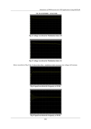
Fig 19 voltage waveform
VIII. CONCLUSION
In this paper 6 pulse PWM inverter is studied for induction motor which is used for variable frequency
drives. The voltage is increase by increasing modulation index and speed also increase when frequency will
increase. The effect on stator voltage; current, speed and torque is studied. Due to inherent control from inverter
itself using pwm techniques voltage is sinusoidal so harmonics are eliminated without using any sought of filter
circuit for suppressing harmonics and it will be advantageous when these pwm techniques is used for high rating
drives where cost of filter is not justified.
REFERENCES
[1]. “ANALYSIS OF VARIABLE FREQUENCY THREE PHASE INDUCTION MOTOR DRIVE” Thida
Win, Nang Sabai, and Hnin Nandar Maung. World Academy of Science, Engineering and Technology
18 2008.
[2]. “ENERGY EFFICIENT INDUSTRIAL MOTORS” Gajendra Singh, N K Sharma, P Tiwari,
International Journal of Engineering Science and Technology Vol. 2(12), 2010.
[3]. “Energy use, energy savings and emission analysis in the Malaysian rubber producing industries” , R.
Saidur a,, S. Mekhilef ,–applied energy Elsevier journal, 2010.
[4]. “ENERGY AUDIT IN INDUSTRY-A CASE STUDY OF CENTRIFUGAL PUMPS” R.M. Holmukhe
& K.D.Deshpande, i-COST Electronics & communication proceedings 13-15 jan-2011.
[5]. “ VARIABLE FREQUENCY DRIVE” Jigar N. Mistry , Hetal D. Solanki, Tejas M. Vala Research
Expo International Multidisciplinary Research Journal Volume – II , Issue – III September – 2012.
[6]. “RESEARCH TO STUDY VARIABLE FREQUENCY DRIVE AND IT’S ENERGY SAVINGS.”
Tamal Aditya International Journal of Science and Research (IJSR), India Online ISSN: 2319-
7064Volume 2 Issue 6, June 2013.
[7]. BOOK “Energy efficiency in electrical system in volume-II by V.K.Gaudani.