Downloaded 158 times
![Voltage equations
Flux equations
Where,
Synchronous Speed , or Speed of RMF
Rotor Speed
s
r
[ ] [ ]
[ ] [ ]
sdq s sdq sr rdq
rdq r rdq sr sdq
L i M i
L i M i
[ ]
[ ] [ ]
[ ]
[ ] [ ]
sabc
sabc s sabc
rabc
rabc r rabc
d
V R i
dt
d
V R i
dt
Basic Voltage Equations
( )
( )
sd
sd s sd s sq
sq
sq s sq s sd
rq
rd r rd s r rq
rq
rq r rq s r rd
d
V R i
dt
d
V R i
dt
d
V R i
dt
d
V R i
dt
](https://image.slidesharecdn.com/inductionmotormodellingandapplications-161130095101/75/Induction-motor-modelling-and-applications-8-2048.jpg)
![1
[ ]
[ ]
( )
[ ]
( )
sd sd rd s sd s
sr s sq sr rq
s s s s
sq sq s sq rqsr s
s sd sr rd
s s s s
rd rd sr sd s rr
rd r rq sr sq
r r r r
rq rq r rq sqsr s r
r r r
di V di R i
M L i M i
dt L L dt L L
di V R i diM
L i M i
dt L L L dt L
di V M diR
i L i M i
dt L L L dt L
di V R i diM
dt L L L dt L
[ ]r rd sr sd
r
L i M i
Final equations](https://image.slidesharecdn.com/inductionmotormodellingandapplications-161130095101/75/Induction-motor-modelling-and-applications-9-2048.jpg)


![REFERENCES
[1]Norman S Nise, “Control Systems Engineering”, Wiley Student Edition, 5th Edition, 2009
[2] Joseph J Distefano III and other, “Feedback and Control Systems”, Schaum’s Outlines,
TMH, 2ndEdition, 2007
[3] Ashfaq Hussain, “Electrical Machines”, Dhanpat Rai Publications
[4] Katsuhiko Ogata, “Modern Control Engineering”, PHI,5th Edition, 2010
[5] Fouad Giri “AC electric motors control”: advanced design techniques and applications ,
John Wiley & Sons, Ltd. 2013
[6] Chee-Mun ong , “Dynamic simulation of electric machinary”,using matlab/simulink
[7] Krstic M, Kanellakopoulos I, and Kokotovic P (1995) “Nonlinear and Adaptive Control
Design”. John Wiley & Sons. Leonard W (2001) “Control of Electrical Drives”. Springer,
New York.
[8] Novotnak RT, Chiasson J, and Bodson M (1999) High performance mtion control of an
induction motor with magnetic saturation, IEEE Transactions on Control Systems
Technology, 7, 315–327.
[9] Astolfi A, Karagiannis D, and Ortega R (2007) “Nonlinear and Adaptive Control with
Applications”. Springer. Besanc¸on G (2007) “Nonlinear Observers and Applications”.
Springer
[10] Khalil HK and Strangas EG (1996) Robust speed control of induction motors using
position and current measurement. IEEE Transactions on Automatic Control, 41, 1216–
1220.
[11] Dorf & Bishop- Pearson education, “Modern control systems”, 11th Edition 2008.](https://image.slidesharecdn.com/inductionmotormodellingandapplications-161130095101/75/Induction-motor-modelling-and-applications-30-2048.jpg)

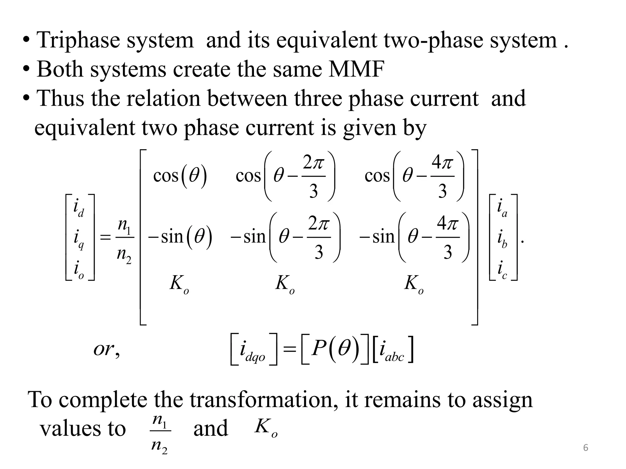
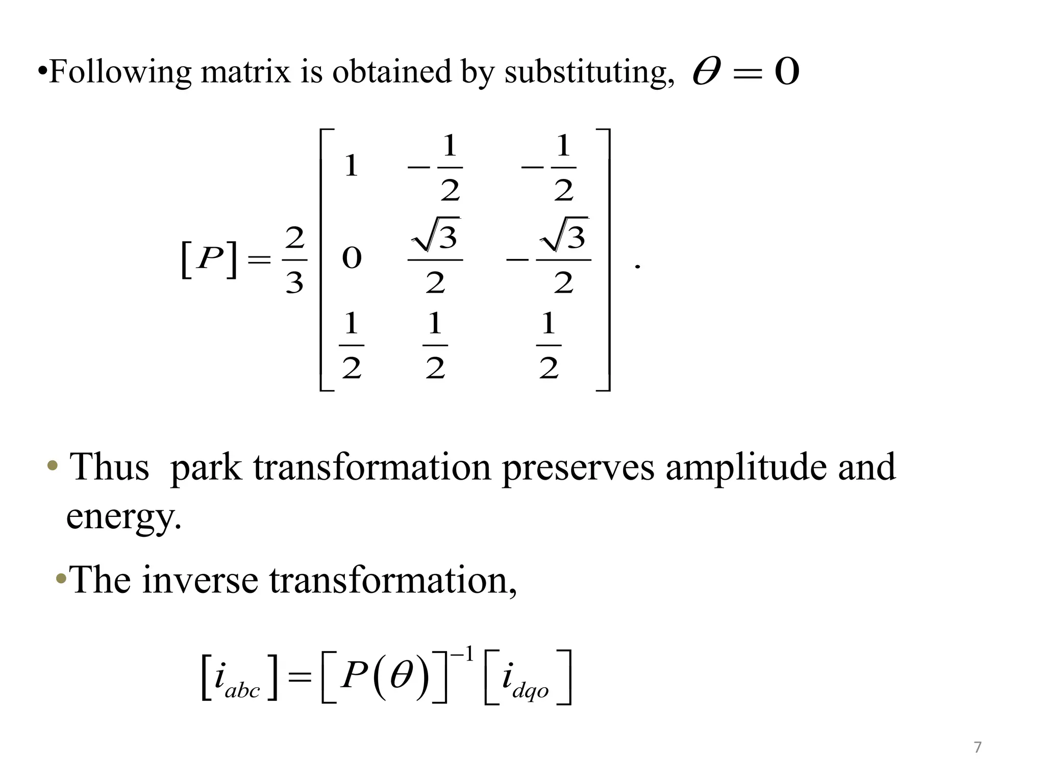
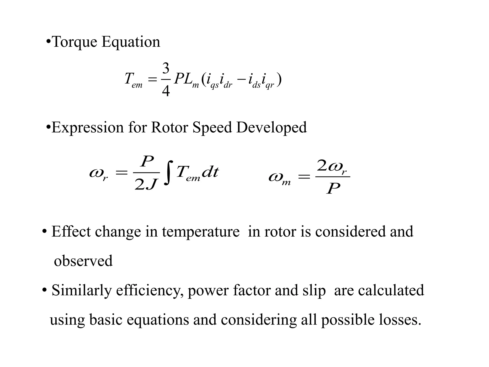
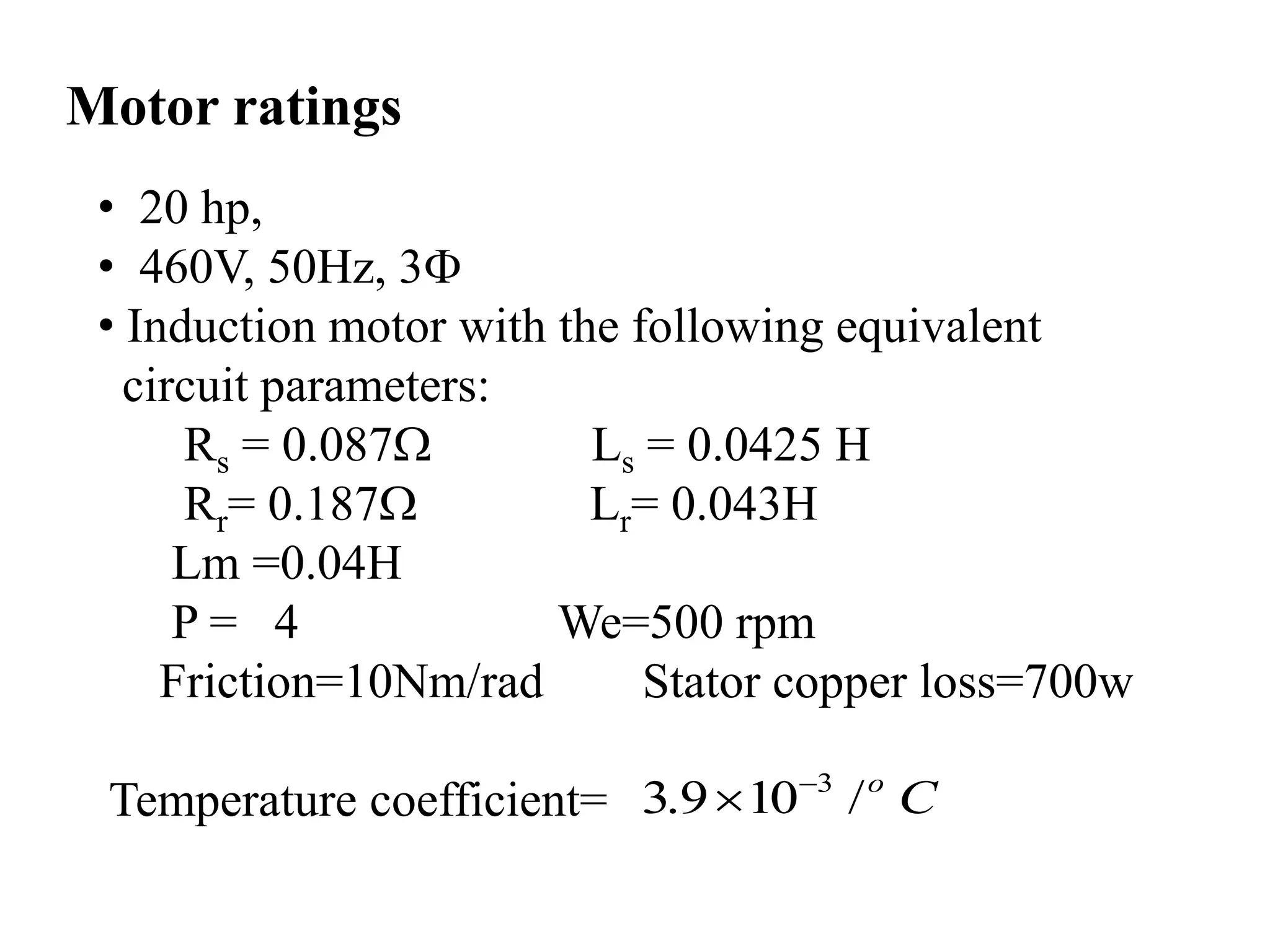
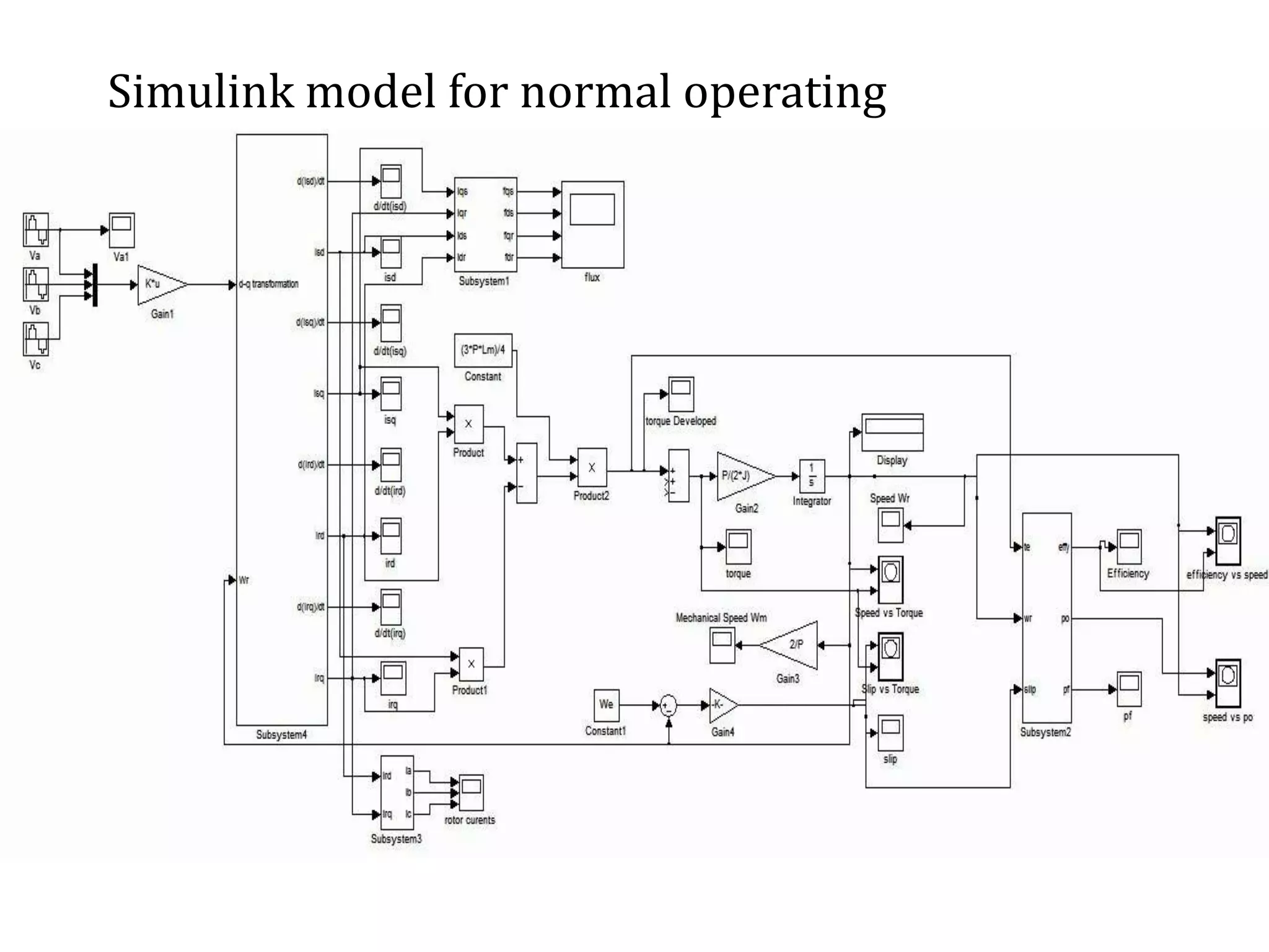
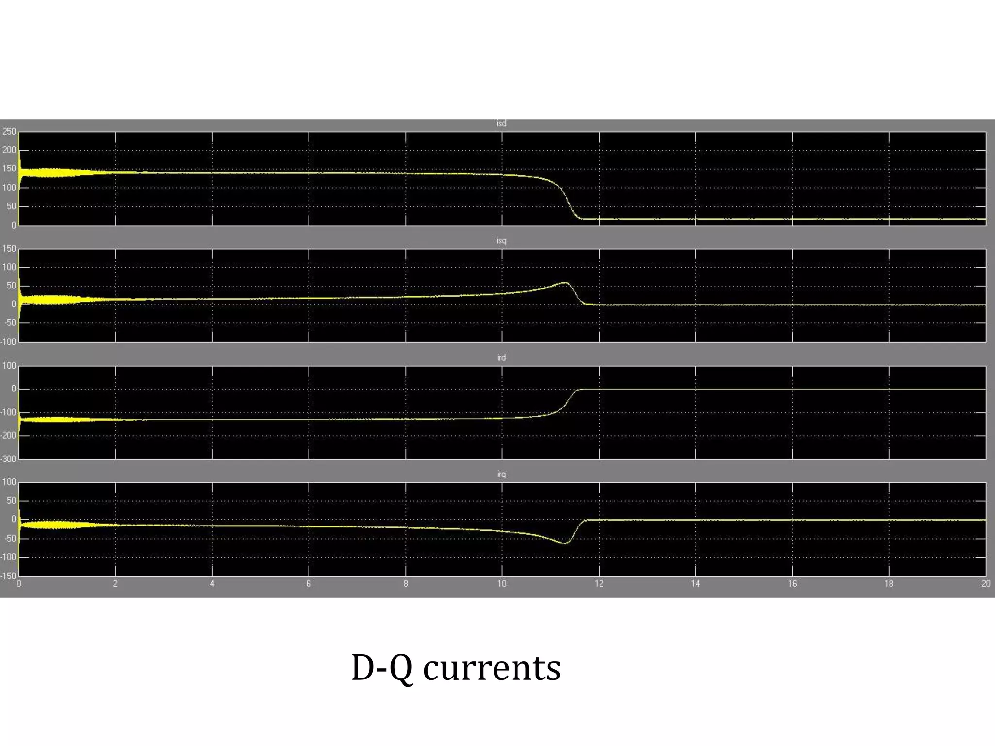
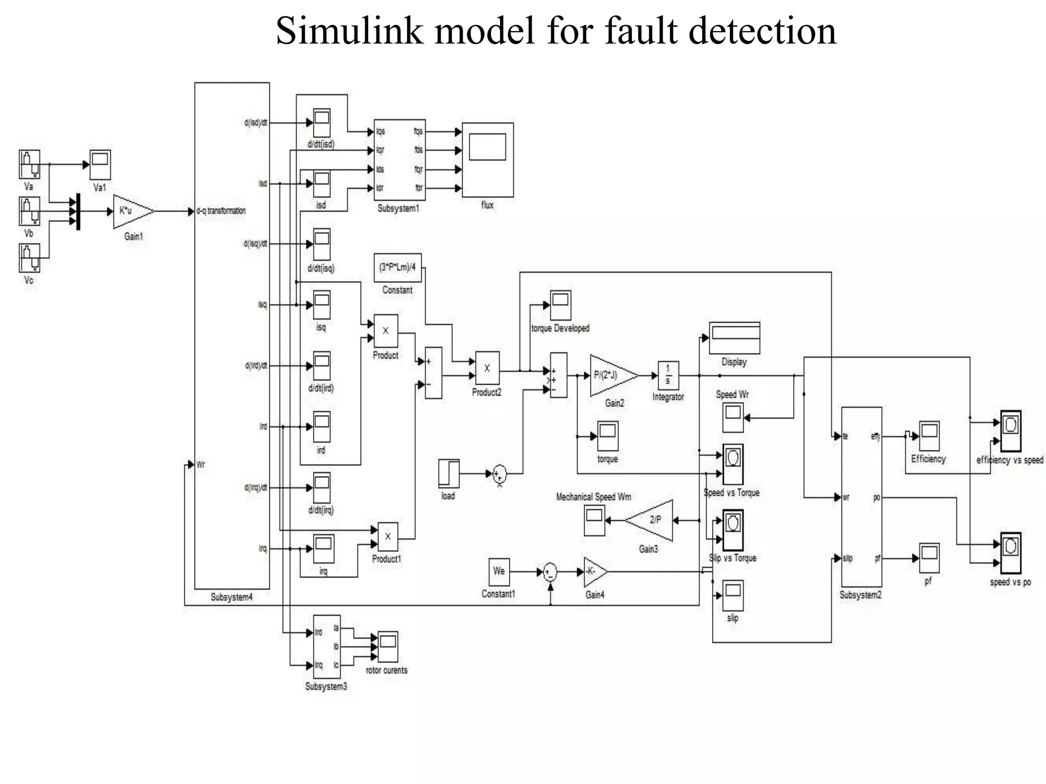
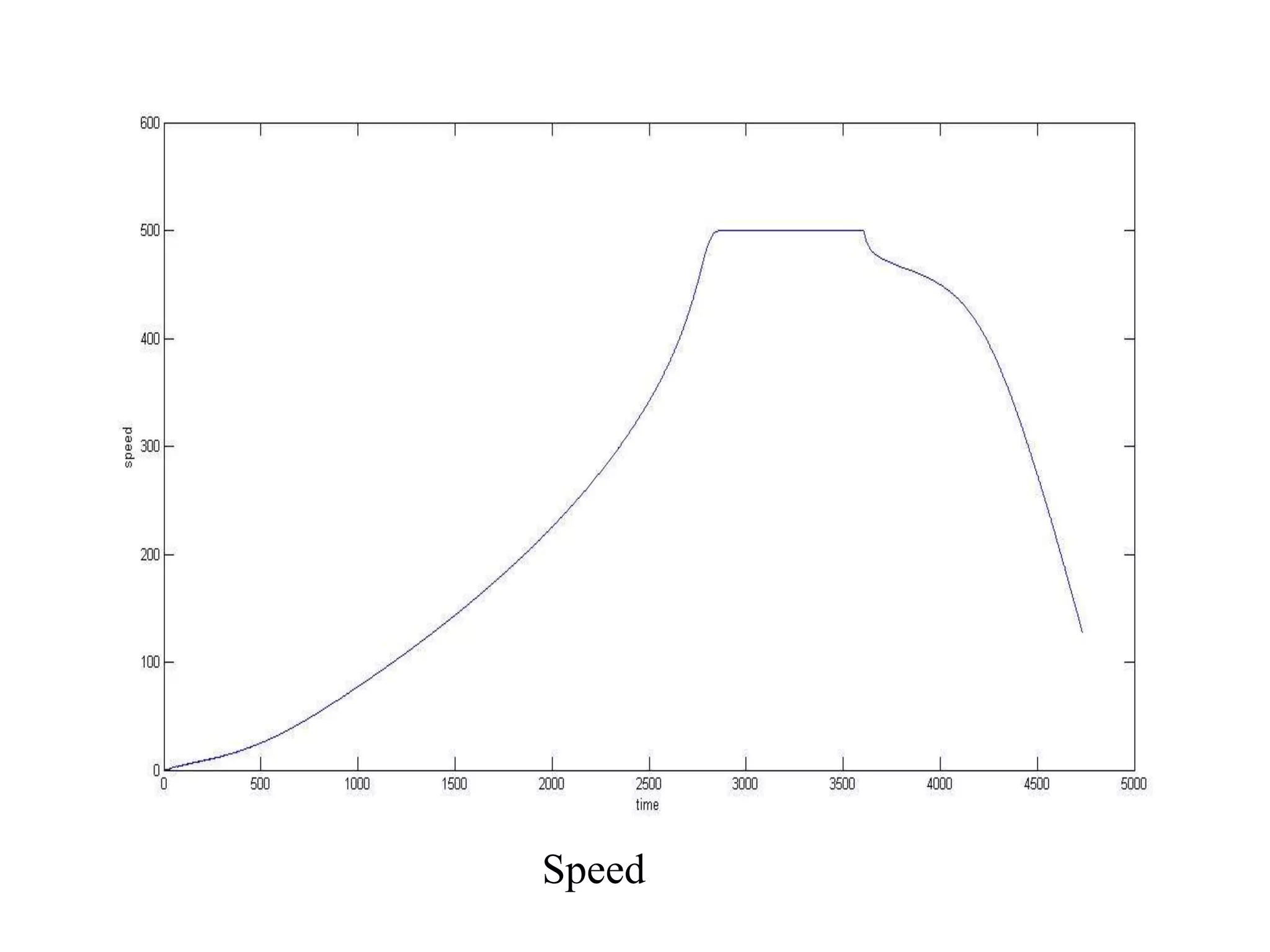
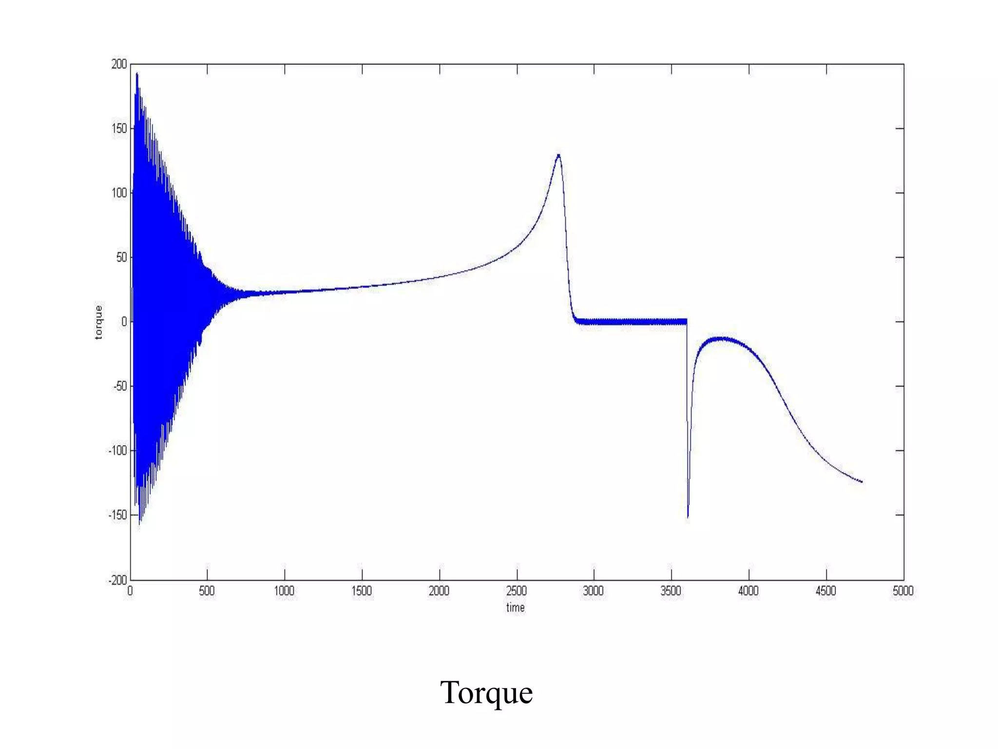
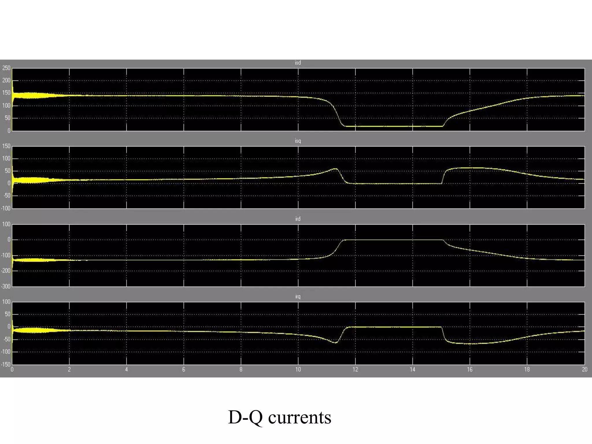
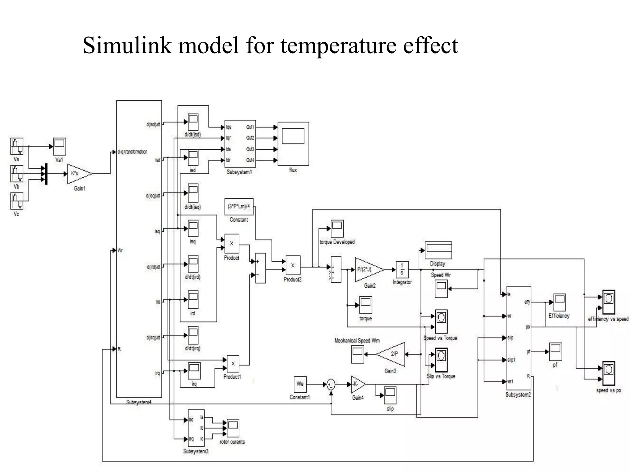
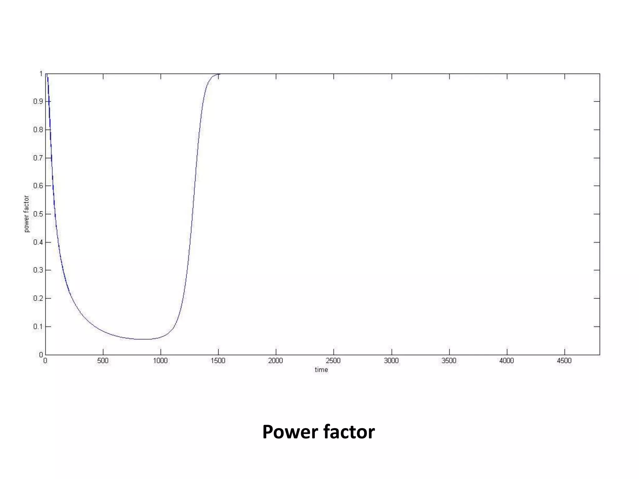
The document presents a project on induction motor modeling and applications, focusing on objectives, methodology, simulation results, and conclusions regarding the influence of temperature on motor parameters. Key findings include the development of equations for torque, rotor speed, and the impact of heating on efficiency and power factor, achieved through simulink modeling. Future work aims to enhance control algorithms for automatic speed adjustment and hardware implementation.