Downloaded 1,061 times
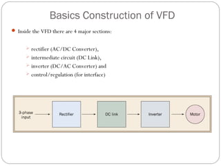
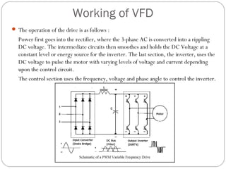


This document discusses variable frequency drives (VFDs) and their use in industrial settings. It describes the basic components and functioning of a VFD, including how they convert AC power to DC and then back to variable AC to control motor speed. VFDs allow motors to operate at optimal speeds, saving energy and reducing wear. The document outlines how to determine if a location would benefit from a VFD, such as if a pump valve is more than 30% closed. It provides examples of energy savings from installing VFDs on pumps. Key considerations for VFD installation include motor specifications, cable sizing, and programming start parameters. The major advantages of VFDs are energy savings, improved process control, lower maintenance needs


![A3918 low voltage dc motor driver allegro datasheet[1]](https://cdn.slidesharecdn.com/ss_thumbnails/a3918lowvoltagedcmotordriverallegro-datasheet1-121031142106-phpapp01-thumbnail.jpg?width=640&height=640&fit=bounds)