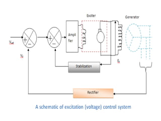
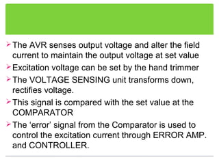
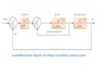
Automatic
Voltage Regulator
Presented by: Rajanikanta Tripathy
EEE-A
1201209207
Why do we need them?
 It is known that Voltage(V) of a power supply
system must be maintained at a constant value.
 Other wise the performance of any
motor/machinery will drop considerably.
 When any new load is given to an un-regulated
AC Generator, the V drop is more substantial
Close control of generator voltage is required to
prevent such dips in V.
This control is achieved by an Automatic Voltage
Regulator (AVR)
The real need of the AVR is to deal with the
voltage dip following the sudden connection of
extra load and to restore the rated Voltage without
undue overshooting and regeneration(i.e. volatge
hunting)
INTRODUCTION TO EXCITATION
SYSTEM
The basic function of an excitation system is to
provide necessary direct current to the field
winding of the synchronous generator.
The excitation system must be able to
automatically adjust the field current to maintain
the required terminal voltage.
The DC field current is obtained from a
separate source called an exciter.
Introduction To Exciter
It is necessary to provide constancy of the
alternator terminal voltage during normal small and
slow changes in the load.
 For this purpose the alternators are provided with
Automatic Voltage Regulator (AVR). The exciter is
the main component in the AVR loop.
It delivers DC power to the alternator field. It must
have adequate power capacity (in the low MW
range for large alternator) and sufficient speed of
response (rise time less than 0.1 sec.)
Main Components
• In older power plants, the exciter consisted of a DC
generator driven by the main shaft.
• This arrangement requires the transfer of DC power to
the synchronous generator field via slip rings and
brushes.
• Modern exciters tend to be of either brushless or
static design.
• In this arrangement, the exciter consists of an inverted
three phase alternator which has its three phase
armature on the rotor and its field on the stator.
The AVR senses output voltage and alter the field
current to maintain the output voltage at set value
Excitation voltage can be set by the hand trimmer
The VOLTAGE SENSING unit transforms down,
rectifies voltage.
This signal is compared with the set value at the
COMPARATOR
The ‘error’ signal from the Comparator is used to
control the excitation current through ERROR AMP.
and CONTROLLER.
Modelling of AVR
Three basic parts of AVR
Exciter Modelling
Synchronous generator Modelling
Excitor stabilization Modelling
Automatic voltaer regulator and it's modelling

Automatic voltaer regulator and it's modelling

  • 1.
    Automatic Voltage Regulator Presented by:Rajanikanta Tripathy EEE-A 1201209207
  • 2.
    Why do weneed them?  It is known that Voltage(V) of a power supply system must be maintained at a constant value.  Other wise the performance of any motor/machinery will drop considerably.  When any new load is given to an un-regulated AC Generator, the V drop is more substantial
  • 3.
    Close control ofgenerator voltage is required to prevent such dips in V. This control is achieved by an Automatic Voltage Regulator (AVR) The real need of the AVR is to deal with the voltage dip following the sudden connection of extra load and to restore the rated Voltage without undue overshooting and regeneration(i.e. volatge hunting)
  • 4.
    INTRODUCTION TO EXCITATION SYSTEM Thebasic function of an excitation system is to provide necessary direct current to the field winding of the synchronous generator. The excitation system must be able to automatically adjust the field current to maintain the required terminal voltage. The DC field current is obtained from a separate source called an exciter.
  • 6.
    Introduction To Exciter Itis necessary to provide constancy of the alternator terminal voltage during normal small and slow changes in the load.  For this purpose the alternators are provided with Automatic Voltage Regulator (AVR). The exciter is the main component in the AVR loop. It delivers DC power to the alternator field. It must have adequate power capacity (in the low MW range for large alternator) and sufficient speed of response (rise time less than 0.1 sec.)
  • 7.
    Main Components • Inolder power plants, the exciter consisted of a DC generator driven by the main shaft. • This arrangement requires the transfer of DC power to the synchronous generator field via slip rings and brushes. • Modern exciters tend to be of either brushless or static design. • In this arrangement, the exciter consists of an inverted three phase alternator which has its three phase armature on the rotor and its field on the stator.
  • 8.
    The AVR sensesoutput voltage and alter the field current to maintain the output voltage at set value Excitation voltage can be set by the hand trimmer The VOLTAGE SENSING unit transforms down, rectifies voltage. This signal is compared with the set value at the COMPARATOR The ‘error’ signal from the Comparator is used to control the excitation current through ERROR AMP. and CONTROLLER.
  • 9.
    Modelling of AVR Threebasic parts of AVR Exciter Modelling Synchronous generator Modelling Excitor stabilization Modelling