Downloaded 1,035 times
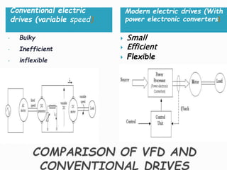
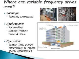
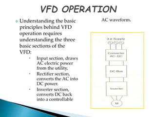
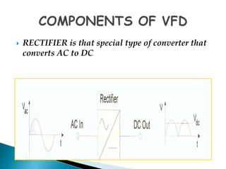
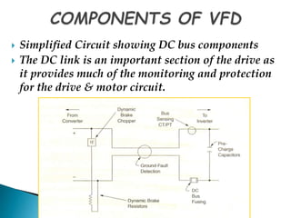
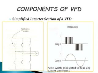
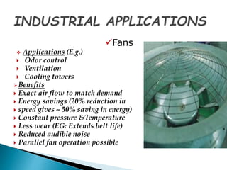
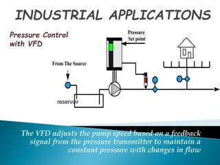
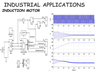


This document provides an overview of variable frequency drives (VFDs), including their components, operation, benefits, and applications. A VFD controls the frequency and voltage supplied to an electric motor, allowing it to run at variable speeds. It has three main sections - an input section that draws power, a rectifier that converts AC to DC, and an inverter that converts the DC back to a controlled AC waveform. VFDs provide benefits like energy savings, better process control, and protection for motors. Common industrial applications include fans, pumps, compressors, and chillers in HVAC systems.