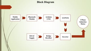
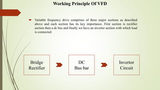
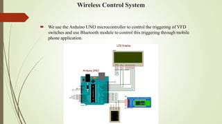
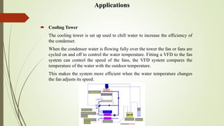
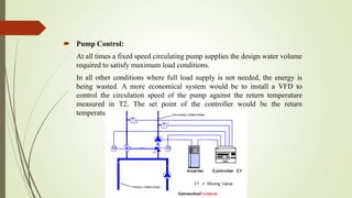
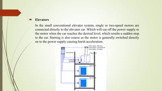
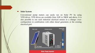
Gurgaon ✡️9711147426✨Call In girls Gurgaon Sector 51 escort service
Speed Control of 3Phase Induction Motor Using VFD(IOT Based)
1.
2. Speed Control of 3Phase Induction Motor Using VFD
(IOT Based)
Presented by:
Qammar Hussain
Hamza Majeed
Abdul Waheed
Advisor:
Mr. Imran Javed
3. Content
Introduction to VFD
Requirement of Speed Control
History of VFD
Components
Block Diagram
Working Principle of VFD
Circuit Diagram
Mobile Application
Wireless Control System
Application
Future Extension
Advantages
4. Introduction To VFD
A Variable Frequency Drive (VFD) is a type of motor controller that drives
an electric motor by varying the frequency and voltage supplied to the
electric motor. Other names for a VFD are variable speed drive, adjustable
speed drive, adjustable frequency drive, AC drive, Microdrive, and inverter.
Frequency (or hertz) is directly related to the motor’s speed (RPMs). In other
words, the faster the frequency, the faster the RPMs go. If an application
does not require an electric motor to run at full speed, the VFD can be used
to ramp down the frequency and voltage to meet the requirements of the
electric motor’s load
5. Requirement Of Speed Control
Speed Control Means Change The Drive Speed As Desired By The Process
To Maintain Different Process Parameter At Different Load .
Energy Saving.
Speed Control Is A Different Concept From Speed Regulation Where There
Is Natural Change In Speed Due Change In Load On The Shaft.
Speed Control Is Either Done Manually By The Operator Or By Means Of
Some Automatic Control Device.
Low Speed Starting Requirement.
6. History Of VFD
VFDs are used in applications ranging from small appliances to large
compressors. About 25% of the world's electrical energy is consumed by
electric motors in industrial applications. Systems using VFDs can be more
efficient than those using throttling control of fluid flow, such as in systems
with pumps and damper control for fans. However, the global market
penetration for all applications of VFDs is relatively small.
Over the last four decades, power electronics technology has reduced VFD
cost and size and has improved performance through advances in
semiconductor switching devices, drive topologies, simulation and control
techniques, and control hardware and software.
Variable frequency drive is typically a tool of power electronics without
having a great understanding of power electronics we can never get the
depth of variable frequency drive.
7. Components
220 AC Supply
Bridge Rectifier
Filter Circuit
MOSFET
3 Phase Motor
Arduino UNO
Bluetooth Module
Mobile Applications
Jumper Wires
9. Working Principle Of VFD
Variable frequency drive comprises of three major sections as described
above and each section has its key importance. First section is rectifier
section then a dc bus and finally we have an inverter section with which load
is connected.
Bridge
Rectifier
DC
Bus bar
Invertor
Circuit
10. Bridge Rectifier
This section can comprises of diodes, transistors or silicon controlled
rectifiers. But usually diodes are used because of their lower cost. AC
voltages coming from main line have positive and negative peaks. When
these voltages are fed in to bridge type configuration of diodes of this
rectifier section the negative peaks are vanished only positive peaks retain.
In this way the frequency of the coming voltages doubles. This rectifier
section also called AC to DC converter.
11. DC Bus
DC bus is used to store voltages coming from AC to DC converter.
This consist of capacitors and some other items like inductors or chokes in
order to smooth the power supply coming from the previous section.
Thus ripples are further removed by storing voltages in this DC bus.
Thus this DC bus can be of great use not only for removing ripples but also
helps in improving power factor correction
12. Microcontroller Based PWM
Pulse width modulation is the basic technique used very widely for
controlling motor speed and frequency. This can be done by using
microcontroller. In this research we selected a range of 5Hz to 50Hz
frequency using PWM. The basic principle of PWM is a sine wave is
generated in the microcontroller which is super imposed on a triangular
wave. This results in a square wave which is then fed to inverter section. The
width of this square wave can be controlled by changing the duty cycles of
the pulse. Basically duty cycles describes the time for which pulse waveform
turned on and off thus by switching the waveform between two discrete
levels the square wave is approximated with a sine wave of desired duty
cycles.
14. Mobile Application
VFD control mobile application We can
change the speed of three phase induction
motor through this mobile application.
VFD control application connect to
hardware through Bluetooth module
(HC-05).
When we change the speed parameter in
mobile so we can see physical results on
hardware.
15. Wireless Control System
We use the Arduino UNO microcontroller to control the triggering of VFD
switches and use Bluetooth module to control this triggering through mobile
phone application.
16. Applications
Cooling Tower
The cooling tower is set up used to chill water to increase the efficiency of
the condenser.
When the condenser water is flowing fully over the tower the fan or fans are
cycled on and off to control the water temperature. Fitting a VFD to the fan
system can control the speed of the fans, the VFD system compares the
temperature of the water with the outdoor temperature.
This makes the system more efficient when the water temperature changes
the fan adjusts its speed.
17. Constant Air Volume (CAV) System:
A constant air volume supplies a constant air to a typical space to control the
temperature in the space.
The system design provides sufficient capacity to deliver supply air to the
space for design load conditions. If the VFD is fitted to the air blowing
system the air flow will be controlled with VFD by controlling the speed of
blowers the load condition. The motor will only run at full speed when full
heating or full cooling is related to called for.
18. Pump Control:
At all times a fixed speed circulating pump supplies the design water volume
required to satisfy maximum load conditions.
In all other conditions where full load supply is not needed, the energy is
being wasted. A more economical system would be to install a VFD to
control the circulation speed of the pump against the return temperature
measured in T2. The set point of the controller would be the return
temperature (design at full load)
19. Elevators
In the small conventional elevator system, single or two-speed motors are
connected directly to the elevator car. Which will cut off the power supply to
the motor when the car reaches the desired level, which results a sudden stop
to the car. Starting is also coarse as the motor is generally switched directly
on to the power supply causing harsh acceleration.
20. Solar System
Conventional pump motors can easily run on Solar PV by using
VFD drives. VFD drives are available from 1kW to 50kW and above. It is
also possible to run such industrial electrical motors in a change- over-
configuration in combination with either diesel generators or the existing
electrical grid.
21. Future Extension
Collect the solar system data on mobile phone through web.
In industries when temperature is increased so fan speed will be increase.
Also used in poultry farm to control fan speed.
Remote access of system through mobile.
22. Advantages
Reduction in maintenance costs.
Variable speed drives are inherently soft start, increasing motor and linkage
life.
Start-Stop and reset of pumps can be done by the variable speed drives.
In applications, where increased flow is required, on a temporary basis, the
lead or primary pump may remain at maximum flow with the second back
pump enabled and varied to meet the system demand.