This document provides information about RF and microwave engineering:
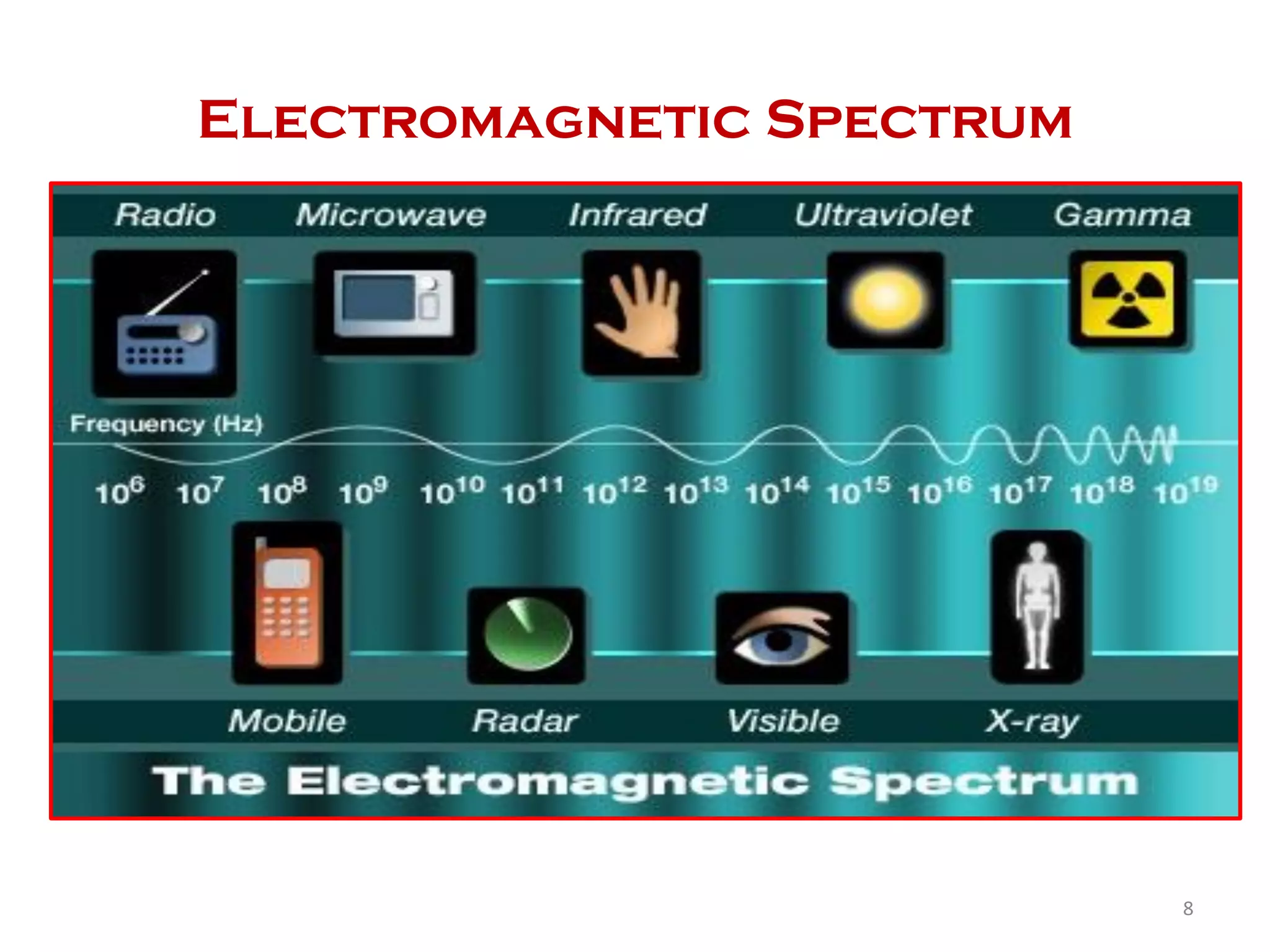
1. It defines radio frequency as any electromagnetic wave frequency between 3KHz to 300GHz, which includes frequencies used for communications and radar signals. Microwaves are defined as electromagnetic waves between 300MHz to 300GHz.
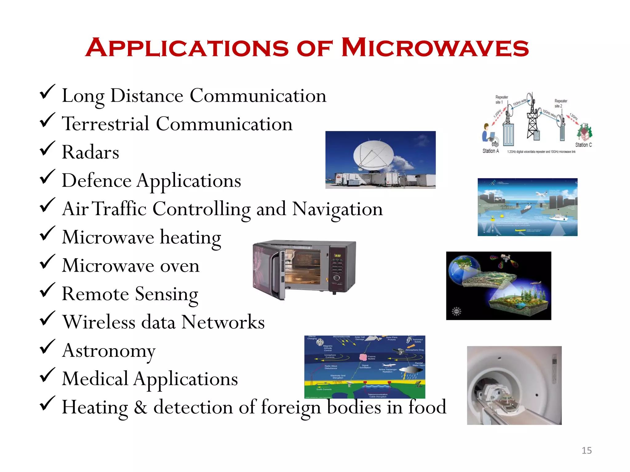
2. Microwave engineering deals with the design of communication, navigation, and other systems that operate in the microwave frequency range. Key applications discussed include microwave ovens, radar, satellite communication, and TV.
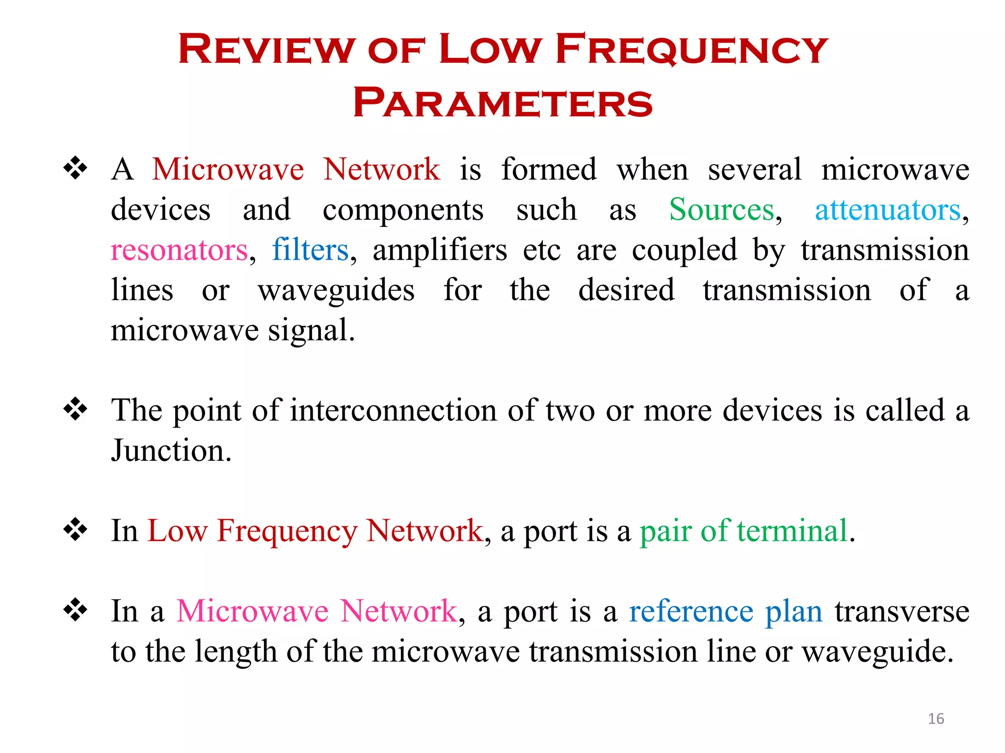
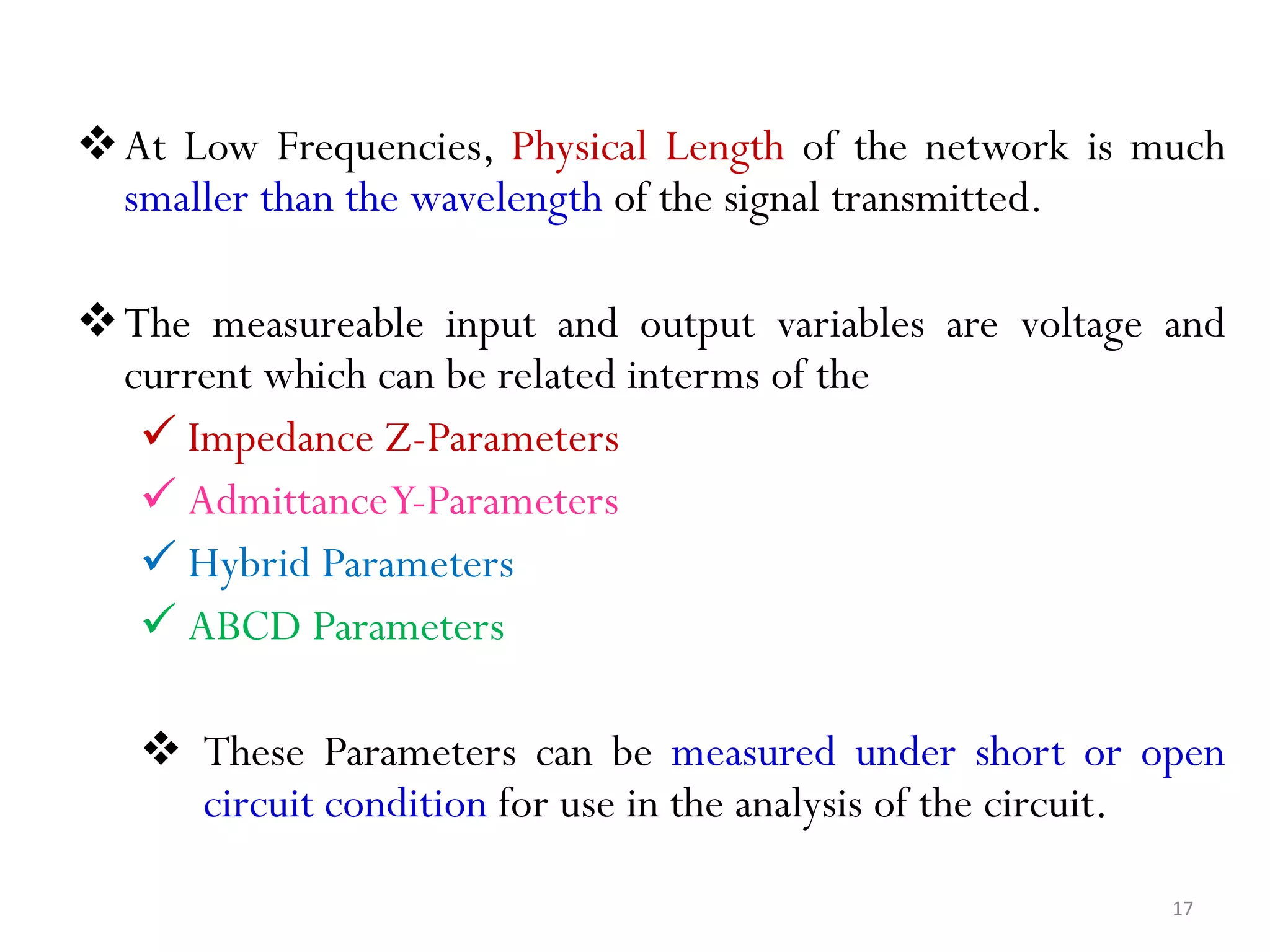
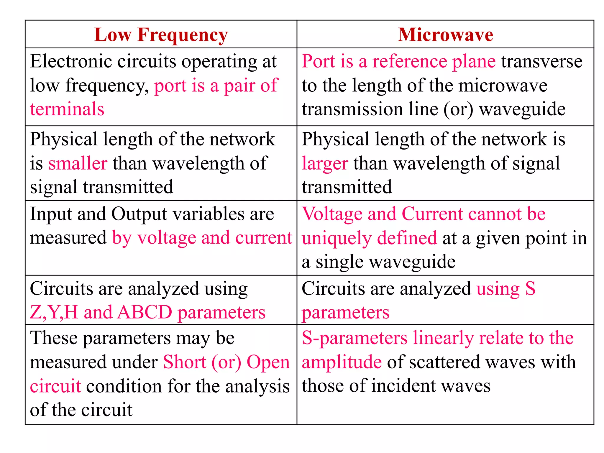
3. Analysis of microwave circuits differs from low frequency circuits as the physical length of components is larger than signal wavelengths. S-parameters are used to relate the amplitude of scattered waves to incident waves in microwave circuit analysis.


![Properties of S-Matrix
• S-matrix [S] is always a square matrix of order (n x n) and its
elements are complex quantities (real and imaginary part)
• [S] is a symmetric matrix (i.e) Sij=Sji
• [S] is a unitary matrix (i.e) [S][S]* = [I]
Where [S]* - Complex Conjugate of [S]
[I] - Unit Matrix (or) Identity matrix of same order as
that of [S]
• Under perfect matched conditions; the diagonal elements of [S]
are zero
• The sum of product of each term of any row (or) column
multiplied by the complex conjugate of the corresponding terms
of any other row ((or) column) is zero
jkforSS ij
n
i
ik
0*
1](https://image.slidesharecdn.com/rfandmicrowaveengineering-190807051107/75/RF-and-Microwave-Engineering-41-2048.jpg)