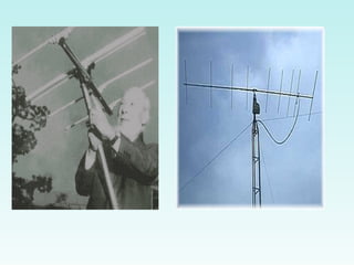
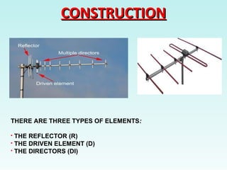
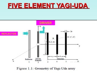
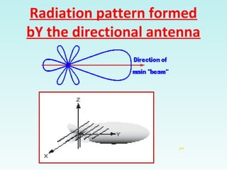
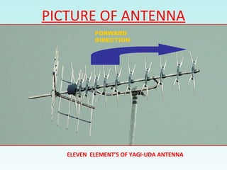
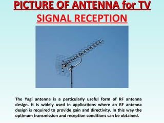
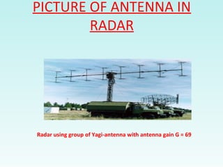
Presented by
Ms.R.Krishnaveni
Assistant Professor
Department of ECE
KIT-Kalaignarkarunanidhi Institute of Technology
CONTENTCONTENT
 INDRODUCTIONINDRODUCTION
 PRINCIPLEPRINCIPLE
 CONSTRUCTIONCONSTRUCTION
 WORKING.WORKING.
 PICTURE OF ANTENNA.PICTURE OF ANTENNA.
 ADVANTAGESADVANTAGES
 DISADVANTAGES.DISADVANTAGES.
 INTRODUCTION.INTRODUCTION.
 APPLICATIONS.APPLICATIONS.
INTRODUCTIONINTRODUCTION
The Yagi-Uda antenna or Yagi Antenna is one of the most brilliant
antenna designs. It is simple to construct and has a high gain
typically greater than 10 dB.
The Yagi-Uda antennas typically operate in the HF to UHF bands
(about 3 MHz to 3 GHz) and Covers 40 to 60 Km.
A Directional Antenna System Consisting of an array of Coupled
Parallel Dipoles. This is commonly known as Yagi-uda or Simply Yagi
Antenna.
Yagi-uda Antenna is familiar as the Commonest kind Of
Terrestrial TV Antenna to be found on the Roof tops of houses.
PRINCIPLEPRINCIPLE
 Yagi-uda antenna is an electromagnetic device that collects radio
waves.
 An antenna tuned to a particular frequency will resonate to a radio
signal of the same frequency
CONSTRUCTIONCONSTRUCTION
THERE ARE THREE TYPES OF ELEMENTS:
 THE REFLECTOR (R)
 THE DRIVEN ELEMENT (D)
 THE DIRECTORS (DI)
CONSTRUCTIONCONSTRUCTION
DRIVEN ELEMENT :
The driven element of a Yagi is the feed point where the feed line is
attached from the transmitter to the Yagi to perform the transfer of
power from the transmitter to the antenna.
A dipole driven element will be "resonant" when its electrical
length is 1/2 of the wavelength of the frequency applied to its feed
point.
The feed point in the picture above is on the center of the driven
element.
CONSTRUCTIONCONSTRUCTION
DIRECTOR :
The director is the shortest of the parasitic elements and this end of
the Yagi is aimed at the receiving station. It is resonant slightly higher
in frequency than the driven element, and its length will be about 5%
shorter, progressively than the driven element.
The directors lengths can vary, depending upon the director spacing,
the number of directors used in the antenna, the desired pattern,
pattern bandwidth and element diameter.
The amount of gain is directly proportional to the length of the
antenna array and not by the number of directors used.
CONSTRUCTIONCONSTRUCTION
REFLECTOR
The reflector is the element that is placed at the rear of the driven
element (The dipole).
It's resonant frequency is lower, and its length is approximately 5%
longer than the driven element. It's length will vary depending on the
spacing and the element diameter
The spacing of the reflector will be between .1 wavelength and .25
wavelength. It's spacing will depend upon the gain, bandwidth, F/B
ratio, and side lobe pattern requirements of the final antenna design.
WorkingWorking
 Reflector here derives it’s main Power from a driver , it reduces the
signal strength in it’s own direction and thus reflectes the radiation
towardes the driver and directors.
 The driven element is where the signal is intercpeted by the
receiving equipment and has the cable attached that takes the
recevied signal to the receiver
 The radiator and driver can be placed more closer to increase the
radiation length towards the directors.
WAVELENGTH = 3*10^8WAVELENGTH = 3*10^8
FERQUENCY(MHz)FERQUENCY(MHz)
 To Determine The Wave-length Of A Radio Station With A
Frequency Of 92.1 Mhz , SIMPLY DIVIDE THE SPEED OF LIGHT
( 300,000,000 METERS PER SECOND) BY 92,100,000 CYCLES
PER SECOND.
 The Seconds Cancels Out In The Formula With The Wave-
length Ending Up At 3.26 Meters. In Other Words The Waves
Passing You Buy Right Now From A Radio Station Transmitting
At 92.1 Mhz ARE 3.26 Meters Long.
FIVE ELEMENT YAGI-UDAFIVE ELEMENT YAGI-UDA
REFLECTOR
DRIVER
Radiation pattern formed
bY the directional antenna
jack
Radiation pattern formed
bY the directional antenna
jack
 The antenna exhibits a directional pattern consisting of a
main forward lobe and a number of spurious side lobes.
 The main one of these is the reverse lobe caused by
radiation in the direction of the reflector.
 The antenna can be optimised to either reduce this or
produce the maximum level of forward gain.
PICTURE OF ANTENNA
ELEVEN ELEMENT’S OF YAGI-UDA ANTENNA
FORWARD
DIRECTION
PICTURE OF ANTENNA for TVPICTURE OF ANTENNA for TV
SIGNAL RECEPTION
The Yagi antenna is a particularly useful form of RF antenna
design. It is widely used in applications where an RF antenna
design is required to provide gain and directivity. In this way the
optimum transmission and reception conditions can be obtained.
PICTURE OF ANTENNA IN
RADAR
Radar using group of Yagi-antenna with antenna gain G = 69
ADVANTAGES
 It has a Moderate Gain Of About 7 (dB).
 It is a Directional Antenna.
 Can be used at High Frequency.
 Adjustable from to Back Ratio.
DISADVANTAGES
 The Gain is not Very High.
 Needs a large number of Elements to be used.
APPLICATIONS
 Yagi-uda antenna is a unidirectional antenna. Used for
television recivers.They provide better tunning because
of large bandwidth and has decent gain.
YAGI UDA Antenna

YAGI UDA Antenna

  • 1.
    Presented by Ms.R.Krishnaveni Assistant Professor Departmentof ECE KIT-Kalaignarkarunanidhi Institute of Technology
  • 2.
    CONTENTCONTENT  INDRODUCTIONINDRODUCTION  PRINCIPLEPRINCIPLE CONSTRUCTIONCONSTRUCTION  WORKING.WORKING.  PICTURE OF ANTENNA.PICTURE OF ANTENNA.  ADVANTAGESADVANTAGES  DISADVANTAGES.DISADVANTAGES.  INTRODUCTION.INTRODUCTION.  APPLICATIONS.APPLICATIONS.
  • 3.
    INTRODUCTIONINTRODUCTION The Yagi-Uda antennaor Yagi Antenna is one of the most brilliant antenna designs. It is simple to construct and has a high gain typically greater than 10 dB. The Yagi-Uda antennas typically operate in the HF to UHF bands (about 3 MHz to 3 GHz) and Covers 40 to 60 Km. A Directional Antenna System Consisting of an array of Coupled Parallel Dipoles. This is commonly known as Yagi-uda or Simply Yagi Antenna. Yagi-uda Antenna is familiar as the Commonest kind Of Terrestrial TV Antenna to be found on the Roof tops of houses.
  • 5.
    PRINCIPLEPRINCIPLE  Yagi-uda antennais an electromagnetic device that collects radio waves.  An antenna tuned to a particular frequency will resonate to a radio signal of the same frequency
  • 6.
    CONSTRUCTIONCONSTRUCTION THERE ARE THREETYPES OF ELEMENTS:  THE REFLECTOR (R)  THE DRIVEN ELEMENT (D)  THE DIRECTORS (DI)
  • 7.
    CONSTRUCTIONCONSTRUCTION DRIVEN ELEMENT : Thedriven element of a Yagi is the feed point where the feed line is attached from the transmitter to the Yagi to perform the transfer of power from the transmitter to the antenna. A dipole driven element will be "resonant" when its electrical length is 1/2 of the wavelength of the frequency applied to its feed point. The feed point in the picture above is on the center of the driven element.
  • 8.
    CONSTRUCTIONCONSTRUCTION DIRECTOR : The directoris the shortest of the parasitic elements and this end of the Yagi is aimed at the receiving station. It is resonant slightly higher in frequency than the driven element, and its length will be about 5% shorter, progressively than the driven element. The directors lengths can vary, depending upon the director spacing, the number of directors used in the antenna, the desired pattern, pattern bandwidth and element diameter. The amount of gain is directly proportional to the length of the antenna array and not by the number of directors used.
  • 9.
    CONSTRUCTIONCONSTRUCTION REFLECTOR The reflector isthe element that is placed at the rear of the driven element (The dipole). It's resonant frequency is lower, and its length is approximately 5% longer than the driven element. It's length will vary depending on the spacing and the element diameter The spacing of the reflector will be between .1 wavelength and .25 wavelength. It's spacing will depend upon the gain, bandwidth, F/B ratio, and side lobe pattern requirements of the final antenna design.
  • 10.
    WorkingWorking  Reflector herederives it’s main Power from a driver , it reduces the signal strength in it’s own direction and thus reflectes the radiation towardes the driver and directors.  The driven element is where the signal is intercpeted by the receiving equipment and has the cable attached that takes the recevied signal to the receiver  The radiator and driver can be placed more closer to increase the radiation length towards the directors.
  • 11.
    WAVELENGTH = 3*10^8WAVELENGTH= 3*10^8 FERQUENCY(MHz)FERQUENCY(MHz)  To Determine The Wave-length Of A Radio Station With A Frequency Of 92.1 Mhz , SIMPLY DIVIDE THE SPEED OF LIGHT ( 300,000,000 METERS PER SECOND) BY 92,100,000 CYCLES PER SECOND.  The Seconds Cancels Out In The Formula With The Wave- length Ending Up At 3.26 Meters. In Other Words The Waves Passing You Buy Right Now From A Radio Station Transmitting At 92.1 Mhz ARE 3.26 Meters Long.
  • 12.
    FIVE ELEMENT YAGI-UDAFIVEELEMENT YAGI-UDA REFLECTOR DRIVER
  • 13.
    Radiation pattern formed bYthe directional antenna jack
  • 14.
    Radiation pattern formed bYthe directional antenna jack  The antenna exhibits a directional pattern consisting of a main forward lobe and a number of spurious side lobes.  The main one of these is the reverse lobe caused by radiation in the direction of the reflector.  The antenna can be optimised to either reduce this or produce the maximum level of forward gain.
  • 15.
    PICTURE OF ANTENNA ELEVENELEMENT’S OF YAGI-UDA ANTENNA FORWARD DIRECTION
  • 16.
    PICTURE OF ANTENNAfor TVPICTURE OF ANTENNA for TV SIGNAL RECEPTION The Yagi antenna is a particularly useful form of RF antenna design. It is widely used in applications where an RF antenna design is required to provide gain and directivity. In this way the optimum transmission and reception conditions can be obtained.
  • 17.
    PICTURE OF ANTENNAIN RADAR Radar using group of Yagi-antenna with antenna gain G = 69
  • 18.
    ADVANTAGES  It hasa Moderate Gain Of About 7 (dB).  It is a Directional Antenna.  Can be used at High Frequency.  Adjustable from to Back Ratio.
  • 19.
    DISADVANTAGES  The Gainis not Very High.  Needs a large number of Elements to be used.
  • 20.
    APPLICATIONS  Yagi-uda antennais a unidirectional antenna. Used for television recivers.They provide better tunning because of large bandwidth and has decent gain.