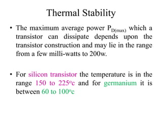
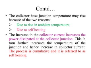
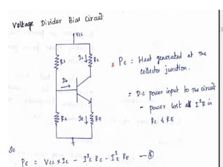
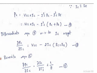
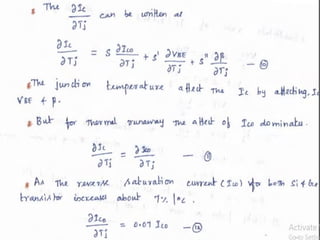
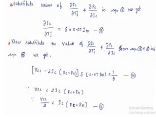
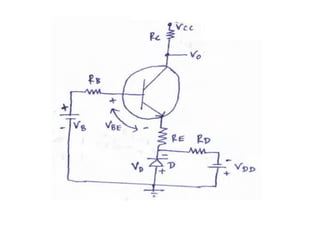
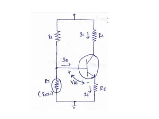
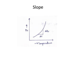
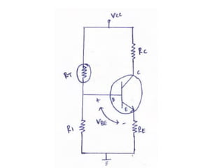
Thermal Stability and Bias
Compensation
Mrs.V.SrirengaNachiyar
Ramco Institute of Technology
Thermal Stability
• The maximum average power PD(max) which a
transistor can dissipate depends upon the
transistor construction and may lie in the range
from a few milli-watts to 200w.
• For silicon transistor the temperature is in the
range 150 to 225oc and for germanium it is
between 60 to 100oc
Contd…
• The collector base junction temperature may rise
because of the two reasons:
 Due to rise in ambient temperature
 Due to self heating
• The increase in the collector current increases the
power dissipated at the collector junction. This in
turn further increases the temperature of the
junction and hence increase in collector current.
The process is cumulative and it is referred to as
self heating
Contd…
• The excess heat produced at the collector base
junction may even burn and destroy the
transistor. This situation is called “Thermal
Runaway”.
Thermal resistance
• The steady state temperature rise at the collector
junction is proportional to the power dissipated at the
junction. It is given as,
δT = θ.PD =Tj- TA
Where Tj – junction temperature in oC
TA – Ambient temperature in oC
PD – Power in watts dissipated at the collector
junction
θ – constant of proportionality
Contd…
• The θ, which is constant of proportionality is
referred to as thermal resistance.
θ=
𝑇 𝑗−𝑇 𝐴
𝑃 𝐷
• The unit of θ is oC/W
• The typical value of θ for a various transistor
vary from 0.2oC/W for a high power transistor
with an efficient heat sink to 1000oC/W for a low
power transistor
• The maximum collector power PC allowed for
safe operation is specified at 25oC
The condition for thermal stability
• The thermal runaway may even burn and
destroy the transistor, it is necessary to avoid
thermal runaway.
• The required condition to avoid thermal
runaway is that the rate at which heat is
released at the collector junction must not
exceed the rate at which the heat can be
dissipated.
• It is given by,
Contd…
• This condition must be satisfied to prevent
thermal runaway.
• By proper design of biasing circuit, it is
possible to ensure that the transistor cannot
runaway below a specific amount of ambient
temperature.
Compensation techniques
Temperature sensitive devices such as diodes,
transistors are used which provide compensating
voltages and currents to maintain the operating
point constant.
1. Diode compensation for instability due to VBE.
2. Diode compensation for instability due to ICO.
3. Thermistor compensation.
4. Sensistor compensation.
Diode compensation for instability due
to VBE.
• For germanium transistor, changes in ICO with
temperature contributes more problem than for
silicon transistor.
• On the other hand, in a silicon transistor, the
changes of VBE with temperature posses
significantly to the changes in IC.
• Thus a diode may be used as compensation
element for variation in VBE or ICO.
Cont…
• In this case, the diode is kept forward biased
by the diode source VDD & Rd.
• Apply KVL to the base circuit.
Diode compensation for instability due
to ICO
• The diode D and the transistor are of same
type and same material.
• So the reverse saturation current ICO and diode
will increase with temperature at same rate as
the transistor collector saturation current ICO
Cont…
• The diode is reverse biased by VBE, W.K.T in
case of germanium transistor VBE is 0.3V. So
the current through Diode is reverse saturation
current:
• IB = I-IO
IC = β IB + (1+β)ICO
Thermistor compensation
• Consider self-bias circuit with thermistor RT as
a compensating element.
• The thermistor has a negative temperature
coefficient and its resistance decreases
exponentially with increasing temperature.
• Slope of the curve = ∂RT/ ∂T. This is the
temperature coefficient for thermistor and the
slope is negative.
Cont…
• With increase in temperature, RT decreases.
Hence voltage drop across it also decreases.
• The voltage drop is nothing but the voltage at
the base with respect to ground. Hence VBE
decreases which reduces IB.
Sensistor Compensation.
• This method uses temperature sensitive
resistive element rather than diodes or
transistors. It has a positive temperature
coefficient.
• Its resistance increases exponentially with
increasing temperature .
• Slope of this curve= ∂RT/ ∂T.
• Slope is positive.
Slope
Cont…
• Resistor R1 can be replaced by sensistor
element RT in self- bias circuit.
• As temperature increases, RT increases which
decrease the current flowing through it. Hence
current through R2 decreases which reduces
the voltage drop across it.
• The voltage drop R2 is the voltage at the base
with respect to ground. Hence VBE decreases
which reduces IB.
References
1. Donald. A. Neamen, Electronic Circuits
Analysis and Design, 3rd Edition, Mc Graw
Hill Education (India) Private Ltd., 2010.
2. Robert L. Boylestad and Louis Nasheresky,
―Electronic Devices and Circuit Theory, 11th
Edition, Pearson Education, 2013.
3. A.P.Godse & U.A. Bakshi,”Electronic
Circuits-I”
4. S.Salivahanan & N.Sureshkumar,”Electronic
Circuits-I”

Thermal stability & bias compensation

  • 1.
    Thermal Stability andBias Compensation Mrs.V.SrirengaNachiyar Ramco Institute of Technology
  • 2.
    Thermal Stability • Themaximum average power PD(max) which a transistor can dissipate depends upon the transistor construction and may lie in the range from a few milli-watts to 200w. • For silicon transistor the temperature is in the range 150 to 225oc and for germanium it is between 60 to 100oc
  • 3.
    Contd… • The collectorbase junction temperature may rise because of the two reasons:  Due to rise in ambient temperature  Due to self heating • The increase in the collector current increases the power dissipated at the collector junction. This in turn further increases the temperature of the junction and hence increase in collector current. The process is cumulative and it is referred to as self heating
  • 4.
    Contd… • The excessheat produced at the collector base junction may even burn and destroy the transistor. This situation is called “Thermal Runaway”.
  • 5.
    Thermal resistance • Thesteady state temperature rise at the collector junction is proportional to the power dissipated at the junction. It is given as, δT = θ.PD =Tj- TA Where Tj – junction temperature in oC TA – Ambient temperature in oC PD – Power in watts dissipated at the collector junction θ – constant of proportionality
  • 6.
    Contd… • The θ,which is constant of proportionality is referred to as thermal resistance. θ= 𝑇 𝑗−𝑇 𝐴 𝑃 𝐷 • The unit of θ is oC/W • The typical value of θ for a various transistor vary from 0.2oC/W for a high power transistor with an efficient heat sink to 1000oC/W for a low power transistor • The maximum collector power PC allowed for safe operation is specified at 25oC
  • 7.
    The condition forthermal stability • The thermal runaway may even burn and destroy the transistor, it is necessary to avoid thermal runaway. • The required condition to avoid thermal runaway is that the rate at which heat is released at the collector junction must not exceed the rate at which the heat can be dissipated. • It is given by,
  • 9.
    Contd… • This conditionmust be satisfied to prevent thermal runaway. • By proper design of biasing circuit, it is possible to ensure that the transistor cannot runaway below a specific amount of ambient temperature.
  • 14.
    Compensation techniques Temperature sensitivedevices such as diodes, transistors are used which provide compensating voltages and currents to maintain the operating point constant. 1. Diode compensation for instability due to VBE. 2. Diode compensation for instability due to ICO. 3. Thermistor compensation. 4. Sensistor compensation.
  • 15.
    Diode compensation forinstability due to VBE. • For germanium transistor, changes in ICO with temperature contributes more problem than for silicon transistor. • On the other hand, in a silicon transistor, the changes of VBE with temperature posses significantly to the changes in IC. • Thus a diode may be used as compensation element for variation in VBE or ICO.
  • 17.
    Cont… • In thiscase, the diode is kept forward biased by the diode source VDD & Rd. • Apply KVL to the base circuit.
  • 18.
    Diode compensation forinstability due to ICO • The diode D and the transistor are of same type and same material. • So the reverse saturation current ICO and diode will increase with temperature at same rate as the transistor collector saturation current ICO
  • 19.
    Cont… • The diodeis reverse biased by VBE, W.K.T in case of germanium transistor VBE is 0.3V. So the current through Diode is reverse saturation current: • IB = I-IO IC = β IB + (1+β)ICO
  • 20.
    Thermistor compensation • Considerself-bias circuit with thermistor RT as a compensating element. • The thermistor has a negative temperature coefficient and its resistance decreases exponentially with increasing temperature. • Slope of the curve = ∂RT/ ∂T. This is the temperature coefficient for thermistor and the slope is negative.
  • 23.
    Cont… • With increasein temperature, RT decreases. Hence voltage drop across it also decreases. • The voltage drop is nothing but the voltage at the base with respect to ground. Hence VBE decreases which reduces IB.
  • 24.
    Sensistor Compensation. • Thismethod uses temperature sensitive resistive element rather than diodes or transistors. It has a positive temperature coefficient. • Its resistance increases exponentially with increasing temperature . • Slope of this curve= ∂RT/ ∂T. • Slope is positive.
  • 25.
  • 26.
    Cont… • Resistor R1can be replaced by sensistor element RT in self- bias circuit. • As temperature increases, RT increases which decrease the current flowing through it. Hence current through R2 decreases which reduces the voltage drop across it. • The voltage drop R2 is the voltage at the base with respect to ground. Hence VBE decreases which reduces IB.
  • 28.
    References 1. Donald. A.Neamen, Electronic Circuits Analysis and Design, 3rd Edition, Mc Graw Hill Education (India) Private Ltd., 2010. 2. Robert L. Boylestad and Louis Nasheresky, ―Electronic Devices and Circuit Theory, 11th Edition, Pearson Education, 2013. 3. A.P.Godse & U.A. Bakshi,”Electronic Circuits-I” 4. S.Salivahanan & N.Sureshkumar,”Electronic Circuits-I”