Downloaded 260 times
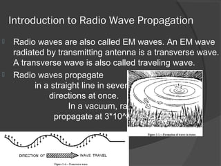
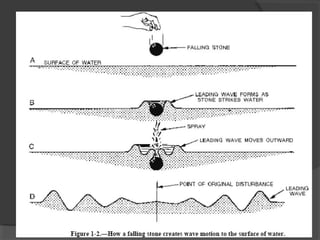
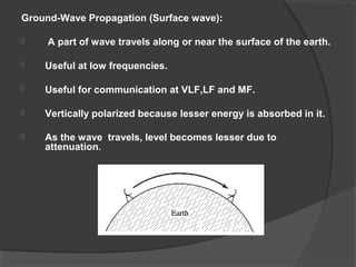
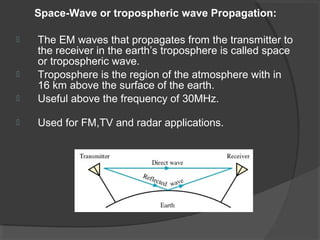
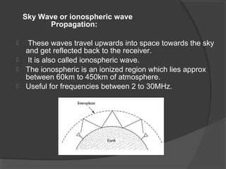


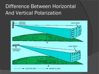
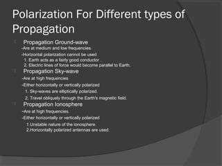


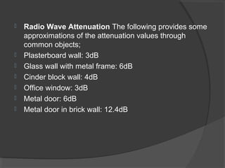


The document discusses various topics related to radio wave propagation. It covers the different types of propagation including ground wave, space wave, and sky wave. It describes line of sight propagation and how increasing antenna height allows communication over longer distances. Tropospheric propagation is discussed along with how turbulence in the troposphere can scatter radio waves. The document also covers polarization of radio waves for different propagation types and the advantages of horizontal and vertical polarization. Finally, it defines attenuation and provides examples of attenuation levels through common materials.


