Downloaded 794 times
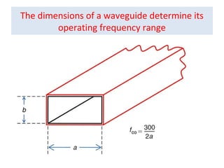
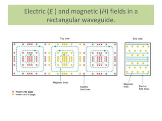
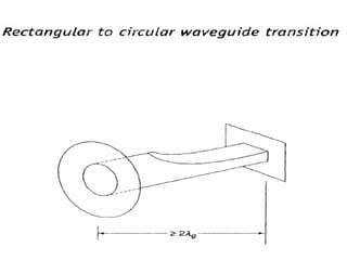
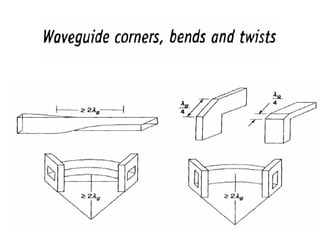
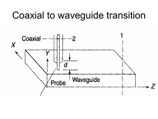
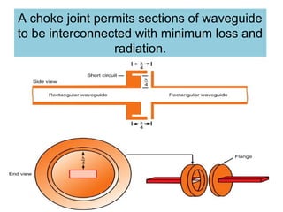
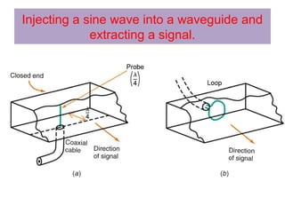
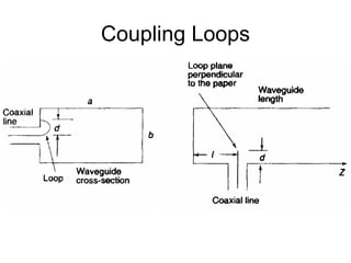
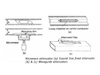
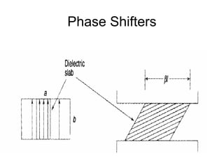
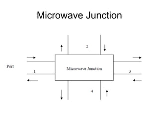
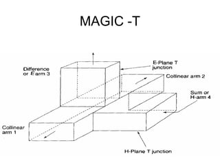
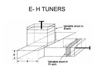
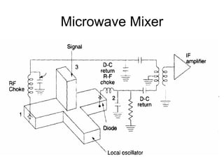
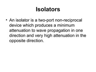
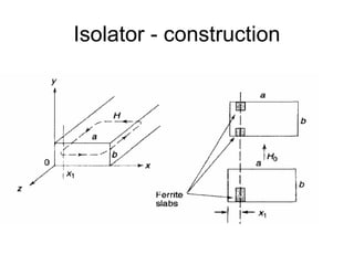
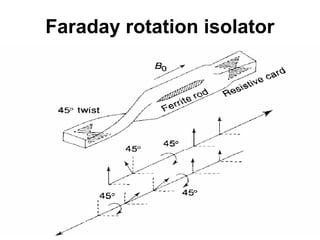
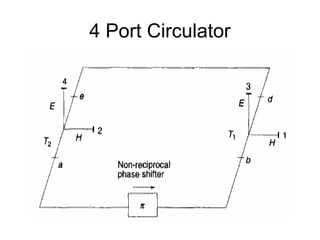
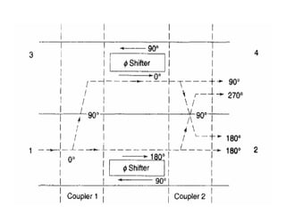
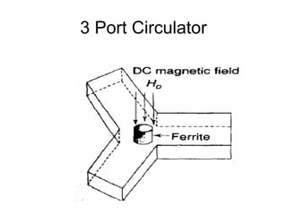
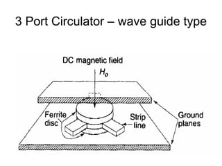
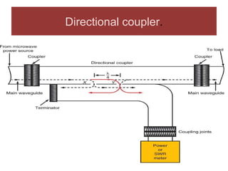
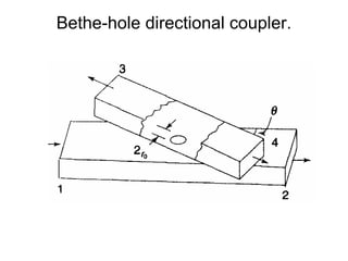
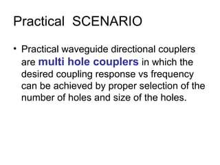
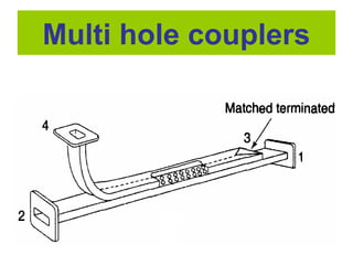


The document summarizes key components and concepts in basic microwave engineering. It discusses waveguides and their operating frequencies based on dimensions. It also describes electric and magnetic fields in rectangular waveguides. Additional components summarized include coaxial to waveguide transitions, choke joints, coupling loops, phase shifters, junctions, tuners, mixers, isolators, circulators, directional couplers, and cavity resonators. Isolators, circulators, and directional couplers are multi-port devices that control the direction of signal propagation with differing levels of attenuation.


