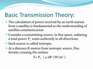
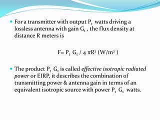
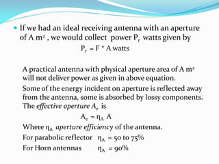
This document provides an overview of satellite communication link design. It discusses basic transmission theory including the link equation and factors that affect received power such as EIRP, path loss, and antenna gains. It also covers system noise temperature and the G/T ratio. The document outlines considerations for designing downlinks and uplinks. It describes how to calculate overall C/N ratio when multiple C/N ratios are present in the link. Finally, it lists the typical steps involved in designing a satellite communication link for a specified C/N requirement.
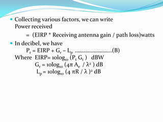
Satellite Link Design:
EIRP, Transmission Losses, Free-space transmission, System noise temperature and G/T ratio, Noise figure, Design of downlinks, Design of uplink, Design of specified C/N: combining C/N and C/I values in satellite links, Overall C/No, Link design procedure.
The attached narrated power point presentation attempts to explain the methods of computation of total power loss and system rise time in a fiber optic link. The material will be useful for KTU final year B Tech students who prepare for the subject EC 405, Optical Communications.
Introduction to Cellular Mobile System,
Performance criteria,
uniqueness of mobile radio environment,
operation of cellular systems,
Hexagonal shaped cells,
Analog Cellular systems.
Digital Cellular systems
The calculation of power received by an earth station from a satellite is fundamental to the understanding of satellite communication.
Consider a transmitting source, in free space, radiating a total power Pt watts uniformly in all directions.
Such source is called isotropic.
At a distance R meters from isotropic source, flux density crossing the surface
F= Pt / 4 πR2 (W/m2 )
For a transmitter with output Pt watts driving a lossless antenna with gain Gt , the flux density at distance R meters is
F= PtGt / 4 πR2 (W/m2 )
The product PtGt is called effective isotropic radiated power or EIRP, it describes the combination of transmitting power & antenna gain in terms of an equivalent isotropic source with power PtGt watts.
Digital Communication and Modulation
Project 3 “Satellite Link Budgets and PE”
Arlene Meidahl - s107106 and Danish Bangash-s104712| Digital Communication | 21. maj 2015
Supervisor: John Aasted Sørensen
Overview
WLAN Technologies - Infrared LANs, Spread Spectrum LANs, Narrowband Microwave LANs
IEEE 802.11 – Architecture, protocols, MAC layer, MAC Frame, MAC Management
Infra Red
Global system for mobile communication Introduction, GSM architecture, GSM interfaces, Signal processing in GSM,
Frame structure of GSM, Channels used in GSM
Frequencies management,Channel assignments,
Frequency reuse, System capacity and its improvement: Cell spliting and sectoring, Handoffs & its types, prioritizing handoff, Umbrella cell approach, Cell dragging, Roaming, Co channel and adjacent channel interference, Improving coverage- Repeaters for range extension and microcell zone concept, Examples
History, Basic concepts of wireless communication, challenges in wireless communication, cellular communication, performance criteria, wireless communication standars, how call is made?
Attitude & orbital control system, TTC & M system, Power system, Communication subsystem, Satellite antenna, Space qualification, Equipment Reliability, redundancy
Quality defects in TMT Bars, Possible causes and Potential Solutions.PrashantGoswami42
Maintaining high-quality standards in the production of TMT bars is crucial for ensuring structural integrity in construction. Addressing common defects through careful monitoring, standardized processes, and advanced technology can significantly improve the quality of TMT bars. Continuous training and adherence to quality control measures will also play a pivotal role in minimizing these defects.
Welcome to WIPAC Monthly the magazine brought to you by the LinkedIn Group Water Industry Process Automation & Control.
In this month's edition, along with this month's industry news to celebrate the 13 years since the group was created we have articles including
A case study of the used of Advanced Process Control at the Wastewater Treatment works at Lleida in Spain
A look back on an article on smart wastewater networks in order to see how the industry has measured up in the interim around the adoption of Digital Transformation in the Water Industry.
Cosmetic shop management system project report.pdfKamal Acharya
Buying new cosmetic products is difficult. It can even be scary for those who have sensitive skin and are prone to skin trouble. The information needed to alleviate this problem is on the back of each product, but it's thought to interpret those ingredient lists unless you have a background in chemistry.
Instead of buying and hoping for the best, we can use data science to help us predict which products may be good fits for us. It includes various function programs to do the above mentioned tasks.
Data file handling has been effectively used in the program.
The automated cosmetic shop management system should deal with the automation of general workflow and administration process of the shop. The main processes of the system focus on customer's request where the system is able to search the most appropriate products and deliver it to the customers. It should help the employees to quickly identify the list of cosmetic product that have reached the minimum quantity and also keep a track of expired date for each cosmetic product. It should help the employees to find the rack number in which the product is placed.It is also Faster and more efficient way.
Explore the innovative world of trenchless pipe repair with our comprehensive guide, "The Benefits and Techniques of Trenchless Pipe Repair." This document delves into the modern methods of repairing underground pipes without the need for extensive excavation, highlighting the numerous advantages and the latest techniques used in the industry.
Learn about the cost savings, reduced environmental impact, and minimal disruption associated with trenchless technology. Discover detailed explanations of popular techniques such as pipe bursting, cured-in-place pipe (CIPP) lining, and directional drilling. Understand how these methods can be applied to various types of infrastructure, from residential plumbing to large-scale municipal systems.
Ideal for homeowners, contractors, engineers, and anyone interested in modern plumbing solutions, this guide provides valuable insights into why trenchless pipe repair is becoming the preferred choice for pipe rehabilitation. Stay informed about the latest advancements and best practices in the field.
CFD Simulation of By-pass Flow in a HRSG module by R&R Consult.pptxR&R Consult
CFD analysis is incredibly effective at solving mysteries and improving the performance of complex systems!
Here's a great example: At a large natural gas-fired power plant, where they use waste heat to generate steam and energy, they were puzzled that their boiler wasn't producing as much steam as expected.
R&R and Tetra Engineering Group Inc. were asked to solve the issue with reduced steam production.
An inspection had shown that a significant amount of hot flue gas was bypassing the boiler tubes, where the heat was supposed to be transferred.
R&R Consult conducted a CFD analysis, which revealed that 6.3% of the flue gas was bypassing the boiler tubes without transferring heat. The analysis also showed that the flue gas was instead being directed along the sides of the boiler and between the modules that were supposed to capture the heat. This was the cause of the reduced performance.
Based on our results, Tetra Engineering installed covering plates to reduce the bypass flow. This improved the boiler's performance and increased electricity production.
It is always satisfying when we can help solve complex challenges like this. Do your systems also need a check-up or optimization? Give us a call!
Work done in cooperation with James Malloy and David Moelling from Tetra Engineering.
More examples of our work https://www.r-r-consult.dk/en/cases-en/
COLLEGE BUS MANAGEMENT SYSTEM PROJECT REPORT.pdfKamal Acharya
The College Bus Management system is completely developed by Visual Basic .NET Version. The application is connect with most secured database language MS SQL Server. The application is develop by using best combination of front-end and back-end languages. The application is totally design like flat user interface. This flat user interface is more attractive user interface in 2017. The application is gives more important to the system functionality. The application is to manage the student’s details, driver’s details, bus details, bus route details, bus fees details and more. The application has only one unit for admin. The admin can manage the entire application. The admin can login into the application by using username and password of the admin. The application is develop for big and small colleges. It is more user friendly for non-computer person. Even they can easily learn how to manage the application within hours. The application is more secure by the admin. The system will give an effective output for the VB.Net and SQL Server given as input to the system. The compiled java program given as input to the system, after scanning the program will generate different reports. The application generates the report for users. The admin can view and download the report of the data. The application deliver the excel format reports. Because, excel formatted reports is very easy to understand the income and expense of the college bus. This application is mainly develop for windows operating system users. In 2017, 73% of people enterprises are using windows operating system. So the application will easily install for all the windows operating system users. The application-developed size is very low. The application consumes very low space in disk. Therefore, the user can allocate very minimum local disk space for this application.
Immunizing Image Classifiers Against Localized Adversary Attacksgerogepatton
This paper addresses the vulnerability of deep learning models, particularly convolutional neural networks
(CNN)s, to adversarial attacks and presents a proactive training technique designed to counter them. We
introduce a novel volumization algorithm, which transforms 2D images into 3D volumetric representations.
When combined with 3D convolution and deep curriculum learning optimization (CLO), itsignificantly improves
the immunity of models against localized universal attacks by up to 40%. We evaluate our proposed approach
using contemporary CNN architectures and the modified Canadian Institute for Advanced Research (CIFAR-10
and CIFAR-100) and ImageNet Large Scale Visual Recognition Challenge (ILSVRC12) datasets, showcasing
accuracy improvements over previous techniques. The results indicate that the combination of the volumetric
input and curriculum learning holds significant promise for mitigating adversarial attacks without necessitating
adversary training.
Democratizing Fuzzing at Scale by Abhishek Aryaabh.arya
Presented at NUS: Fuzzing and Software Security Summer School 2024
This keynote talks about the democratization of fuzzing at scale, highlighting the collaboration between open source communities, academia, and industry to advance the field of fuzzing. It delves into the history of fuzzing, the development of scalable fuzzing platforms, and the empowerment of community-driven research. The talk will further discuss recent advancements leveraging AI/ML and offer insights into the future evolution of the fuzzing landscape.
Automobile Management System Project Report.pdfKamal Acharya
The proposed project is developed to manage the automobile in the automobile dealer company. The main module in this project is login, automobile management, customer management, sales, complaints and reports. The first module is the login. The automobile showroom owner should login to the project for usage. The username and password are verified and if it is correct, next form opens. If the username and password are not correct, it shows the error message.
When a customer search for a automobile, if the automobile is available, they will be taken to a page that shows the details of the automobile including automobile name, automobile ID, quantity, price etc. “Automobile Management System” is useful for maintaining automobiles, customers effectively and hence helps for establishing good relation between customer and automobile organization. It contains various customized modules for effectively maintaining automobiles and stock information accurately and safely.
When the automobile is sold to the customer, stock will be reduced automatically. When a new purchase is made, stock will be increased automatically. While selecting automobiles for sale, the proposed software will automatically check for total number of available stock of that particular item, if the total stock of that particular item is less than 5, software will notify the user to purchase the particular item.
Also when the user tries to sale items which are not in stock, the system will prompt the user that the stock is not enough. Customers of this system can search for a automobile; can purchase a automobile easily by selecting fast. On the other hand the stock of automobiles can be maintained perfectly by the automobile shop manager overcoming the drawbacks of existing system.
2. Contents:
Basic Transmission Theory
System Noise Temperature & G/T Ratio
Design of downlinks
Uplink design
Design of satellite links for specified C/N
3. Basic Transmission Theory:
The calculation of power received by an earth station
from a satellite is fundamental to the understanding of
satellite communication.
Consider a transmitting source, in free space, radiating
a total power Pt watts uniformly in all directions.
Such source is called isotropic.
At a distance R meters from isotropic source, flux
density crossing the surface
F= Pt / 4 πR2 (W/m2 )
4.
5. For a transmitter with output Pt watts driving a
lossless antenna with gain Gt , the flux density at
distance R meters is
F= Pt Gt / 4 πR2 (W/m2 )
The product Pt Gt is called effective isotropic radiated
power or EIRP, it describes the combination of
transmitting power & antenna gain in terms of an
equivalent isotropic source with power Pt Gt watts.
6. If we had an ideal receiving antenna with an aperture
of A m2 , we would collect power Pr watts given by
Pr = F * A watts
A practical antenna with physical aperture area of A m2
will not deliver power as given in above equation.
Some of the energy incident on aperture is reflected away
from the antenna, some is absorbed by lossy components.
The effective aperture Ae is
Ae = ηA A
Where ηA aperture efficiency of the antenna.
For parabolic reflector ηA = 50 to 75%
For Horn antennas ηA = 90%
7. Thus the power received by real antenna with effective
aperture area Ae m2 is
Pr = Pt Gt Ae / 4 πR2 (watts)……..(A)
A fundamental relation in antenna theory is gain &
area of an antenna are related by
G = 4π Ae / λ2
Substituting above equation in equation (A) gives
Pr = [Pt Gt Gr/ (4 πR / λ )2 ]watts
This expression is known as link equation & essential
in calculation of power received in any radio link.
The term (4 πR / λ )2 is known as path loss Lp .
8. Collecting various factors, we can write
Power received
= (EIRP * Receiving antenna gain / path loss)watts
In decibel, we have
Pr = EIRP + Gr – Lp ……………………..(B)
Where EIRP= 10log10 (Pt Gt ) dBW
Gr = 10log10 (4π Ae / λ2 ) dB
Lp = 10log10 (4 πR / λ )2 dB
9. Equation B represents an idealized case, in which there
are no additional losses in the link.
In practice, we need to take account of a more complex
situation in which we have losses in atmosphere due to
attenuation by oxygen, water vapor and rain, losses in
the antennas at each end of the link.
So equation B can be written as
Pr = EIRP + Gr – Lp – La - Lta – Lra dBW
where La = attenuation in atmosphere
Lta = losses associated with transmitting antenna
Lra = losses associated with receiving antenna
10. The received power, Pr is commonly referred to as
carrier power, C.
This is because most satellite links use either
frequency modulation for analog transmission or
phase modulation for digital systems.
In both of the modulation schemes, the amplitude of
the carrier is not changed when data are modulated
onto the carrier, so carrier power C is always equal to
received power Pr.
11. System Noise Temperature & G/T
ratio:
Noise Temperature
Noise temperature provides a way of determining how
much thermal noise is generated by active and passive
devices in the receiving system.
At microwave frequencies, a black body with physical
temperature, Tp degrees kelvin, generate electrical
noise over a wide bandwidth.
The noise power is given by
Pn = kTn B
12. Where
k= Boltzmann’s constant= 1.38 * 10-23 J/K
=-228.6 dBW/K/Hz
Tn = Noise temperature of source in K
B= noise bandwidth in which noise power is
measured, in Hz.
13. System noise temperature Ts , is the noise temperature
of noise source at the input of noiseless receiver, which
gives same noise power as the original receiver,
measured at the output of receiver.
15. The noisy devices in the receiver are replaced by
equivalent noiseless blocks with the same gain and
noise generators at the input to each block such that
the block produce same noise at its output as the
device it replaces.
The total noise power at the output of the IF amplifier
of the receiver is given by
19. Noise Figure
Noise figure is used to specify the noise generated
within a device.
The operational noise figure is
NF = (S/N)in /(S/N)out
20. Noise Temperature
Noise temperature is more useful in satellite
communication systems, it is best to convert noise
figure to noise temperature, T
T = T0 (NF- 1)
Where
NF is a linear ratio, not in decibels
T0 is the reference temperature (290 K)
21. G/T Ratio for earth stations:
The link equation can be rewritten in terms of (C/N)
at the earth stations
22. Downlink Design:
The design of any satellite communication is based on
two objectives: a)meeting a minimum C/N ratio for a
specified percentage of time, and b)carrying the
maximum revenue earning traffic at minimum cost.
Any satellite link can be designed with very large
antennas to achieve high C/N ratios under all
conditions, but the cost will be high.
The art of good system design is to reach the best
compromise of system parameters that meets the
specification at the lower cost.
23. Link Budget:
C/N ratio calculation is simplified by the use of link
budgets.
A link budget is a tabular method for evaluating the
received power and noise power.
Link budgets invariably use decibel units for all
quantities so that signal and noise powers can be
calculated by addition and subtraction.
Since it is usually impossible to design a satellite link at
the first attempt, link budgets make the task much easier
because, once a link budget has been established, it is
easy to change any of the parameters and recalculate the
result.
24.
25.
26. Uplink Design:
The Uplink design is easier than the downlink, since
an accurately specified carrier power must be
presented at the satellite transponder and it is often
feasible to use much higher power transmitters at
earth stations than can be used on a satellite.
The cost of transmitters tend to be high compared
with the cost of receiving equipment in satellite
communication system.
27. Earth station transmitter power is set by the power
level required at the input to the transponder.
Analysis of the uplink requires calculation of the
power level at the input to the transponder so that the
uplink C/N ratio can be found.
The link equation is used to make this calculation.
Let (C/N)up be the specified C/N ratio in the
transponder, measured in an noise bandwidth Bn Hz.
28.
29. At frequencies above 10 GHz, propagating
disturbances in the form of fading in rain causes the
received power level at the satellite to fall.
This lowers the uplink C/N ratio in the transponder ,
which lowers the overall (C/N)o ratio in the earth
station receiver.
30. Design for Specified C/N:
When more than one C/N ratio is present in the link,
we can add the individual C/N ratios reciprocally to
obtain overall C/N ratio denoted as (C/N)o
The overall (C/N)o ratio is
(C/N)o = 1/ [1/(C/N)1 + 1/(C/N)2 +_ _ _ _ _]
This sometimes referred as reciprocal C/N formula.
The C/N values must be linear ratios, not decibel
values.
(C/N)o = C/(N1 + N2 + _ _ _ _ _ _ _ )
31. In dB units :
(C/N)o = C dBW – 10log10 (N1 +N2 + _ _ _ _ _ ) dB
C/N ratio at the receiver always yield (C/N)o , the
combination of transponder and earth station C/N
ratios.
32. Satellite Communication Link
Design Procedure:
1. Determine the frequency band in which system must
operate. Comparative designs may be required to
help make the selection.
2. Determine the communications parameters of the
satellite. Estimate any values that are not known.
3. Determine the parameters of the transmitting and
receiving earth stations.
4. Start at the transmitting earth station. Establish an
uplink budget and a transponder noise power to find
(C/N)up in the transponder.
33. 5. Find the output power of the transponder based on
transponder gain or output backoff.
6. Establish a downlink power and noise budget for the
receiving earth station. Calculate (C/N)dn and
(C/N)o for a station at the edge of the coverage zone.
7. Calculate S/N or BER in the baseband channel. Find
the link margin.
8. Evaluate the result and compare with the
specification requirements. Change parameters of
the system as required to obtain acceptable (C/N)0 or
S/N or BER values. This may require several trial
designs.
34. 9. Determine the propagation conditions under which
the link must operate. Calculate outage times for the
uplinks and downlinks.
10. Redesign the system by changing some parameters if
the link margins are inadequate. Check that all
parameters are reasonable, and that the design can
be implemented within the expected budget.