This document compares the performance of QAM modulation in Rayleigh and Rician fading channels using Simulink. It first provides background on line-of-sight transmission and the factors that impact wireless signals, including attenuation, noise, multipath effects. It then describes Rayleigh and Rician fading channels and their statistical distributions. QAM modulation is introduced along with different constellation types. Finally, the document describes simulating Rayleigh and Rician fading channels in Simulink to analyze the performance of QAM modulation under each channel condition in 3 sentences or less.
![International Journal of Computational Engineering Research||Vol, 03||Issue, 5||
www.ijceronline.com ||May ||2013|| Page 56
Performance Comparison of Rayleigh and Rician Fading
Channels In QAM Modulation Scheme Using Simulink
Environment
P.Sunil Kumar1
, Dr.M.G.Sumithra2
and Ms.M.Sarumathi3
1
P.G.Scholar, Department of ECE, Bannari Amman Institute of Technology, Sathyamangalam, India
2
Professor, Department of ECE, Bannari Amman Institute of Technology, Sathyamangalam, India
3
Assistant Professor, Department of ECE, Bannari Amman Institute of Technology, Sathyamangalam, India
I. INTRODUCTION TO THE LINE OF SIGHT TRANSMISSION:
With any communication system, the signal that is received will differ from the signal that is
transmitted, due to various transmission impairments. For analog signals, these impairments introduce random
modifications that degrade the signal quality. For digital data, bit errors are introduced, a binary 1 is transformed
into a binary 0, and vice versa. Some of the most significant impairments are attenuation and attenuation
distortion, free space loss, noise, atmospheric absorption, multipath and refraction.
1.1 ATTENUATION: The strength of a signal falls off with distance over any transmission medium. For
guided media, this reduction in strength, or attenuation, is generally exponential and thus is typically expressed
as a constant number of decibels per unit distance. For unguided media, attenuation is a more complex function
of distance and the makeup of the atmosphere. Attenuation introduces three factors for the transmission
engineer. Firstly, a received signal must have sufficient strength so that the electronic circuitry in the receiver
can detect and interpret the signal. Secondly, the signal must maintain a level sufficiently higher than noise to be
received without error. Thirdly, attenuation is greater at higher frequencies, causing distortion. The first and
second factors are dealt with by attention to signal strength and the use of amplifiers or repeaters. For a point-to-
point transmission, the signal strength of the transmitter must be strong enough to be received intelligibly, but
not so strong as to overload the circuitry of the transmitter or receiver, which would cause distortion. Beyond a
certain distance, the attenuation becomes unacceptably great, and repeaters or amplifiers are used to boost the
signal at regular intervals [2]. These problems are more complex when there are multiple receivers, where the
distance from transmitter to receiver is variable. The third factor is known as attenuation distortion. Because the
attenuation varies as a function of frequency, the received signal is distorted, reducing intelligibility.
Specifically, the frequency components of the received signal have different relative strengths than the
frequency components of the transmitted signal. To overcome this problem, techniques are available for
equalizing attenuation across a band of frequencies. One approach is to use amplifiers that amplify high
frequencies more than lower frequencies.
1.2 FREE SPACE LOSS: For any type of wireless communication the signal disperses with distance.
Therefore, an antenna with a fixed area will receive less signal power the farther it is from the transmitting
antenna [5]. For satellite communication this is the primary mode of signal loss. Even if no other sources of
attenuation or impairment are assumed, a transmitted signal attenuates over distance because the signal is being
spread over a larger and larger area. This form of attenuation is known as free space loss, which can be express
ABSTRACT:
Fading refers to the fluctuations in signal strength when received at the receiver and it is classified
into two types as fast fading and slow fading. The multipath propagation of the transmitted signal, which causes
fast fading, is because of the three propagation mechanisms described as reflection, diffraction and scattering.
The multiple signal paths may sometimes add constructively or sometimes destructively at the receiver, causing
a variation in the power level of the received signal. The received signal envelope of a fast-fading signal is said
to follow a Rayleigh distribution if there is no line-of-sight between the transmitter and the receiver and a
Ricean distribution if one such path is available. The Performance comparison of the Rayleigh and Rician
Fading channels in Quadrature Amplitude Modulation using Simulink tool is dealt in this paper.
KEYWORDS: Fading, Rayleigh, Rician, QAM, Simulink](https://image.slidesharecdn.com/i035456062-130614014143-phpapp02/85/I035456062-1-320.jpg)
![International Journal of Computational Engineering Research||Vol, 03||Issue, 5||
www.ijceronline.com ||May ||2013|| Page 56
Performance Comparison of Rayleigh and Rician Fading
Channels In QAM Modulation Scheme Using Simulink
Environment
P.Sunil Kumar1
, Dr.M.G.Sumithra2
and Ms.M.Sarumathi3
1
P.G.Scholar, Department of ECE, Bannari Amman Institute of Technology, Sathyamangalam, India
2
Professor, Department of ECE, Bannari Amman Institute of Technology, Sathyamangalam, India
3
Assistant Professor, Department of ECE, Bannari Amman Institute of Technology, Sathyamangalam, India
I. INTRODUCTION TO THE LINE OF SIGHT TRANSMISSION:
With any communication system, the signal that is received will differ from the signal that is
transmitted, due to various transmission impairments. For analog signals, these impairments introduce random
modifications that degrade the signal quality. For digital data, bit errors are introduced, a binary 1 is transformed
into a binary 0, and vice versa. Some of the most significant impairments are attenuation and attenuation
distortion, free space loss, noise, atmospheric absorption, multipath and refraction.
1.1 ATTENUATION: The strength of a signal falls off with distance over any transmission medium. For
guided media, this reduction in strength, or attenuation, is generally exponential and thus is typically expressed
as a constant number of decibels per unit distance. For unguided media, attenuation is a more complex function
of distance and the makeup of the atmosphere. Attenuation introduces three factors for the transmission
engineer. Firstly, a received signal must have sufficient strength so that the electronic circuitry in the receiver
can detect and interpret the signal. Secondly, the signal must maintain a level sufficiently higher than noise to be
received without error. Thirdly, attenuation is greater at higher frequencies, causing distortion. The first and
second factors are dealt with by attention to signal strength and the use of amplifiers or repeaters. For a point-to-
point transmission, the signal strength of the transmitter must be strong enough to be received intelligibly, but
not so strong as to overload the circuitry of the transmitter or receiver, which would cause distortion. Beyond a
certain distance, the attenuation becomes unacceptably great, and repeaters or amplifiers are used to boost the
signal at regular intervals [2]. These problems are more complex when there are multiple receivers, where the
distance from transmitter to receiver is variable. The third factor is known as attenuation distortion. Because the
attenuation varies as a function of frequency, the received signal is distorted, reducing intelligibility.
Specifically, the frequency components of the received signal have different relative strengths than the
frequency components of the transmitted signal. To overcome this problem, techniques are available for
equalizing attenuation across a band of frequencies. One approach is to use amplifiers that amplify high
frequencies more than lower frequencies.
1.2 FREE SPACE LOSS: For any type of wireless communication the signal disperses with distance.
Therefore, an antenna with a fixed area will receive less signal power the farther it is from the transmitting
antenna [5]. For satellite communication this is the primary mode of signal loss. Even if no other sources of
attenuation or impairment are assumed, a transmitted signal attenuates over distance because the signal is being
spread over a larger and larger area. This form of attenuation is known as free space loss, which can be express
ABSTRACT:
Fading refers to the fluctuations in signal strength when received at the receiver and it is classified
into two types as fast fading and slow fading. The multipath propagation of the transmitted signal, which causes
fast fading, is because of the three propagation mechanisms described as reflection, diffraction and scattering.
The multiple signal paths may sometimes add constructively or sometimes destructively at the receiver, causing
a variation in the power level of the received signal. The received signal envelope of a fast-fading signal is said
to follow a Rayleigh distribution if there is no line-of-sight between the transmitter and the receiver and a
Ricean distribution if one such path is available. The Performance comparison of the Rayleigh and Rician
Fading channels in Quadrature Amplitude Modulation using Simulink tool is dealt in this paper.
KEYWORDS: Fading, Rayleigh, Rician, QAM, Simulink](https://image.slidesharecdn.com/i035456062-130614014143-phpapp02/75/I035456062-1-2048.jpg)
![Performance Comparison Of Rayleigh…
www.ijceronline.com ||May ||2013|| Page 57
in terms of the ratio of the radiated power Pt to the power Pr received by the antenna or, in decibels, by taking
10 times the log of that ratio. For the ideal isotropic antenna, free space loss is
2
2
2
2
)4()4(
c
fdd
P
P
r
t
(1)
where Pt is the signal power at the transmitting antenna, Pr is the signal power at the receiving antenna, λ is the
carrier wavelength, f is carrier frequency, d is propagation distance between antennas and c is the speed of light.
1.3 NOISE: For any data transmission event, the received signal will consist of the transmitted signal, modified
by the various distortions imposed by the transmission system, plus additional unwanted signals that are inserted
somewhere between transmission and reception. These unwanted signals are referred to as noise. Noise is the
major limiting factor in communications system performance. Noise may be divided into four major categories
as thermal noise, inter modulation noise, crosstalk and impulse noise. Thermal noise is due to thermal agitation
of electrons. It is present in all electronic devices and transmission media and is a function of temperature.
Thermal noise is uniformly distributed across the frequency spectrum and hence is often referred to as white
noise. When signals at different frequencies share the same transmission medium, the result may be inter
modulation noise [3]. Crosstalk can occur by electrical coupling between nearby twisted pairs or, rarely, coax
cable lines carrying multiple signals. Crosstalk can also occur when unwanted signals are picked up by
microwave antennas. Impulse noise, however, is non continuous, consisting of irregular pulses or noise spikes of
short duration and of relatively high amplitude. It is generated from a variety of causes, including external
electromagnetic disturbances, such as lightning, and faults and flaws in the communications system.
1.4 ATMOSPHERIC ABSORPTION: An additional loss between the transmitting and receiving antennas is
atmospheric absorption. Water vapour and oxygen contribute most to attenuation. A peak attenuation occurs in
the vicinity of 22 GHz due to water vapour. At frequencies below 15 GHz, the attenuation is less. The presence
of oxygen results in an absorption peak in the vicinity of 60 GHz but contributes less at frequencies below 30
GHz. Rain, fog and suspended water droplets cause scattering of radio waves that results in attenuation. This
can be a major cause of signal loss. Thus, in areas of significant precipitation, either path lengths have to be kept
short or lower-frequency bands should be used.
1.5 MULTIPATH: For wireless facilities where there is a relatively free choice of where antennas are to be
located, they can be placed so that if there are no nearby interfering obstacles, there is a direct line-of-sight path
from the transmitter to receiver. This is generally the case for many satellite facilities and for point-to-point
microwave. In other such cases, such as mobile telephony, there are obstacles in abundance [4]. The signal can
be reflected by such obstacles so that multipath copies of the signal with varying delays can be received. In fact,
in extreme cases, the receiver my capture only reflected signals and not the direct signal. Reinforcement and
cancellation of the signal resulting from the signal following multiple paths can be controlled for
communication between fixed, well-sited antennas, and between satellites and fixed ground stations.
II. A REVIEW ON RAYLEIGH AND RICIAN FADING CHANNELS
Rayleigh fading occurs when there are multiple indirect paths between the transmitter and receiver and
no distinct dominant path, such as LOS path. This represents a worst case scenario. Fortunately, Rayleigh fading
can be dealt with analytically, providing insights into performance characteristics that can be used in difficult
environments, such as downtown urban settings. In the mobile radio channels, the Rayleigh distribution is
usually used to describe the statistical time varying nature of the envelope detected at the receiver for a flat
faded environment [6]. The Rayleigh probability density function (pdf) for a distributed envelope r(t) can be
expressed as follows
0}0{)(
0}
2
exp{)( 2
2
2
forrrp
rfor
rr
rp
(2)
where σ is the rms value of the received voltage signal and σ2
is the time average power at the envelope detector
respectively. The probability that the received signal is up to a specified given value R can be given as follows](https://image.slidesharecdn.com/i035456062-130614014143-phpapp02/85/I035456062-2-320.jpg)
![Performance Comparison Of Rayleigh…
www.ijceronline.com ||May ||2013|| Page 58
R
r
R
drrpRrpRP
0
2
2
2
exp1)()()(
(3)
Similarly, rmean for such distribution is given as the following expression
0
2
)(
drrrprErmean
(4)
And the variance in Rayleigh distribution
2
R (ac power in the envelope) can be derived as
][][ 222
rErEr
(5)
2
2
2
0
2
22
429.0
2
2
2
)(
drrprr
(6)
The middle value of the envelope is more often useful for analysis of faded data under different fading
distributions as sometimes the mean value varies widely. This middle value may be computed by treated P(R) as
0.5 and solving the following expression as follows
r
drrp
0
)(5.0
(7)
This provides rm as 1.777σ, which differs slightly from the rmean value. Sometimes the dominant non fading
signal due to line-of-sight in the channel superimposes itself on the random multipath components. The effect of
the dominant signal over the weaker multipath weaker signal gives rise to a Rician distribution. The Rician
distribution degenerates to Rayleigh in the absence of a line of sight dominant signal.
The Rician (pdf) can be expressed as follows
)()
2
(exp{)( 202
22
2
rA
I
Arr
rp
} for 0,0 rA
(8)
}0{)( rp for r<0
(9)
Here A is the peak amplitude of the direct Line of Sight (LOS) signal and I0(x) is the modified Bessel function
of the first kind with zero order. The Rician distribution is described by a parameter K, which is the ratio
between the direct signal power and the variance of the multipath. This may be expressed in dB as given below
2
2
2
log10
A
K dB
(10)
This shows that for the absence of direct line-of-sight signal K - and Rician distribution degenerates into
Rayleigh. In digital wireless systems, channel impairment due to fading is solved using error control codes,
equalizers, or appropriate diversity schemes. Random fluctuating signals cause fades which randomly cross a
given specific signal level.
III. QAM MODULATION SCHEME
QAM is a modulation scheme which communicates data by changing (modulating) the amplitude of
two sinusoidal carrier waves, which are out of phase with each other by 90 degrees. Unlike MPAM or MPSK,
which has one degree of freedom for encoding the information, MQAM encodes information in both the
amplitude and phase of the transmitted signal. Thus, MQAM is more spectrally efficient by encoding more bits
per symbol for a given average energy. Unlike MPSK, where all the M signals are distributed on a unit circle
with equidistance, the output signals generated by the rectangular MQAM modulator are distributed on an
orthogonal grid on the constellation diagram. The M symbols are gray-encoded. Three types of QAM
constellations are popular, namely type –I, type-II and type-III constellations. The type-I (star) constellation
places a fixed number of signal points uniformly on each of the N concentrated rings, where N is the number of
amplitude levels. This is also known as star-QAM. The points on the inner ring are very close in distance, and](https://image.slidesharecdn.com/i035456062-130614014143-phpapp02/85/I035456062-3-320.jpg)
![Performance Comparison Of Rayleigh…
www.ijceronline.com ||May ||2013|| Page 59
are thus most affected by errors. The type-II constellation improves the error performance of type-I, by
decreasing the number of points on the inner circles, and making the distance between two adjacent points on
the outer circles to be approximately equal to that on the inner circles. The type –III (square) constellation has a
very small performance improvement over type-II constellation, but its implementation is much simpler.
Square MQAM is the most popular QAM scheme. It usually takes the form of a square constellation
such as 4QAM, 16QAM, 64 QAM, and 256QAM. 4QAM is the same as QPSK. These constellations are more
often used, due to the relative ease of their circuit implementation. Square MQAM implementation for 32 QAM,
128 QAM, and 512 QAM is also possible. The square QAM has a maximum possible minion mum Euclidean
distance dmin among its phasors, for a given average symbol power. It is most appropriate for the AWGN
channel. Star MQAM may also be used due to its relatively simple detector and lower PAPR [1]. Star MQAM
can be treated as multi-level MPSK, each level having different amplitude. Although it is not optimum in terms
of dmin under the constraint of average phasor power, it allows the use of efficient differential encoding and
decoding methods. This makes it suitable for fading channels. The method of differential coding for star QAM
is determined depending on the purpose, based on either avoiding carrier recovery or enabling differential
detection of signals. Good constellation mappings may be hard to find for MQAM signals, especially for
irregular constellation shapes. It may be also hard to find a Gray code mapping where all the symbols differ
from their adjacent symbols by exactly one bit. An MQAM system requires a smaller minimum carrier-to-noise
power ratio than an MPSK system does. A higher level of encoding requires a higher minimum carrier-to-noise
power ratio. Gray codes are used to map binary symbols to phasor states in the constellation.
MQAM modulation is most widely used in various wireless systems. Lower-order QAM schemes have
better cell overlap control and good tolerance to distortion, but lower spectral efficiency. Higher-order QAM
schemes provide higher data rates at the cost of stricter C/N requirements, smaller coverage radii for the same
availability, and hardware complexity, and more severe cell-to-cell interference. For satellite communication
systems, QPSK is usually used in the uplink direction at a lower frequency channel, and MQAM is used in the
downlink k direction at a higher frequency band. Due to the high spectral efficiency, MQAM are widely used in
broadband wireless and satellite multimedia communication systems, such as DVB. In IEEE 802.11n, the 256
QAM modulations are used in order to achieve a data rate in excess of 600 Mbit/s. In WiMAX, adaptive
modulation is applied, higher-order modulation being used for MSs that are closer to the BS. In LTE, QPSK,
16QAM, and 64QAM are used in the downlink. MQAM is also used in DVB-S/C/T.
IV. PERFORMANCE ANALYSIS OF RAYLEIGH AND RICIAN FADING CHANNELS
USING QAM
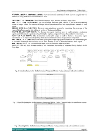
The environment is created as shown in the fig. 1 and fig. 5 respectively using Simulink tool.
RANDOM INTEGER GENERATOR: The random integer generator generates random uniformly distributed
integers in the range [0, M-1], where M is the M-ary number. INTEGER TO BIT CONVERTER: In the integer
to bit convertor unit, a vector of integer-valued or fixed valued type is mapped to a vector of bits. The number of
bits per integer parameter value present in the integer to bit convertor block defines how many bits are mapped
for each integer-valued input. For fixed-point inputs, the stored integer value is used. This block is single-rated
and so the input can be either a scalar or a frame-based column vector. For sample-based scalar input, the output
is a 1-D signal with ‘Number if bits per integer’ elements. For frame-based column vector input, the output is a
column vector with length equal to ‘Number of bits per integer’ times larger than the input signal length.
DIFFERENTIAL ENCODER: Differential encoder differentially encodes the input data. The differential
encoder object encodes the binary input signal within a channel. The output is the logical difference between the
current input element and the previous output element.
CONVOLUTIONAL INTERLEAVER: This block permutes the symbols in the input signal. Internally, it
uses a set of shift registers. The delay value of the kth shift register is (k-1) times the register length
step parameter. The number of shift registers is the value of the rows of shift registers parameter.
QAM MODULATOR BASEBAND: This block modulates the input signal using the quadrature amplitude
modulation method. The block only accepts integers as input.
QAM DEMODULATOR BASEBAND: This block demodulates the input signal using the quadrature
amplitude modulation method. For sample-based input, the input must be a scalar. For frame-based input, the
input must be a column vector.BUFFER: The buffer converts scalar samples to a frame output at a lower sample
rate. The conversion of a frame to a larger size or smaller size with optional overlap is possible. It is then passed
to the multipath Rician fading](https://image.slidesharecdn.com/i035456062-130614014143-phpapp02/85/I035456062-4-320.jpg)
![Performance Comparison Of Rayleigh…
www.ijceronline.com ||May ||2013|| Page 62
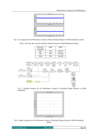
Fig. 7. Scatter plot for the Performance Analysis of Rayleigh Fading Channels in QAM modulation scheme
Fig. 8. Eye diagram for the Performance Analysis of Rayleigh Fading Channels in QAM modulation scheme
Table 2. Bit Error Rate Analysis of Rayleigh Fading Channels in QAM Modulation Scheme
SNR BER
300 0.02020
400 0.01648
500 0.01123
IV. CONCLUSIONS
An introduction to the line of sight transmission followed by a review on Rayleigh and Rician fading
channels is provided. It is apparent from table 1 that when the Ricean factor and Signal to Noise Ratio
increases, the Bit Error Rate decreases gradually. Similarly from table 2 it can be inferred that when the Signal
to Noise ratio increases, the Bit Error Rate decreases. It is observed from table 1 and table 2 that for a very high
SNR a low bit error rate is achieved. The Quadrature Amplitude Modulation scheme can produce a very low bit
error rate for the same signal to noise ratio in Rayleigh fading channels than in the Ricean fading channels.
Future works may include the effective use of different modulation schemes in the Simulink scenario to produce
a very low bit error rate.
REFERENCES
[1] L.Hanzo, M.Munster, B.J.Choi and T.Keller, OFDM and MC-CDMA for Broadband Multi-User Communications, WLANs and
Broadcasting (New York: Wiley-IEEE, 2003)
[2] S.L.Cotton and S.G.Scanlon, Characterization and modeling of the indoor radio cannel at 868 MHz for a mobile bodyworn
wireless personal area network, IEEE Anten. Propagat. Lett., 6:1(2007), 51-55.
[3] K.Davies and E.K.Smith, Ionospheric effects on satellite land mobile systems. IEEE Antenn. Propagat. Mag., 44:6 (2002), 24-
31.
[4] Q.V.Davis and D.J.R.Martin, and R.W.Haining, Microwave radio in mines and tunnels. In Proc. IEEE VTC, Pittsburgh, PA, May
1984, 31-36.
[5] V.Erceg, L.J.Greenstein , S.Y.Tjandra, S.R.Parkoff, A.Gupta, B.Kulic, A.A.Julius and R.Bianchi, An empirically based pathloss
model for wireless channels in suburban environments. IEEE J.Sel. Areas Commun., 17:7 (1999), 1205-1211.
[6] A.Goldsmith, Wireless Communications (Cambridge, UK:Cambridge University Press, 2005).](https://image.slidesharecdn.com/i035456062-130614014143-phpapp02/85/I035456062-7-320.jpg)


![Getting Started with Apache Spark: Big Data Made Simple [Free Meetup]](https://cdn.slidesharecdn.com/ss_thumbnails/apachesparkgettingstarted-260203175547-8361bcc3-thumbnail.jpg?width=640&height=640&fit=bounds)


