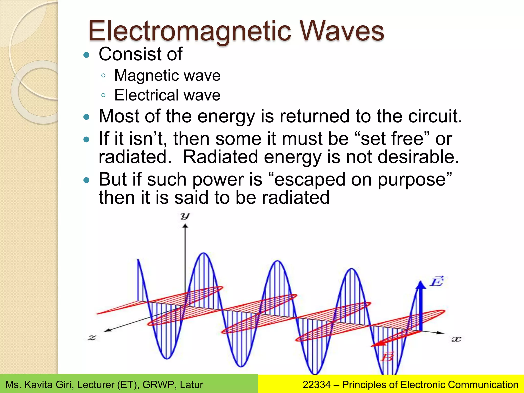
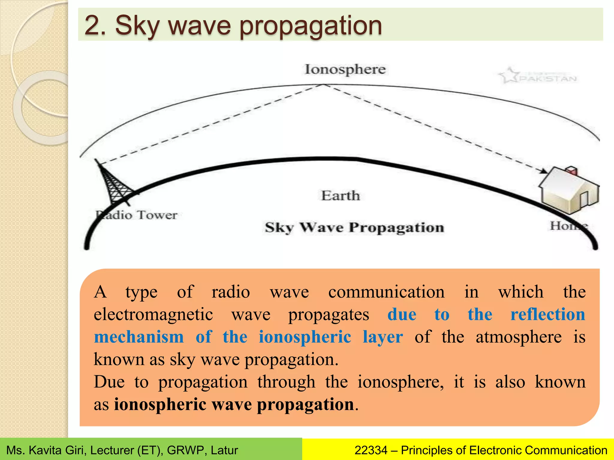
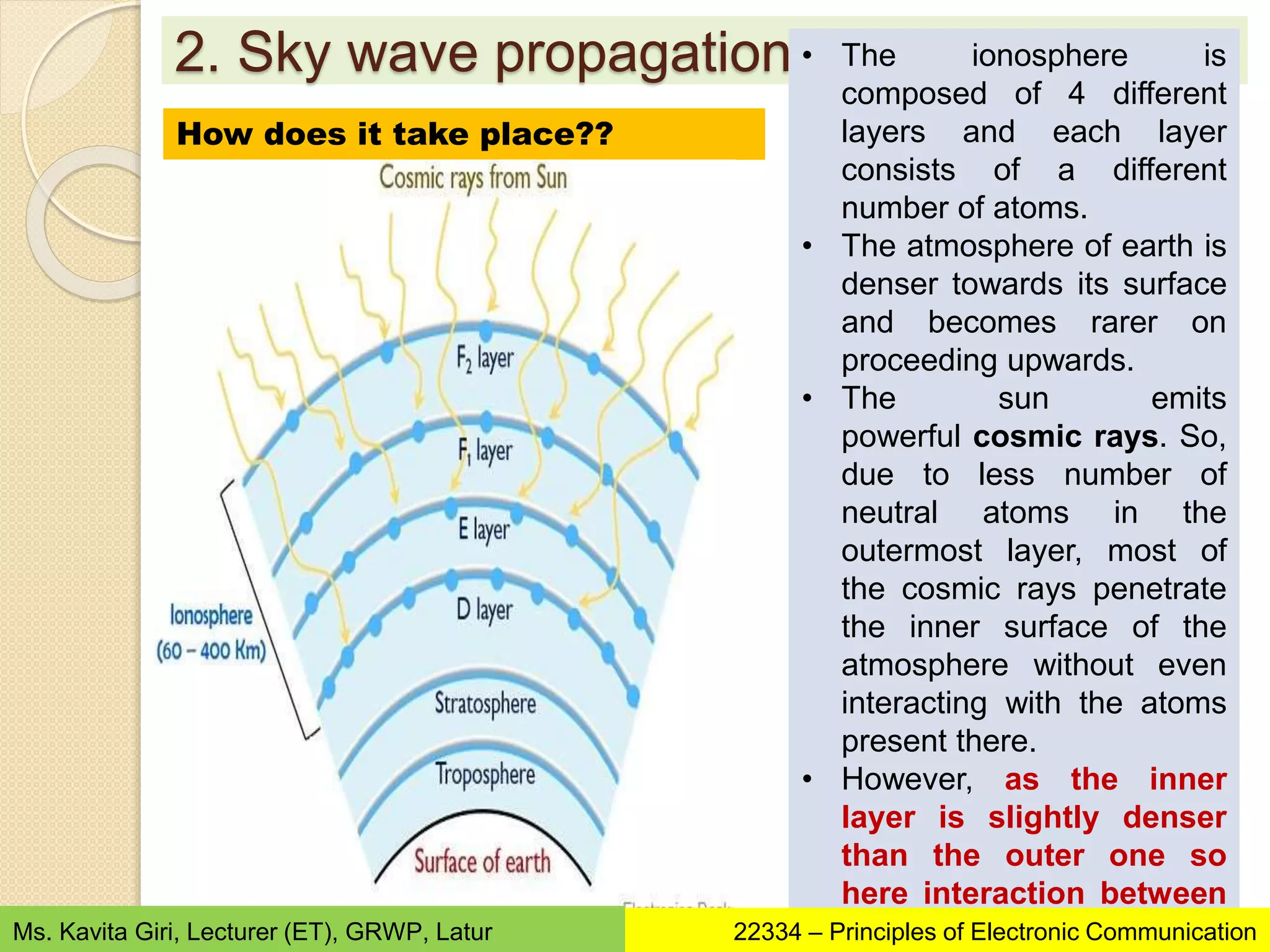
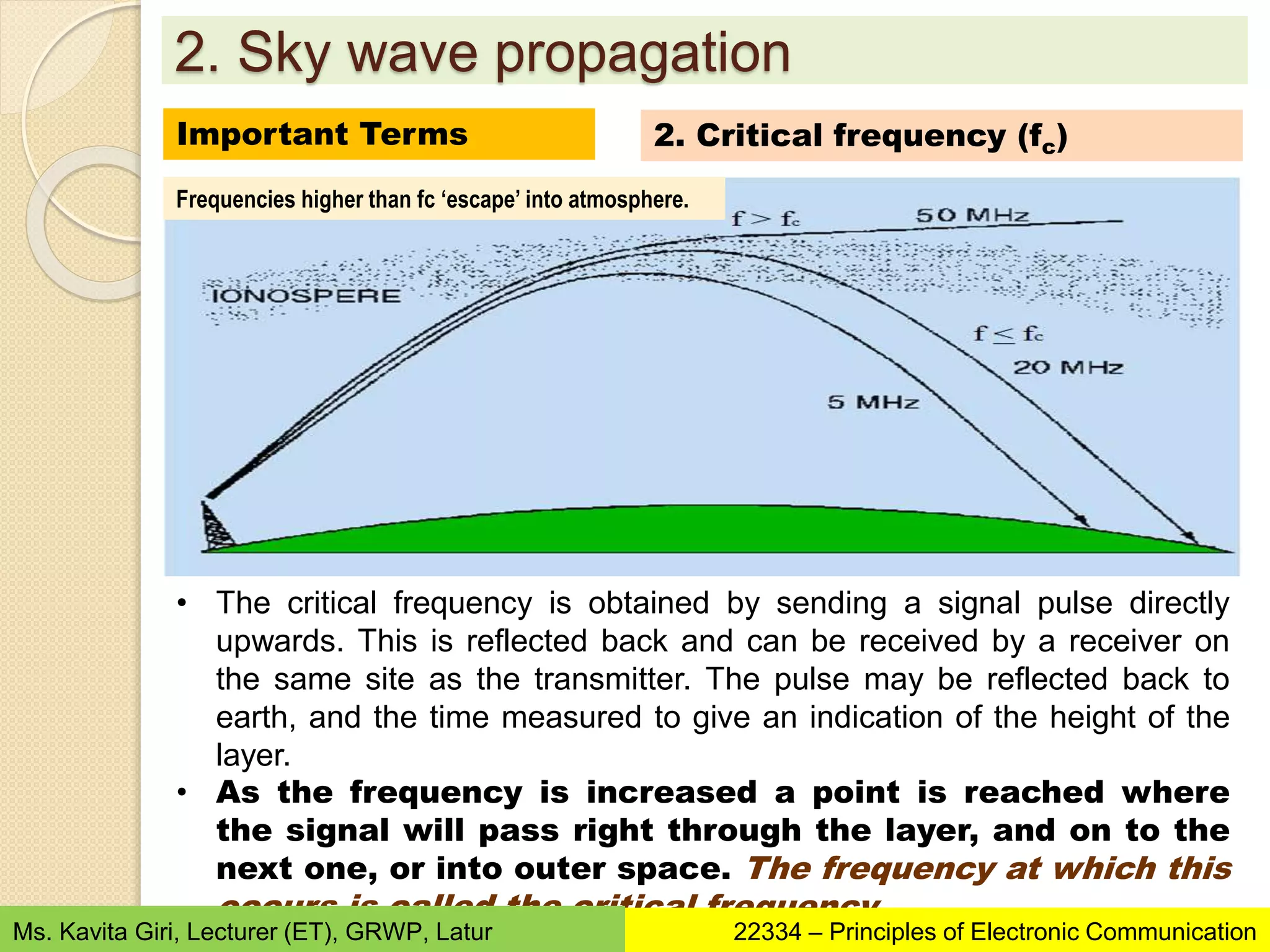
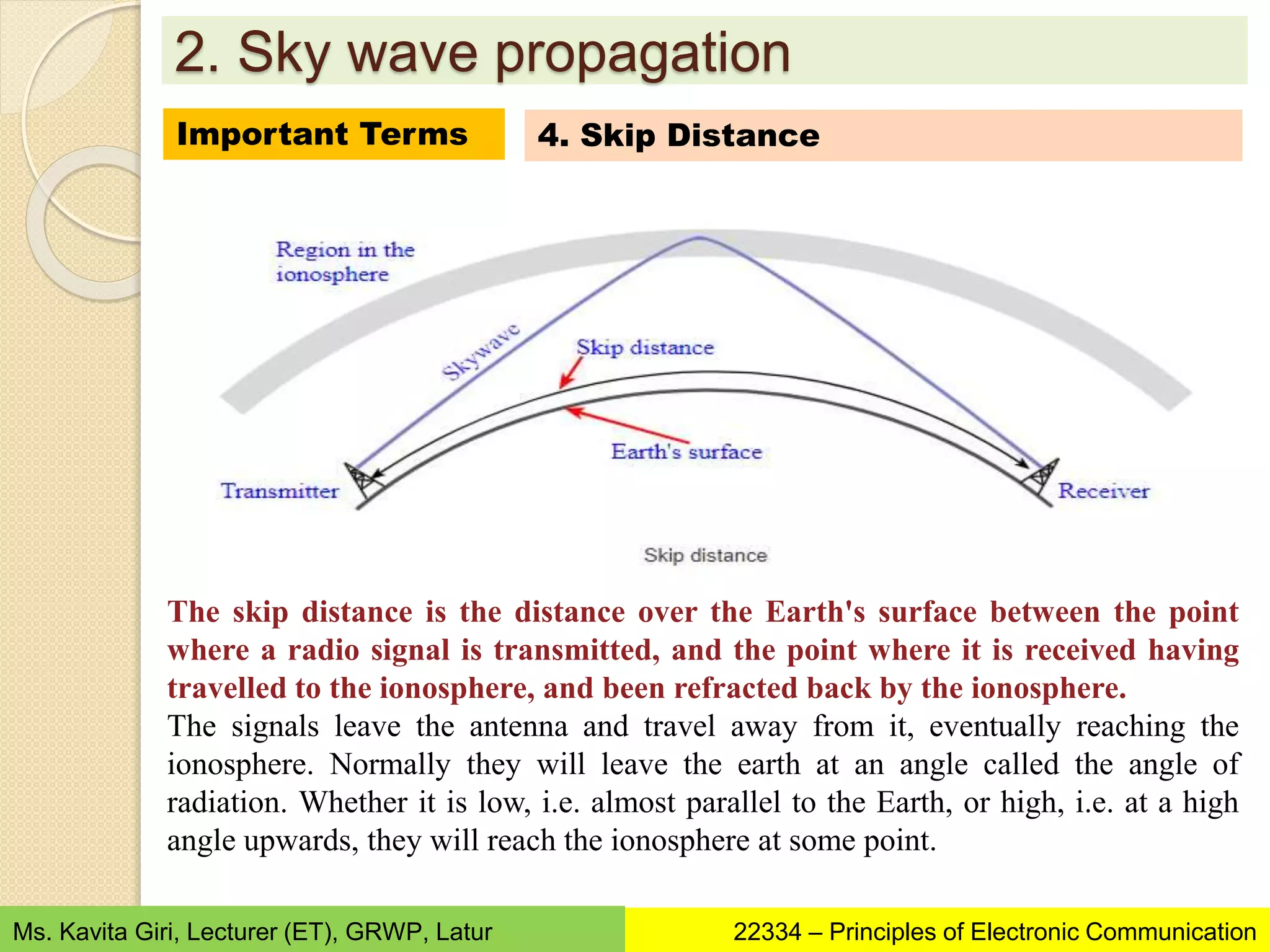
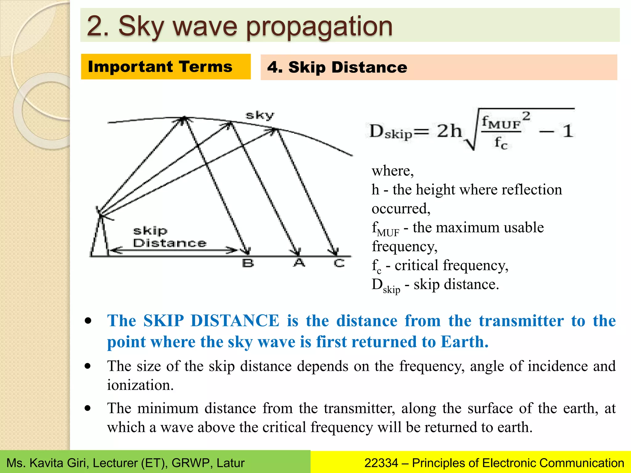
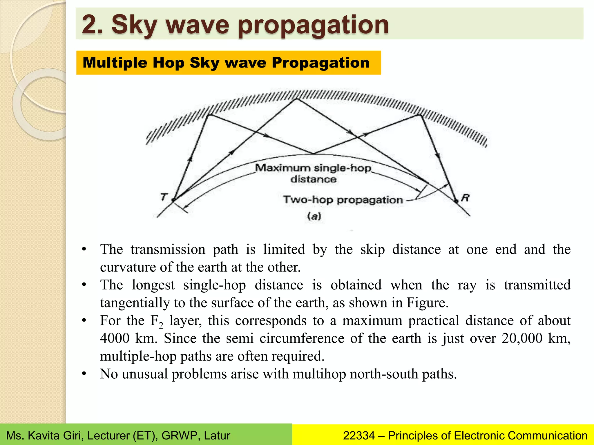
Chapter 4
WAVE PROPAGATION
10 Hours
14 Marks
Learning Outcomes
1. Describe the properties of given types of
electromagnetic waves.
2. Describe with sketches propagation mode of given
type of radio wave.
3. Describe properties of specified ionospheric layer.
4. Explain parameters and properties of give type of
wave propagation.
5. For the given application, identify the type of wave
propagation to be used with justification.
22334 – Principles of Electronic Communication
Ms. Kavita Giri, Lecturer (ET), GRWP, Latur
Contents
4.1 Concept of propagation of radio waves
4.2 Ground wave propagation
4.3 Sky wave: Ionospheric layers, concept of actual height
and virtual height, Critical frequency, Skip distance, skip
zone, concept of fading, maximum usable frequency,
multiple hop sky wave propagation.
4.4 Space wave propagation: line of sight, multipath space
wave propagation, optical and radio horizon, shadow zones
4.5 Duct wave propagation
4.6 Tropospheric scatter propagation
22334 – Principles of Electronic Communication
Ms. Kavita Giri, Lecturer (ET), GRWP, Latur
Introduction
 The signals transmitted by a transmitter will travel
through the channel to the receiver.
 In wireless radio communication, this channel is nothing
but free space.
 The process of signal travel from transmitter to receiver
can be divided as:
◦ Radiation
◦ Propagation
22334 – Principles of Electronic Communication
Ms. Kavita Giri, Lecturer (ET), GRWP, Latur
Introduction
Radiation
• Whenever a HF current
flows through a
conductor, the power
measured on both sides
of conductor is not same.
• A part of power is
dissipated in the
resistance and a part of it
‘escapes’ into the free
space.
• This ‘escape’ is radiation.
Propagation
• This radiated power then
propagates in space in
the form of
electromagnetic waves
• The radiation and
propagation of radio
waves cannot be seen.
22334 – Principles of Electronic Communication
Ms. Kavita Giri, Lecturer (ET), GRWP, Latur
Wave
 Wave is a mode of transfer of energy
◦ Transverse waves
◦ Longitudinal waves
22334 – Principles of Electronic Communication
Ms. Kavita Giri, Lecturer (ET), GRWP, Latur
Transverse Waves
 Transverse waves are those whose direction of
propagation is perpendicular to both the
electrical field and the magnetic field The
electrical field and the magnetic fields lie in
planes that are perpendicular to each other. (x
and y planes)
 Thus the direction of propagation will be in the
z plane or third dimension
22334 – Principles of Electronic Communication
Ms. Kavita Giri, Lecturer (ET), GRWP, Latur
Electromagnetic Waves
 Consist of
◦ Magnetic wave
◦ Electrical wave
 Most of the energy is returned to the circuit.
 If it isn’t, then some it must be “set free” or
radiated. Radiated energy is not desirable.
 But if such power is “escaped on purpose”
then it is said to be radiated
22334 – Principles of Electronic Communication
Ms. Kavita Giri, Lecturer (ET), GRWP, Latur
Wave Propagation Example
electric
field
magnetic
field
propagation direction
22334 – Principles of Electronic Communication
Ms. Kavita Giri, Lecturer (ET), GRWP, Latur
Properties of radio waves
2. Refraction
• Analogous to
Bending
1. Reflection
• Analogous to
Bouncing
3. Diffraction
• Analogous to
Scattering
4. Interference
• Analogous to
Colliding
22334 – Principles of Electronic Communication
Ms. Kavita Giri, Lecturer (ET), GRWP, Latur
1. Reflection
 Reflection of waves from a smooth surface (specular
reflection) results in the angle of reflection being equal to
the angle of incidence
Properties of radio waves
22334 – Principles of Electronic Communication
Ms. Kavita Giri, Lecturer (ET), GRWP, Latur
1. Reflection
 Reflection of waves from a smooth surface (specular
reflection) results in the angle of reflection being equal to
the angle of incidence
Properties of radio waves
22334 – Principles of Electronic Communication
Ms. Kavita Giri, Lecturer (ET), GRWP, Latur
Other Types of Reflection
Corner reflector
1. Reflection
Properties of radio waves
Parabolic reflector
22334 – Principles of Electronic Communication
Ms. Kavita Giri, Lecturer (ET), GRWP, Latur
Other Types of Reflection
Diffused Reflection
1. Reflection
Properties of radio waves
22334 – Principles of Electronic Communication
Ms. Kavita Giri, Lecturer (ET), GRWP, Latur
2. Refraction
 A transition from one
medium to another
results in the bending of
radio waves, just as it
does with light
 Snell’s Law governs the
behavior of
electromagnetic waves
being refracted:
n1 sin1  n2 sin2
Properties of radio waves
22334 – Principles of Electronic Communication
Ms. Kavita Giri, Lecturer (ET), GRWP, Latur
2. Refraction
Properties of radio waves
22334 – Principles of Electronic Communication
Ms. Kavita Giri, Lecturer (ET), GRWP, Latur
3. Diffraction
 As a result of
diffraction,
electromagnetic waves
can appear to “go
around corners”
 Diffraction is more
apparent when the
object has sharp edges,
that is when the
dimensions are small
in comparison to the
wavelength
Properties of radio waves
22334 – Principles of Electronic Communication
Ms. Kavita Giri, Lecturer (ET), GRWP, Latur
4. Interference
 Interference – occurs when 2 or more
waves overlap
◦ constructive interference  2 or more waves
combine to produce a wave with larger
displacement Constructive - louder
Properties of radio waves
22334 – Principles of Electronic Communication
Ms. Kavita Giri, Lecturer (ET), GRWP, Latur
 Destructive interference  2 or more waves
combine to produce a wave with smaller
displacement Destructive - softer
4. Interference
Properties of radio waves
22334 – Principles of Electronic Communication
Ms. Kavita Giri, Lecturer (ET), GRWP, Latur
4. Interference
Properties of radio waves
22334 – Principles of Electronic Communication
Ms. Kavita Giri, Lecturer (ET), GRWP, Latur
Propagation of EM waves
 Once the signal leaves the antenna, (i.e.,
radiated) it can take any of the three paths
Frequen
cy
Space wave
or (TV or FM
transmission)
Line of Sight Propagation
Sky
Wave (SW band in radio
broadcasting)
Propagation
Ground
Wave (MW band in radio)
Propagation
30 MHz
3 MHz
30 KHz
22334 – Principles of Electronic Communication
Ms. Kavita Giri, Lecturer (ET), GRWP, Latur
Propagation of EM waves
Three basic
paths that a
radio signal can
take
Ground wave
propagation
Along the surface of
Earth
Sky wave
Propagation
Up to the ionosphere
and back
Space wave
Propagation
From the transmitter to
receiver in a straight
line
Path taken by radio signal depends on
Frequency of
signal
Atmospheric
conditions
Time of the day
22334 – Principles of Electronic Communication
Ms. Kavita Giri, Lecturer (ET), GRWP, Latur
1. Ground wave propagation
The ground or surface wave leaves the antenna and remains close to
the earth. The ground wave will actually follow the curvature of the
earth and therefore can travel a distance beyond the horizon.
It is the strongest at the low and medium frequency ranges. The
ground waves is the path chosen by the signal when the frequency is
between 30 KHz and 3 MHz.
The ground waves must be vertically polarized to prevent short
circuiting of the electric field component. The EM waves are said to
be vertically polarized if all its electric intensity vectors are vertical.
22334 – Principles of Electronic Communication
Ms. Kavita Giri, Lecturer (ET), GRWP, Latur
1. Ground wave propagation
Attenuation of the Ground Waves:
• While passing over the earth surface, the ground waves induce
some current into it. Thus they lose some energy due to absorption.
• The tilt angle increases with increase in frequency, hence puts
a limitation on the range of transmission if the transmission
takes place near the top of the medium frequency range
(near 3 MHz).
Due to diffraction, the
wavefronts will gradually tilt
over as shown.
The angle of tilt goes on
increasing as the ground
waves progress over the
surface of the earth.
Eventually, the wave lies
down and dies.
22334 – Principles of Electronic Communication
Ms. Kavita Giri, Lecturer (ET), GRWP, Latur
1. Ground wave propagation
Advantages
• If transmitted power is large
enough, then ground wave
propagation can be used to
communicate between any two
parts of the world.
• The atmospheric conditions do
not affect the ground wave
propagation too much.
Disadvantages
• Limited range for higher
operating frequencies.
• At low operating frequencies,
very tall antennas should be
used.
• High transmission power is
necessary to cover the
adequate range..
Applications
1. AM radio broadcasting operating in MW band.
2. VLF transmission is used for ship communications such as radio
navigation and marine mobile communications.
22334 – Principles of Electronic Communication
Ms. Kavita Giri, Lecturer (ET), GRWP, Latur
2. Sky wave propagation
A type of radio wave communication in which the
electromagnetic wave propagates due to the reflection
mechanism of the ionospheric layer of the atmosphere is
known as sky wave propagation.
Due to propagation through the ionosphere, it is also known
as ionospheric wave propagation.
22334 – Principles of Electronic Communication
Ms. Kavita Giri, Lecturer (ET), GRWP, Latur
2. Sky wave propagation
1. Ground wave propagation is usually suitable for the
transmission of low-frequency electromagnetic
signals (usually up to 2 or 3 MHz).
2. Another major disadvantage associated with ground
wave propagation is that it is suitable only for short-
range operation. This is so because the induced
wave in ground wave propagation causes
attenuation of the propagated signal.
Need
22334 – Principles of Electronic Communication
Ms. Kavita Giri, Lecturer (ET), GRWP, Latur
2. Sky wave propagation
Ionosphere is present in the upper atmospheric region and is
composed of ionized layers.
Generally, the ionosphere consists of 4 different layers namely D,
E, F1, and F2.
These layers are present at different heights from the surface of
the earth.
Basically the ionosphere is said to be extended from 60 to 400
Km from the surface of the earth.
Ionosphere
22334 – Principles of Electronic Communication
Ms. Kavita Giri, Lecturer (ET), GRWP, Latur
2. Sky wave propagation
Each layer has a different concentration of atoms in a way
that the ionized layer which is present nearer to the surface
of the earth has the highest number of neutral atoms.
While the middle layer has moderate concentration and the
outermost layer consists of a very less number of neutral
atoms.
Ionosphere
22334 – Principles of Electronic Communication
Ms. Kavita Giri, Lecturer (ET), GRWP, Latur
• Average height 70km
• Average thickness 10km
• Its exists only in day time.
• It is not useful layer for HF communication
• It reflects some VLF and LF waves
• Its electron density N=400 electrons/cc
• fc=180kHz
• Almost no refraction (bending) of radio waves.
• Its virtual height is 60 to 80km.
31
2. Sky wave propagation
Ionosphere – The D - Layer
22334 – Principles of Electronic Communication
Ms. Kavita Giri, Lecturer (ET), GRWP, Latur
• Average height 100km
• Average thickness 25km
• Its exists only in day time
• It reflects some HF waves
• Its electron density N=5×10⁵ electrons/cc
• fc=4MHz
• Its virtual height is 110km
• Maximum single hop range 2,350km
32
2. Sky wave propagation
Ionosphere – The E - Layer
22334 – Principles of Electronic Communication
Ms. Kavita Giri, Lecturer (ET), GRWP, Latur
• Its exists in both day and night
• It is a thin layer
• Its height normally 90 to 130km
• Its electron density is high
• It is difficult to know where and when it will
occur and how long it will persist.
33
2. Sky wave propagation
Ionosphere – The Es - Layer
22334 – Principles of Electronic Communication
Ms. Kavita Giri, Lecturer (ET), GRWP, Latur
• Average height 180km
• Average thickness 20km
• It combines with F2 layer at night
• fc=5MHz
• Its virtual height is 180km
• Maximum single hop range 3,000km
• Although some HF waves get reflected from it,
most of them pass through it
• It affect HF waves by providing more absorption.
34
2. Sky wave propagation
Ionosphere – The F1 - Layer
• Average height 325km in day time
• Thickness is about 200km
• It falls to a height of 300km at nights as it
combines with F1 layer
• It offers better HF reflection
• Its electron density N=8×10¹¹ electrons/m3
• fc=8MHz in day & fc=6MHz in night
• Its virtual height is 300km
• Maximum single hop range 4,000km
2. Sky wave propagation
Ionosphere – The F2 - Layer
22334 – Principles of Electronic Communication
Ms. Kavita Giri, Lecturer (ET), GRWP, Latur
2. Sky wave propagation • The ionosphere is
composed of 4 different
layers and each layer
consists of a different
number of atoms.
• The atmosphere of earth is
denser towards its surface
and becomes rarer on
proceeding upwards.
• The sun emits
powerful cosmic rays. So,
due to less number of
neutral atoms in the
outermost layer, most of
the cosmic rays penetrate
the inner surface of the
atmosphere without even
interacting with the atoms
present there.
• However, as the inner
layer is slightly denser
than the outer one so
here interaction between
cosmic rays and atoms
How does it take place??
22334 – Principles of Electronic Communication
Ms. Kavita Giri, Lecturer (ET), GRWP, Latur
2. Sky wave propagation• So, when cosmic rays
interact with the atoms
present in the ionospheric
layers then electrons are
emitted from the valence
shell of the atom.
Thus ionization takes
place.
• interaction is higher in the
case of middle layers of
the atmosphere, therefore,
ionization will be higher in
that layer itself.
• Thus it holds the maximum
number of charged
particles.
• Whenever an
electromagnetic signal is
transmitted from
an antenna then it
suffers reflection from
the ionospheric layer and
comes back to the
surface of the earth and
How does it take place??
22334 – Principles of Electronic Communication
Ms. Kavita Giri, Lecturer (ET), GRWP, Latur
2. Sky wave propagation
How does it take place?? When the transmitting
antenna transmits the
electromagnetic wave
with a certain angle
(equal or greater than
critical angle) then due
to ionization on the
earth’s atmosphere it
gets reflected back
towards the surface of
the earth.
This causes the
reception of the
reflected signals by
the receiving antenna.
22334 – Principles of Electronic Communication
Ms. Kavita Giri, Lecturer (ET), GRWP, Latur
2. Sky wave propagation
How does it take place??
When light propagates from a denser to a rarer medium with an
angle equal to or greater than a critical angle then it gets reflected
back towards the same medium. This is referred as Total Internal
Reflection.
22334 – Principles of Electronic Communication
Ms. Kavita Giri, Lecturer (ET), GRWP, Latur
2. Sky wave propagation
How does it take place??
• Electromagnetic waves are composed of electric and magnetic fields.Also, the
charged particles present in the layers of the ionosphere have their own
electric field. So, when EMW is allowed to be propagated through the earth’s
atmosphere then the field of the EMW and the charged particles interact with
each other. And this leads to cause reflection of the electromagnetic wave by
the atmosphere.
• More simply we can say this as TIR taking place in the atmosphere.
• However, with upward movement, even the high-frequency wave will get
reflected due to a higher degree of ionization.
• So, we can say this as a low-frequency wave is reflected by the lower layer
and the high-frequency wave is reflected by the upper layer. But beyond a
certain permissible frequency (generally 30 MHz) the wave despite
getting reflected penetrates the atmospheric region and is lost.
• Hence sky wave propagation is suitable for the frequency range from 3MHz
to 30 MHz. But for signal frequency greater than 30 MHz, space wave
propagation is used.
•
22334 – Principles of Electronic Communication
Ms. Kavita Giri, Lecturer (ET), GRWP, Latur
2. Sky wave propagation Why do we get better reception at night?
• At night, F1 and F2 layers combine to form one layer and the lower two layers
D and E disappear.
• As the lower layers are absent, the absorption of the signal does not take place,
which was taking place during the day time.
• This improves the strength of reflected signal and hence the quality of
reception at night.
22334 – Principles of Electronic Communication
Ms. Kavita Giri, Lecturer (ET), GRWP, Latur
2. Sky wave propagation
Important Terms
As the wave is refracted, it is bent
down gradually rather than sharply.
However, below the ionized layer, the
incident and refracted rays follow
paths that are exactly the same as
they would have been if reflection
had taken place from a surface
located at a greater height, called the
virtual height of this layer.
1. Virtual Height
It is the height from which
the radio wave appears
to be reflecting.
Virtual height > Actual
height
22334 – Principles of Electronic Communication
Ms. Kavita Giri, Lecturer (ET), GRWP, Latur
2. Sky wave propagation
Important Terms
• The critical frequency is obtained by sending a signal pulse directly
upwards. This is reflected back and can be received by a receiver on
the same site as the transmitter. The pulse may be reflected back to
earth, and the time measured to give an indication of the height of the
layer.
• As the frequency is increased a point is reached where
the signal will pass right through the layer, and on to the
next one, or into outer space. The frequency at which this
occurs is called the critical frequency.
2. Critical frequency (fc)
Frequencies higher than fc ‘escape’ into atmosphere.
22334 – Principles of Electronic Communication
Ms. Kavita Giri, Lecturer (ET), GRWP, Latur
2. Sky wave propagation
Important Terms
• When a signal is transmitted using HF
propagation, over a given path there is a
maximum frequency that can be used. This
results from the fact that as the signal frequency
increases it will pass through more layers and
eventually travelling into outer space. As it
passes through one layer it may be that
communication is lost because the signal then
propagates over a greater distance than is
required. Also when the signal passes through
all the layers communication will be lost.
• The frequency at which radio
communications just starts to fail is known
as the Maximum Usable Frequency (MUF).
• As a rule of thumb it is generally three to five
times the critical frequency.
3. Maximum Usable Frequency (MUF)
22334 – Principles of Electronic Communication
Ms. Kavita Giri, Lecturer (ET), GRWP, Latur
2. Sky wave propagation
Important Terms
The skip distance is the distance over the Earth's surface between the point
where a radio signal is transmitted, and the point where it is received having
travelled to the ionosphere, and been refracted back by the ionosphere.
The signals leave the antenna and travel away from it, eventually reaching the
ionosphere. Normally they will leave the earth at an angle called the angle of
radiation. Whether it is low, i.e. almost parallel to the Earth, or high, i.e. at a high
angle upwards, they will reach the ionosphere at some point.
4. Skip Distance
22334 – Principles of Electronic Communication
Ms. Kavita Giri, Lecturer (ET), GRWP, Latur
2. Sky wave propagation
Important Terms
• The SKIP DISTANCE is the distance from the transmitter to the
point where the sky wave is first returned to Earth.
• The size of the skip distance depends on the frequency, angle of incidence and
ionization.
• The minimum distance from the transmitter, along the surface of the earth, at
which a wave above the critical frequency will be returned to earth.
4. Skip Distance
where,
h - the height where reflection
occurred,
fMUF - the maximum usable
frequency,
fc - critical frequency,
Dskip - skip distance.
22334 – Principles of Electronic Communication
Ms. Kavita Giri, Lecturer (ET), GRWP, Latur
2. Sky wave propagation
Important Terms 5. Skip Zone
• The skip zone, which may also be called a silent zone or dead zone, is
a region where radio transmission can not be received.
• The skip zone is the region between the point where the ground wave
signals can no longer be heard and the point where the skywave
first returns to Earth.
22334 – Principles of Electronic Communication
Ms. Kavita Giri, Lecturer (ET), GRWP, Latur
2. Sky wave propagation
Fading
22334 – Principles of Electronic Communication
Ms. Kavita Giri, Lecturer (ET), GRWP, Latur
• Fading is defined as the fluctuation in the strength of the
signal received at the receiver.
• These are basically unwanted variations introduced at the
time when the signal propagates from an end to another
by taking multiple paths.
• Fading is a gradual phenomenon and signal can be
recovered.
• However, the fade-out is a phenomenon which is a
condition of sudden ionospheric disturbance or ionospheric
storms in sunspot cycles, etc. that leads to complete fading
of the signal.
2. Sky wave propagation
Fading
22334 – Principles of Electronic Communication
Ms. Kavita Giri, Lecturer (ET), GRWP, Latur
Fading
Frequency
selective
fading
Interference
Fading
2. Sky wave propagation
1. Frequency selective Fading
22334 – Principles of Electronic Communication
Ms. Kavita Giri, Lecturer (ET), GRWP, Latur
• Basically when waves propagate through different paths by being
reflected from various man-made entities then the different
frequencies get affected to different degrees.
• This will lead to cause variation in the amplitude and phase of the
signals to a different extent while propagating in the channel.
• It is to be noted that even if the path length through which the signal is
propagating is same, then also the signals will possess different
wavelengths. This causes variation in the phase of the signal across
the overall bandwidth.
• Selective fading can occur over a quite large range of frequencies.
Suppose signals are utilizing ground wave propagation and sky wave
propagation, then in such case the phase of the signals will change
with time as the two are using two different medium of propagation.
2. Sky wave propagation
1. Frequency selective Fading
22334 – Principles of Electronic Communication
Ms. Kavita Giri, Lecturer (ET), GRWP, Latur
• Thus combinely when the signals are received at the
receiving antenna then there will be changes in the
received signal from the actually transmitted one.
• So, as this type of fading is frequency selective, thus at
the time of propagation, even adjacent parts of the signal
fade independently even if their frequency of separation is
small.
• Hence we can say, this causes severe distortion of the
modulated signal.
• As it severely affects high-frequency signals thus is more
dangerous in case of sky wave propagation. The
amplitude modulated signals are generally more prone to
such distortions rather than SSB signals.
• Thus one can use SSB systems to reduce selective
fading.
2. Sky wave propagation
2. Interference Fading
22334 – Principles of Electronic Communication
Ms. Kavita Giri, Lecturer (ET), GRWP, Latur
• Interference fading is also a result of the multipath
propagation of signals transmitted from the antenna.
• It occurs when waves interfere at the channel while
propagating from an end to another.
• Suppose a signal is propagated through sky wave
propagation, then the waves travel by getting reflected
from the upper and lower regions of the ionosphere.
• Sometimes the waves propagate through single or multiple
hops also, in case of low-frequency signals. Thereby
leading to cause interference of signals in the channel.
2. Sky wave propagation
2. Interference Fading
22334 – Principles of Electronic Communication
Ms. Kavita Giri, Lecturer (ET), GRWP, Latur
• Here ray ‘a’ is reflected from E layer,
• ray ‘b’ is reflected from F layer,
• ray ‘c’ is multihop propagation and
• ray ‘d’ is ground wave.
2. Sky wave propagation
Multiple Hop Sky wave Propagation
22334 – Principles of Electronic Communication
Ms. Kavita Giri, Lecturer (ET), GRWP, Latur
2. Sky wave propagation
Multiple Hop Sky wave Propagation
22334 – Principles of Electronic Communication
Ms. Kavita Giri, Lecturer (ET), GRWP, Latur
2. Sky wave propagation
Multiple Hop Sky wave Propagation
22334 – Principles of Electronic Communication
Ms. Kavita Giri, Lecturer (ET), GRWP, Latur
• The transmission path is limited by the skip distance at one end and the
curvature of the earth at the other.
• The longest single-hop distance is obtained when the ray is transmitted
tangentially to the surface of the earth, as shown in Figure.
• For the F2 layer, this corresponds to a maximum practical distance of about
4000 km. Since the semi circumference of the earth is just over 20,000 km,
multiple-hop paths are often required.
• No unusual problems arise with multihop north-south paths.
2. Sky wave propagation
Multiple Hop Sky wave Propagation
22334 – Principles of Electronic Communication
Ms. Kavita Giri, Lecturer (ET), GRWP, Latur
• However, care must be taken when planning long east-west paths to realise
that although it is day “here,” it is night “there,” if “there” happens to be on the
other side of the terminator.
• The result of not taking this into account is shown in Figure b.
• A path calculated on the basis of a constant height of the F2 layer will, if it
crosses the terminator, undershoot and miss the receiving area as shown the F
layer over the target is lower than the F2 layer over the transmitter.
3. Space wave propagation
22334 – Principles of Electronic Communication
Ms. Kavita Giri, Lecturer (ET), GRWP, Latur
• Space wave propagation is the type of radio wave
propagation in which the radio waves are propagated
either directly from transmitting antenna to receiving
antenna or by getting reflected from the ground.
• Basically in space wave propagation, direct
transmission of the signal is achieved by line of sight
communication.
• The transmission of a signal between transmitter and receiver is
achieved in the tropospheric region of the atmosphere. Thus space
wave propagation is sometimes referred as tropospheric wave
propagation.
• This type of radio wave propagation allows the transmission of signals
having a very large range of frequencies.
• Usually, it permits the transmission of signals having a frequency
greater than 30 MHz.
3. Space wave propagation
22334 – Principles of Electronic Communication
Ms. Kavita Giri, Lecturer (ET), GRWP, Latur
3. Space wave propagation
22334 – Principles of Electronic Communication
Ms. Kavita Giri, Lecturer (ET), GRWP, Latur
• In space wave propagation, the electromagnetic
waves are propagated when a direct path of
communication is present between the sender and
receiver. Sometimes the waves are transmitted by
getting reflected from the ground.
• The radio waves with extremely high frequencies are
known as space waves. The troposphere allows the
propagation of such waves.
• Generally, the troposphere is extended up to 10 to 20
km above the surface of the earth. Thus space wave
propagation occurs at about 20 km region in the
atmospheric zone.
• Sometimes called the line of sight communication.
This is so because such high-frequency waves
require a direct path for propagation.
3. Space wave propagation
22334 – Principles of Electronic Communication
Ms. Kavita Giri, Lecturer (ET), GRWP, Latur
• It is the farthest point that can be seen by the
transmitting antenna.
• If the space waves travel truly in a straight line then the
maximum range of space wave communication would be
limited to the optical horizon.
Optical Horizon
3. Space wave propagation
22334 – Principles of Electronic Communication
Ms. Kavita Giri, Lecturer (ET), GRWP, Latur
• It is the farthest point at which the radio wave can
travel.
• It is slightly greater than the optical horizon.
• It is greater due to the varying density of atmosphere and
because of the diffraction around the curvature of the Earth.
Radio Horizon
3. Space wave propagation
22334 – Principles of Electronic Communication
Ms. Kavita Giri, Lecturer (ET), GRWP, Latur
• Since the space waves travel very close to the ground, any tall or
massive objects such as hills, buildings, trees etc will obstruct the
space waves.
• These objects will absorb as well as scatter energy. Hence,
shadow zones are formed.
• The signal strength is very low in these zones therefore the
receiving antennas need to be taller to receive adequate amount
of signal.
Shadow Zones
3. Space wave propagation
22334 – Principles of Electronic Communication
Ms. Kavita Giri, Lecturer (ET), GRWP, Latur
1. TV broadcasting
2. FM radio broadcasting
3. Microwave Links
4. Satellite Communication
Applications
Duct propagation
22334 – Principles of Electronic Communication
Ms. Kavita Giri, Lecturer (ET), GRWP, Latur
Need
• Due to high frequency, the signals in the troposphere require
an obstruction-free path as wavelengths of such high-
frequency signals are short. Thus this mode of propagation
limits the range for signal transmission.
• So, for UHF and VHF signal transmission to an even greater
distance, the duct present in the tropospheric region of the
atmosphere is utilized.
• This duct acts as a channel to guide the high-frequency wave
to the other end by successive refraction. Hence is referred as
super refraction.
Duct propagation
22334 – Principles of Electronic Communication
Ms. Kavita Giri, Lecturer (ET), GRWP, Latur
What is an atmospheric duct?
• The atmospheric duct is the region or layer present in the lower
atmosphere, which is a result of temperature inversion.
• The duct behaves as a waveguide in the atmosphere and guides the
radio waves along the curvature of the earth thereby allowing the
spreading of wavefronts in a horizontal manner only.
Duct propagation
22334 – Principles of Electronic Communication
Ms. Kavita Giri, Lecturer (ET), GRWP, Latur
• We know that in a standard atmosphere, the temperature
shows reduction with height. This means with the upward
movement in the atmosphere the dielectric constant must
decrease uniformly.
• So, this will lead to have unity dielectric constant in the region
of zero air density. However, practically this standard
atmospheric condition shows rare existence.
• The reason behind this is that the air is of turbulent nature, also
there exist different layers of air. These multiple layers of air
contain different water vapor contents thus different
temperatures.
• So, the property of significantly having a decrease in
temperature with height gets failed to be achieved.
• This leads to the development of an unusual situation in the
atmosphere, where a layer of warm air exists above the cool air.
• This is known as temperature inversion and this gives rise to
the phenomenon of super refraction in the atmosphere.
What is temperature inversion?
Duct propagation
22334 – Principles of Electronic Communication
Ms. Kavita Giri, Lecturer (ET), GRWP, Latur
• Duct propagation is the phenomenon of transmitting UHF and
VHF signals to longer distances.
• The presence of a layer of cool air between warm air, generates
a duct that guides the high-frequency signals inside it like a
waveguide.
Duct propagation
22334 – Principles of Electronic Communication
Ms. Kavita Giri, Lecturer (ET), GRWP, Latur
• For duct propagation to take place, the two
necessary conditions are as follows:
1. The transmitting antenna must be extended up to
the region of the duct in the atmosphere and
2. The angle of incidence of radio waves should be
less than the value of the critical angle.
Duct propagation
22334 – Principles of Electronic Communication
Ms. Kavita Giri, Lecturer (ET), GRWP, Latur
• Warm and cool airs possess variation in the refractive index. This is
due to the variation in their densities.
• So, when such high-frequency wave emitted from the transmitting
antenna in the region of the duct (i.e., cool air) with a low angle of
incidence, then on experiencing lower refractive index from the region
of warm air due to lower density, the wave gets refracted back to the
surface of the earth.
• The air above the surface of the earth has a higher temperature, thus
the warm region is present lower next to the duct.
• So, the wave while propagating through the cool region (having higher
refractive index) towards the ground again gets refracted when
interacted with the medium of lower refractive index.
• This sudden variation in the refractive index of the medium is due to
the change in the dielectric constant of the atmosphere.
Duct propagation
22334 – Principles of Electronic Communication
Ms. Kavita Giri, Lecturer (ET), GRWP, Latur
• Due to this reason, the wave undergoes multiple
refractions and oscillates between the two
boundaries of the duct and received by the receiving
antenna.
• In this way, the transmitted signal gets achieved by
the antenna at the opposite end with less attenuation.
• In this way, duct propagation allows the transmission
of high-frequency signals to larger distances without
the condition of line of sight propagation.
• Through duct propagation, these high-frequency
signals can be transmitted up to a distance of 1000
km in the atmosphere.
•
Tropospheric Scatter propagation
22334 – Principles of Electronic Communication
Ms. Kavita Giri, Lecturer (ET), GRWP, Latur
Tropospheric Scatter propagation
22334 – Principles of Electronic Communication
Ms. Kavita Giri, Lecturer (ET), GRWP, Latur
• It is sometimes called forward scatter propagation or
scatter propagation and is suitable for VHF, UHF and
microwaves.
• In this, the waves propagate through forward
scattering due to the irregularities of the troposphere.
• This propagation technique uses the properties of the
troposphere. This mode offers reliable communication
between 160 km to 1600 km.
• It is called so because in this case, the propagation occurs
beyond the horizon i.e., the fine layers of the troposphere.
• This type of propagation sometimes leads to the
production of unwanted noise or fading.
Tropospheric Scatter propagation
22334 – Principles of Electronic Communication
Ms. Kavita Giri, Lecturer (ET), GRWP, Latur
• It is not affected by the
abnormal phenomena that
affect sky wave
propagation.
• Hence it is very reliable.
Advantages Applications
• Long distance
telephones
• Communication links
in inaccessible areas.
• Alternative to
microwave links or co-
axial cables.

Wave Propagation

  • 1.
  • 2.
    Learning Outcomes 1. Describethe properties of given types of electromagnetic waves. 2. Describe with sketches propagation mode of given type of radio wave. 3. Describe properties of specified ionospheric layer. 4. Explain parameters and properties of give type of wave propagation. 5. For the given application, identify the type of wave propagation to be used with justification. 22334 – Principles of Electronic Communication Ms. Kavita Giri, Lecturer (ET), GRWP, Latur
  • 3.
    Contents 4.1 Concept ofpropagation of radio waves 4.2 Ground wave propagation 4.3 Sky wave: Ionospheric layers, concept of actual height and virtual height, Critical frequency, Skip distance, skip zone, concept of fading, maximum usable frequency, multiple hop sky wave propagation. 4.4 Space wave propagation: line of sight, multipath space wave propagation, optical and radio horizon, shadow zones 4.5 Duct wave propagation 4.6 Tropospheric scatter propagation 22334 – Principles of Electronic Communication Ms. Kavita Giri, Lecturer (ET), GRWP, Latur
  • 4.
    Introduction  The signalstransmitted by a transmitter will travel through the channel to the receiver.  In wireless radio communication, this channel is nothing but free space.  The process of signal travel from transmitter to receiver can be divided as: ◦ Radiation ◦ Propagation 22334 – Principles of Electronic Communication Ms. Kavita Giri, Lecturer (ET), GRWP, Latur
  • 5.
    Introduction Radiation • Whenever aHF current flows through a conductor, the power measured on both sides of conductor is not same. • A part of power is dissipated in the resistance and a part of it ‘escapes’ into the free space. • This ‘escape’ is radiation. Propagation • This radiated power then propagates in space in the form of electromagnetic waves • The radiation and propagation of radio waves cannot be seen. 22334 – Principles of Electronic Communication Ms. Kavita Giri, Lecturer (ET), GRWP, Latur
  • 6.
    Wave  Wave isa mode of transfer of energy ◦ Transverse waves ◦ Longitudinal waves 22334 – Principles of Electronic Communication Ms. Kavita Giri, Lecturer (ET), GRWP, Latur
  • 7.
    Transverse Waves  Transversewaves are those whose direction of propagation is perpendicular to both the electrical field and the magnetic field The electrical field and the magnetic fields lie in planes that are perpendicular to each other. (x and y planes)  Thus the direction of propagation will be in the z plane or third dimension 22334 – Principles of Electronic Communication Ms. Kavita Giri, Lecturer (ET), GRWP, Latur
  • 8.
    Electromagnetic Waves  Consistof ◦ Magnetic wave ◦ Electrical wave  Most of the energy is returned to the circuit.  If it isn’t, then some it must be “set free” or radiated. Radiated energy is not desirable.  But if such power is “escaped on purpose” then it is said to be radiated 22334 – Principles of Electronic Communication Ms. Kavita Giri, Lecturer (ET), GRWP, Latur
  • 9.
    Wave Propagation Example electric field magnetic field propagationdirection 22334 – Principles of Electronic Communication Ms. Kavita Giri, Lecturer (ET), GRWP, Latur
  • 10.
    Properties of radiowaves 2. Refraction • Analogous to Bending 1. Reflection • Analogous to Bouncing 3. Diffraction • Analogous to Scattering 4. Interference • Analogous to Colliding 22334 – Principles of Electronic Communication Ms. Kavita Giri, Lecturer (ET), GRWP, Latur
  • 11.
    1. Reflection  Reflectionof waves from a smooth surface (specular reflection) results in the angle of reflection being equal to the angle of incidence Properties of radio waves 22334 – Principles of Electronic Communication Ms. Kavita Giri, Lecturer (ET), GRWP, Latur
  • 12.
    1. Reflection  Reflectionof waves from a smooth surface (specular reflection) results in the angle of reflection being equal to the angle of incidence Properties of radio waves 22334 – Principles of Electronic Communication Ms. Kavita Giri, Lecturer (ET), GRWP, Latur
  • 13.
    Other Types ofReflection Corner reflector 1. Reflection Properties of radio waves Parabolic reflector 22334 – Principles of Electronic Communication Ms. Kavita Giri, Lecturer (ET), GRWP, Latur
  • 14.
    Other Types ofReflection Diffused Reflection 1. Reflection Properties of radio waves 22334 – Principles of Electronic Communication Ms. Kavita Giri, Lecturer (ET), GRWP, Latur
  • 15.
    2. Refraction  Atransition from one medium to another results in the bending of radio waves, just as it does with light  Snell’s Law governs the behavior of electromagnetic waves being refracted: n1 sin1  n2 sin2 Properties of radio waves 22334 – Principles of Electronic Communication Ms. Kavita Giri, Lecturer (ET), GRWP, Latur
  • 16.
    2. Refraction Properties ofradio waves 22334 – Principles of Electronic Communication Ms. Kavita Giri, Lecturer (ET), GRWP, Latur
  • 17.
    3. Diffraction  Asa result of diffraction, electromagnetic waves can appear to “go around corners”  Diffraction is more apparent when the object has sharp edges, that is when the dimensions are small in comparison to the wavelength Properties of radio waves 22334 – Principles of Electronic Communication Ms. Kavita Giri, Lecturer (ET), GRWP, Latur
  • 18.
    3. Diffraction  Asa result of diffraction, electromagnetic waves can appear to “go around corners”  Diffraction is more apparent when the object has sharp edges, that is when the dimensions are small in comparison to the wavelength Properties of radio waves 22334 – Principles of Electronic Communication Ms. Kavita Giri, Lecturer (ET), GRWP, Latur
  • 19.
    4. Interference  Interference– occurs when 2 or more waves overlap ◦ constructive interference  2 or more waves combine to produce a wave with larger displacement Constructive - louder Properties of radio waves 22334 – Principles of Electronic Communication Ms. Kavita Giri, Lecturer (ET), GRWP, Latur
  • 20.
     Destructive interference 2 or more waves combine to produce a wave with smaller displacement Destructive - softer 4. Interference Properties of radio waves 22334 – Principles of Electronic Communication Ms. Kavita Giri, Lecturer (ET), GRWP, Latur
  • 21.
    4. Interference Properties ofradio waves 22334 – Principles of Electronic Communication Ms. Kavita Giri, Lecturer (ET), GRWP, Latur
  • 22.
    Propagation of EMwaves  Once the signal leaves the antenna, (i.e., radiated) it can take any of the three paths Frequen cy Space wave or (TV or FM transmission) Line of Sight Propagation Sky Wave (SW band in radio broadcasting) Propagation Ground Wave (MW band in radio) Propagation 30 MHz 3 MHz 30 KHz 22334 – Principles of Electronic Communication Ms. Kavita Giri, Lecturer (ET), GRWP, Latur
  • 23.
    Propagation of EMwaves Three basic paths that a radio signal can take Ground wave propagation Along the surface of Earth Sky wave Propagation Up to the ionosphere and back Space wave Propagation From the transmitter to receiver in a straight line Path taken by radio signal depends on Frequency of signal Atmospheric conditions Time of the day 22334 – Principles of Electronic Communication Ms. Kavita Giri, Lecturer (ET), GRWP, Latur
  • 24.
    1. Ground wavepropagation The ground or surface wave leaves the antenna and remains close to the earth. The ground wave will actually follow the curvature of the earth and therefore can travel a distance beyond the horizon. It is the strongest at the low and medium frequency ranges. The ground waves is the path chosen by the signal when the frequency is between 30 KHz and 3 MHz. The ground waves must be vertically polarized to prevent short circuiting of the electric field component. The EM waves are said to be vertically polarized if all its electric intensity vectors are vertical. 22334 – Principles of Electronic Communication Ms. Kavita Giri, Lecturer (ET), GRWP, Latur
  • 25.
    1. Ground wavepropagation Attenuation of the Ground Waves: • While passing over the earth surface, the ground waves induce some current into it. Thus they lose some energy due to absorption. • The tilt angle increases with increase in frequency, hence puts a limitation on the range of transmission if the transmission takes place near the top of the medium frequency range (near 3 MHz). Due to diffraction, the wavefronts will gradually tilt over as shown. The angle of tilt goes on increasing as the ground waves progress over the surface of the earth. Eventually, the wave lies down and dies. 22334 – Principles of Electronic Communication Ms. Kavita Giri, Lecturer (ET), GRWP, Latur
  • 26.
    1. Ground wavepropagation Advantages • If transmitted power is large enough, then ground wave propagation can be used to communicate between any two parts of the world. • The atmospheric conditions do not affect the ground wave propagation too much. Disadvantages • Limited range for higher operating frequencies. • At low operating frequencies, very tall antennas should be used. • High transmission power is necessary to cover the adequate range.. Applications 1. AM radio broadcasting operating in MW band. 2. VLF transmission is used for ship communications such as radio navigation and marine mobile communications. 22334 – Principles of Electronic Communication Ms. Kavita Giri, Lecturer (ET), GRWP, Latur
  • 27.
    2. Sky wavepropagation A type of radio wave communication in which the electromagnetic wave propagates due to the reflection mechanism of the ionospheric layer of the atmosphere is known as sky wave propagation. Due to propagation through the ionosphere, it is also known as ionospheric wave propagation. 22334 – Principles of Electronic Communication Ms. Kavita Giri, Lecturer (ET), GRWP, Latur
  • 28.
    2. Sky wavepropagation 1. Ground wave propagation is usually suitable for the transmission of low-frequency electromagnetic signals (usually up to 2 or 3 MHz). 2. Another major disadvantage associated with ground wave propagation is that it is suitable only for short- range operation. This is so because the induced wave in ground wave propagation causes attenuation of the propagated signal. Need 22334 – Principles of Electronic Communication Ms. Kavita Giri, Lecturer (ET), GRWP, Latur
  • 29.
    2. Sky wavepropagation Ionosphere is present in the upper atmospheric region and is composed of ionized layers. Generally, the ionosphere consists of 4 different layers namely D, E, F1, and F2. These layers are present at different heights from the surface of the earth. Basically the ionosphere is said to be extended from 60 to 400 Km from the surface of the earth. Ionosphere 22334 – Principles of Electronic Communication Ms. Kavita Giri, Lecturer (ET), GRWP, Latur
  • 30.
    2. Sky wavepropagation Each layer has a different concentration of atoms in a way that the ionized layer which is present nearer to the surface of the earth has the highest number of neutral atoms. While the middle layer has moderate concentration and the outermost layer consists of a very less number of neutral atoms. Ionosphere 22334 – Principles of Electronic Communication Ms. Kavita Giri, Lecturer (ET), GRWP, Latur
  • 31.
    • Average height70km • Average thickness 10km • Its exists only in day time. • It is not useful layer for HF communication • It reflects some VLF and LF waves • Its electron density N=400 electrons/cc • fc=180kHz • Almost no refraction (bending) of radio waves. • Its virtual height is 60 to 80km. 31 2. Sky wave propagation Ionosphere – The D - Layer 22334 – Principles of Electronic Communication Ms. Kavita Giri, Lecturer (ET), GRWP, Latur
  • 32.
    • Average height100km • Average thickness 25km • Its exists only in day time • It reflects some HF waves • Its electron density N=5×10⁵ electrons/cc • fc=4MHz • Its virtual height is 110km • Maximum single hop range 2,350km 32 2. Sky wave propagation Ionosphere – The E - Layer 22334 – Principles of Electronic Communication Ms. Kavita Giri, Lecturer (ET), GRWP, Latur
  • 33.
    • Its existsin both day and night • It is a thin layer • Its height normally 90 to 130km • Its electron density is high • It is difficult to know where and when it will occur and how long it will persist. 33 2. Sky wave propagation Ionosphere – The Es - Layer 22334 – Principles of Electronic Communication Ms. Kavita Giri, Lecturer (ET), GRWP, Latur
  • 34.
    • Average height180km • Average thickness 20km • It combines with F2 layer at night • fc=5MHz • Its virtual height is 180km • Maximum single hop range 3,000km • Although some HF waves get reflected from it, most of them pass through it • It affect HF waves by providing more absorption. 34 2. Sky wave propagation Ionosphere – The F1 - Layer
  • 35.
    • Average height325km in day time • Thickness is about 200km • It falls to a height of 300km at nights as it combines with F1 layer • It offers better HF reflection • Its electron density N=8×10¹¹ electrons/m3 • fc=8MHz in day & fc=6MHz in night • Its virtual height is 300km • Maximum single hop range 4,000km 2. Sky wave propagation Ionosphere – The F2 - Layer 22334 – Principles of Electronic Communication Ms. Kavita Giri, Lecturer (ET), GRWP, Latur
  • 36.
    2. Sky wavepropagation • The ionosphere is composed of 4 different layers and each layer consists of a different number of atoms. • The atmosphere of earth is denser towards its surface and becomes rarer on proceeding upwards. • The sun emits powerful cosmic rays. So, due to less number of neutral atoms in the outermost layer, most of the cosmic rays penetrate the inner surface of the atmosphere without even interacting with the atoms present there. • However, as the inner layer is slightly denser than the outer one so here interaction between cosmic rays and atoms How does it take place?? 22334 – Principles of Electronic Communication Ms. Kavita Giri, Lecturer (ET), GRWP, Latur
  • 37.
    2. Sky wavepropagation• So, when cosmic rays interact with the atoms present in the ionospheric layers then electrons are emitted from the valence shell of the atom. Thus ionization takes place. • interaction is higher in the case of middle layers of the atmosphere, therefore, ionization will be higher in that layer itself. • Thus it holds the maximum number of charged particles. • Whenever an electromagnetic signal is transmitted from an antenna then it suffers reflection from the ionospheric layer and comes back to the surface of the earth and How does it take place?? 22334 – Principles of Electronic Communication Ms. Kavita Giri, Lecturer (ET), GRWP, Latur
  • 38.
    2. Sky wavepropagation How does it take place?? When the transmitting antenna transmits the electromagnetic wave with a certain angle (equal or greater than critical angle) then due to ionization on the earth’s atmosphere it gets reflected back towards the surface of the earth. This causes the reception of the reflected signals by the receiving antenna. 22334 – Principles of Electronic Communication Ms. Kavita Giri, Lecturer (ET), GRWP, Latur
  • 39.
    2. Sky wavepropagation How does it take place?? When light propagates from a denser to a rarer medium with an angle equal to or greater than a critical angle then it gets reflected back towards the same medium. This is referred as Total Internal Reflection. 22334 – Principles of Electronic Communication Ms. Kavita Giri, Lecturer (ET), GRWP, Latur
  • 40.
    2. Sky wavepropagation How does it take place?? • Electromagnetic waves are composed of electric and magnetic fields.Also, the charged particles present in the layers of the ionosphere have their own electric field. So, when EMW is allowed to be propagated through the earth’s atmosphere then the field of the EMW and the charged particles interact with each other. And this leads to cause reflection of the electromagnetic wave by the atmosphere. • More simply we can say this as TIR taking place in the atmosphere. • However, with upward movement, even the high-frequency wave will get reflected due to a higher degree of ionization. • So, we can say this as a low-frequency wave is reflected by the lower layer and the high-frequency wave is reflected by the upper layer. But beyond a certain permissible frequency (generally 30 MHz) the wave despite getting reflected penetrates the atmospheric region and is lost. • Hence sky wave propagation is suitable for the frequency range from 3MHz to 30 MHz. But for signal frequency greater than 30 MHz, space wave propagation is used. • 22334 – Principles of Electronic Communication Ms. Kavita Giri, Lecturer (ET), GRWP, Latur
  • 41.
    2. Sky wavepropagation Why do we get better reception at night? • At night, F1 and F2 layers combine to form one layer and the lower two layers D and E disappear. • As the lower layers are absent, the absorption of the signal does not take place, which was taking place during the day time. • This improves the strength of reflected signal and hence the quality of reception at night. 22334 – Principles of Electronic Communication Ms. Kavita Giri, Lecturer (ET), GRWP, Latur
  • 42.
    2. Sky wavepropagation Important Terms As the wave is refracted, it is bent down gradually rather than sharply. However, below the ionized layer, the incident and refracted rays follow paths that are exactly the same as they would have been if reflection had taken place from a surface located at a greater height, called the virtual height of this layer. 1. Virtual Height It is the height from which the radio wave appears to be reflecting. Virtual height > Actual height 22334 – Principles of Electronic Communication Ms. Kavita Giri, Lecturer (ET), GRWP, Latur
  • 43.
    2. Sky wavepropagation Important Terms • The critical frequency is obtained by sending a signal pulse directly upwards. This is reflected back and can be received by a receiver on the same site as the transmitter. The pulse may be reflected back to earth, and the time measured to give an indication of the height of the layer. • As the frequency is increased a point is reached where the signal will pass right through the layer, and on to the next one, or into outer space. The frequency at which this occurs is called the critical frequency. 2. Critical frequency (fc) Frequencies higher than fc ‘escape’ into atmosphere. 22334 – Principles of Electronic Communication Ms. Kavita Giri, Lecturer (ET), GRWP, Latur
  • 44.
    2. Sky wavepropagation Important Terms • When a signal is transmitted using HF propagation, over a given path there is a maximum frequency that can be used. This results from the fact that as the signal frequency increases it will pass through more layers and eventually travelling into outer space. As it passes through one layer it may be that communication is lost because the signal then propagates over a greater distance than is required. Also when the signal passes through all the layers communication will be lost. • The frequency at which radio communications just starts to fail is known as the Maximum Usable Frequency (MUF). • As a rule of thumb it is generally three to five times the critical frequency. 3. Maximum Usable Frequency (MUF) 22334 – Principles of Electronic Communication Ms. Kavita Giri, Lecturer (ET), GRWP, Latur
  • 45.
    2. Sky wavepropagation Important Terms The skip distance is the distance over the Earth's surface between the point where a radio signal is transmitted, and the point where it is received having travelled to the ionosphere, and been refracted back by the ionosphere. The signals leave the antenna and travel away from it, eventually reaching the ionosphere. Normally they will leave the earth at an angle called the angle of radiation. Whether it is low, i.e. almost parallel to the Earth, or high, i.e. at a high angle upwards, they will reach the ionosphere at some point. 4. Skip Distance 22334 – Principles of Electronic Communication Ms. Kavita Giri, Lecturer (ET), GRWP, Latur
  • 46.
    2. Sky wavepropagation Important Terms • The SKIP DISTANCE is the distance from the transmitter to the point where the sky wave is first returned to Earth. • The size of the skip distance depends on the frequency, angle of incidence and ionization. • The minimum distance from the transmitter, along the surface of the earth, at which a wave above the critical frequency will be returned to earth. 4. Skip Distance where, h - the height where reflection occurred, fMUF - the maximum usable frequency, fc - critical frequency, Dskip - skip distance. 22334 – Principles of Electronic Communication Ms. Kavita Giri, Lecturer (ET), GRWP, Latur
  • 47.
    2. Sky wavepropagation Important Terms 5. Skip Zone • The skip zone, which may also be called a silent zone or dead zone, is a region where radio transmission can not be received. • The skip zone is the region between the point where the ground wave signals can no longer be heard and the point where the skywave first returns to Earth. 22334 – Principles of Electronic Communication Ms. Kavita Giri, Lecturer (ET), GRWP, Latur
  • 48.
    2. Sky wavepropagation Fading 22334 – Principles of Electronic Communication Ms. Kavita Giri, Lecturer (ET), GRWP, Latur • Fading is defined as the fluctuation in the strength of the signal received at the receiver. • These are basically unwanted variations introduced at the time when the signal propagates from an end to another by taking multiple paths. • Fading is a gradual phenomenon and signal can be recovered. • However, the fade-out is a phenomenon which is a condition of sudden ionospheric disturbance or ionospheric storms in sunspot cycles, etc. that leads to complete fading of the signal.
  • 49.
    2. Sky wavepropagation Fading 22334 – Principles of Electronic Communication Ms. Kavita Giri, Lecturer (ET), GRWP, Latur Fading Frequency selective fading Interference Fading
  • 50.
    2. Sky wavepropagation 1. Frequency selective Fading 22334 – Principles of Electronic Communication Ms. Kavita Giri, Lecturer (ET), GRWP, Latur • Basically when waves propagate through different paths by being reflected from various man-made entities then the different frequencies get affected to different degrees. • This will lead to cause variation in the amplitude and phase of the signals to a different extent while propagating in the channel. • It is to be noted that even if the path length through which the signal is propagating is same, then also the signals will possess different wavelengths. This causes variation in the phase of the signal across the overall bandwidth. • Selective fading can occur over a quite large range of frequencies. Suppose signals are utilizing ground wave propagation and sky wave propagation, then in such case the phase of the signals will change with time as the two are using two different medium of propagation.
  • 51.
    2. Sky wavepropagation 1. Frequency selective Fading 22334 – Principles of Electronic Communication Ms. Kavita Giri, Lecturer (ET), GRWP, Latur • Thus combinely when the signals are received at the receiving antenna then there will be changes in the received signal from the actually transmitted one. • So, as this type of fading is frequency selective, thus at the time of propagation, even adjacent parts of the signal fade independently even if their frequency of separation is small. • Hence we can say, this causes severe distortion of the modulated signal. • As it severely affects high-frequency signals thus is more dangerous in case of sky wave propagation. The amplitude modulated signals are generally more prone to such distortions rather than SSB signals. • Thus one can use SSB systems to reduce selective fading.
  • 52.
    2. Sky wavepropagation 2. Interference Fading 22334 – Principles of Electronic Communication Ms. Kavita Giri, Lecturer (ET), GRWP, Latur • Interference fading is also a result of the multipath propagation of signals transmitted from the antenna. • It occurs when waves interfere at the channel while propagating from an end to another. • Suppose a signal is propagated through sky wave propagation, then the waves travel by getting reflected from the upper and lower regions of the ionosphere. • Sometimes the waves propagate through single or multiple hops also, in case of low-frequency signals. Thereby leading to cause interference of signals in the channel.
  • 53.
    2. Sky wavepropagation 2. Interference Fading 22334 – Principles of Electronic Communication Ms. Kavita Giri, Lecturer (ET), GRWP, Latur • Here ray ‘a’ is reflected from E layer, • ray ‘b’ is reflected from F layer, • ray ‘c’ is multihop propagation and • ray ‘d’ is ground wave.
  • 54.
    2. Sky wavepropagation Multiple Hop Sky wave Propagation 22334 – Principles of Electronic Communication Ms. Kavita Giri, Lecturer (ET), GRWP, Latur
  • 55.
    2. Sky wavepropagation Multiple Hop Sky wave Propagation 22334 – Principles of Electronic Communication Ms. Kavita Giri, Lecturer (ET), GRWP, Latur
  • 56.
    2. Sky wavepropagation Multiple Hop Sky wave Propagation 22334 – Principles of Electronic Communication Ms. Kavita Giri, Lecturer (ET), GRWP, Latur • The transmission path is limited by the skip distance at one end and the curvature of the earth at the other. • The longest single-hop distance is obtained when the ray is transmitted tangentially to the surface of the earth, as shown in Figure. • For the F2 layer, this corresponds to a maximum practical distance of about 4000 km. Since the semi circumference of the earth is just over 20,000 km, multiple-hop paths are often required. • No unusual problems arise with multihop north-south paths.
  • 57.
    2. Sky wavepropagation Multiple Hop Sky wave Propagation 22334 – Principles of Electronic Communication Ms. Kavita Giri, Lecturer (ET), GRWP, Latur • However, care must be taken when planning long east-west paths to realise that although it is day “here,” it is night “there,” if “there” happens to be on the other side of the terminator. • The result of not taking this into account is shown in Figure b. • A path calculated on the basis of a constant height of the F2 layer will, if it crosses the terminator, undershoot and miss the receiving area as shown the F layer over the target is lower than the F2 layer over the transmitter.
  • 58.
    3. Space wavepropagation 22334 – Principles of Electronic Communication Ms. Kavita Giri, Lecturer (ET), GRWP, Latur • Space wave propagation is the type of radio wave propagation in which the radio waves are propagated either directly from transmitting antenna to receiving antenna or by getting reflected from the ground. • Basically in space wave propagation, direct transmission of the signal is achieved by line of sight communication. • The transmission of a signal between transmitter and receiver is achieved in the tropospheric region of the atmosphere. Thus space wave propagation is sometimes referred as tropospheric wave propagation. • This type of radio wave propagation allows the transmission of signals having a very large range of frequencies. • Usually, it permits the transmission of signals having a frequency greater than 30 MHz.
  • 59.
    3. Space wavepropagation 22334 – Principles of Electronic Communication Ms. Kavita Giri, Lecturer (ET), GRWP, Latur
  • 60.
    3. Space wavepropagation 22334 – Principles of Electronic Communication Ms. Kavita Giri, Lecturer (ET), GRWP, Latur • In space wave propagation, the electromagnetic waves are propagated when a direct path of communication is present between the sender and receiver. Sometimes the waves are transmitted by getting reflected from the ground. • The radio waves with extremely high frequencies are known as space waves. The troposphere allows the propagation of such waves. • Generally, the troposphere is extended up to 10 to 20 km above the surface of the earth. Thus space wave propagation occurs at about 20 km region in the atmospheric zone. • Sometimes called the line of sight communication. This is so because such high-frequency waves require a direct path for propagation.
  • 61.
    3. Space wavepropagation 22334 – Principles of Electronic Communication Ms. Kavita Giri, Lecturer (ET), GRWP, Latur • It is the farthest point that can be seen by the transmitting antenna. • If the space waves travel truly in a straight line then the maximum range of space wave communication would be limited to the optical horizon. Optical Horizon
  • 62.
    3. Space wavepropagation 22334 – Principles of Electronic Communication Ms. Kavita Giri, Lecturer (ET), GRWP, Latur • It is the farthest point at which the radio wave can travel. • It is slightly greater than the optical horizon. • It is greater due to the varying density of atmosphere and because of the diffraction around the curvature of the Earth. Radio Horizon
  • 63.
    3. Space wavepropagation 22334 – Principles of Electronic Communication Ms. Kavita Giri, Lecturer (ET), GRWP, Latur • Since the space waves travel very close to the ground, any tall or massive objects such as hills, buildings, trees etc will obstruct the space waves. • These objects will absorb as well as scatter energy. Hence, shadow zones are formed. • The signal strength is very low in these zones therefore the receiving antennas need to be taller to receive adequate amount of signal. Shadow Zones
  • 64.
    3. Space wavepropagation 22334 – Principles of Electronic Communication Ms. Kavita Giri, Lecturer (ET), GRWP, Latur 1. TV broadcasting 2. FM radio broadcasting 3. Microwave Links 4. Satellite Communication Applications
  • 65.
    Duct propagation 22334 –Principles of Electronic Communication Ms. Kavita Giri, Lecturer (ET), GRWP, Latur Need • Due to high frequency, the signals in the troposphere require an obstruction-free path as wavelengths of such high- frequency signals are short. Thus this mode of propagation limits the range for signal transmission. • So, for UHF and VHF signal transmission to an even greater distance, the duct present in the tropospheric region of the atmosphere is utilized. • This duct acts as a channel to guide the high-frequency wave to the other end by successive refraction. Hence is referred as super refraction.
  • 66.
    Duct propagation 22334 –Principles of Electronic Communication Ms. Kavita Giri, Lecturer (ET), GRWP, Latur What is an atmospheric duct? • The atmospheric duct is the region or layer present in the lower atmosphere, which is a result of temperature inversion. • The duct behaves as a waveguide in the atmosphere and guides the radio waves along the curvature of the earth thereby allowing the spreading of wavefronts in a horizontal manner only.
  • 67.
    Duct propagation 22334 –Principles of Electronic Communication Ms. Kavita Giri, Lecturer (ET), GRWP, Latur • We know that in a standard atmosphere, the temperature shows reduction with height. This means with the upward movement in the atmosphere the dielectric constant must decrease uniformly. • So, this will lead to have unity dielectric constant in the region of zero air density. However, practically this standard atmospheric condition shows rare existence. • The reason behind this is that the air is of turbulent nature, also there exist different layers of air. These multiple layers of air contain different water vapor contents thus different temperatures. • So, the property of significantly having a decrease in temperature with height gets failed to be achieved. • This leads to the development of an unusual situation in the atmosphere, where a layer of warm air exists above the cool air. • This is known as temperature inversion and this gives rise to the phenomenon of super refraction in the atmosphere. What is temperature inversion?
  • 68.
    Duct propagation 22334 –Principles of Electronic Communication Ms. Kavita Giri, Lecturer (ET), GRWP, Latur • Duct propagation is the phenomenon of transmitting UHF and VHF signals to longer distances. • The presence of a layer of cool air between warm air, generates a duct that guides the high-frequency signals inside it like a waveguide.
  • 69.
    Duct propagation 22334 –Principles of Electronic Communication Ms. Kavita Giri, Lecturer (ET), GRWP, Latur • For duct propagation to take place, the two necessary conditions are as follows: 1. The transmitting antenna must be extended up to the region of the duct in the atmosphere and 2. The angle of incidence of radio waves should be less than the value of the critical angle.
  • 70.
    Duct propagation 22334 –Principles of Electronic Communication Ms. Kavita Giri, Lecturer (ET), GRWP, Latur • Warm and cool airs possess variation in the refractive index. This is due to the variation in their densities. • So, when such high-frequency wave emitted from the transmitting antenna in the region of the duct (i.e., cool air) with a low angle of incidence, then on experiencing lower refractive index from the region of warm air due to lower density, the wave gets refracted back to the surface of the earth. • The air above the surface of the earth has a higher temperature, thus the warm region is present lower next to the duct. • So, the wave while propagating through the cool region (having higher refractive index) towards the ground again gets refracted when interacted with the medium of lower refractive index. • This sudden variation in the refractive index of the medium is due to the change in the dielectric constant of the atmosphere.
  • 71.
    Duct propagation 22334 –Principles of Electronic Communication Ms. Kavita Giri, Lecturer (ET), GRWP, Latur • Due to this reason, the wave undergoes multiple refractions and oscillates between the two boundaries of the duct and received by the receiving antenna. • In this way, the transmitted signal gets achieved by the antenna at the opposite end with less attenuation. • In this way, duct propagation allows the transmission of high-frequency signals to larger distances without the condition of line of sight propagation. • Through duct propagation, these high-frequency signals can be transmitted up to a distance of 1000 km in the atmosphere. •
  • 72.
    Tropospheric Scatter propagation 22334– Principles of Electronic Communication Ms. Kavita Giri, Lecturer (ET), GRWP, Latur
  • 73.
    Tropospheric Scatter propagation 22334– Principles of Electronic Communication Ms. Kavita Giri, Lecturer (ET), GRWP, Latur • It is sometimes called forward scatter propagation or scatter propagation and is suitable for VHF, UHF and microwaves. • In this, the waves propagate through forward scattering due to the irregularities of the troposphere. • This propagation technique uses the properties of the troposphere. This mode offers reliable communication between 160 km to 1600 km. • It is called so because in this case, the propagation occurs beyond the horizon i.e., the fine layers of the troposphere. • This type of propagation sometimes leads to the production of unwanted noise or fading.
  • 74.
    Tropospheric Scatter propagation 22334– Principles of Electronic Communication Ms. Kavita Giri, Lecturer (ET), GRWP, Latur • It is not affected by the abnormal phenomena that affect sky wave propagation. • Hence it is very reliable. Advantages Applications • Long distance telephones • Communication links in inaccessible areas. • Alternative to microwave links or co- axial cables.