Downloaded 2,440 times
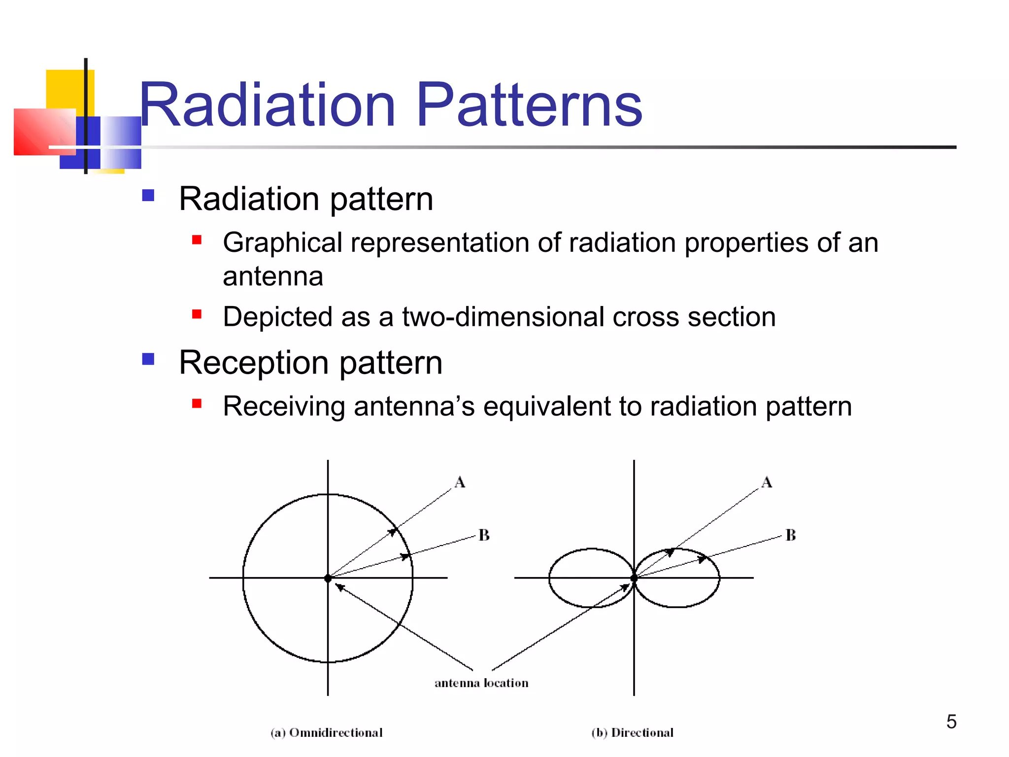
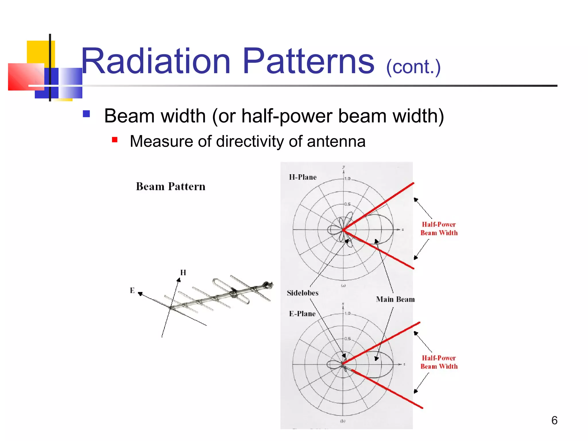
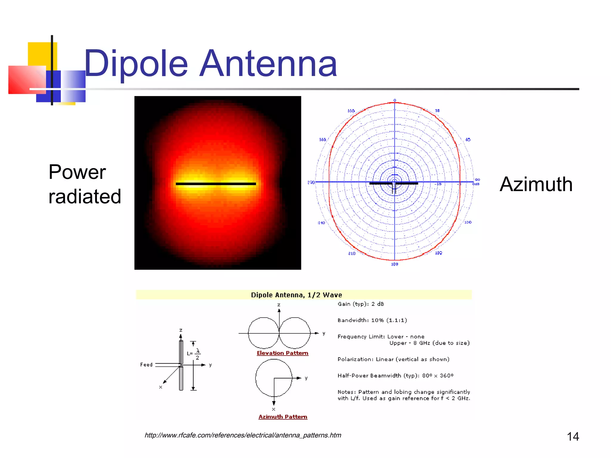
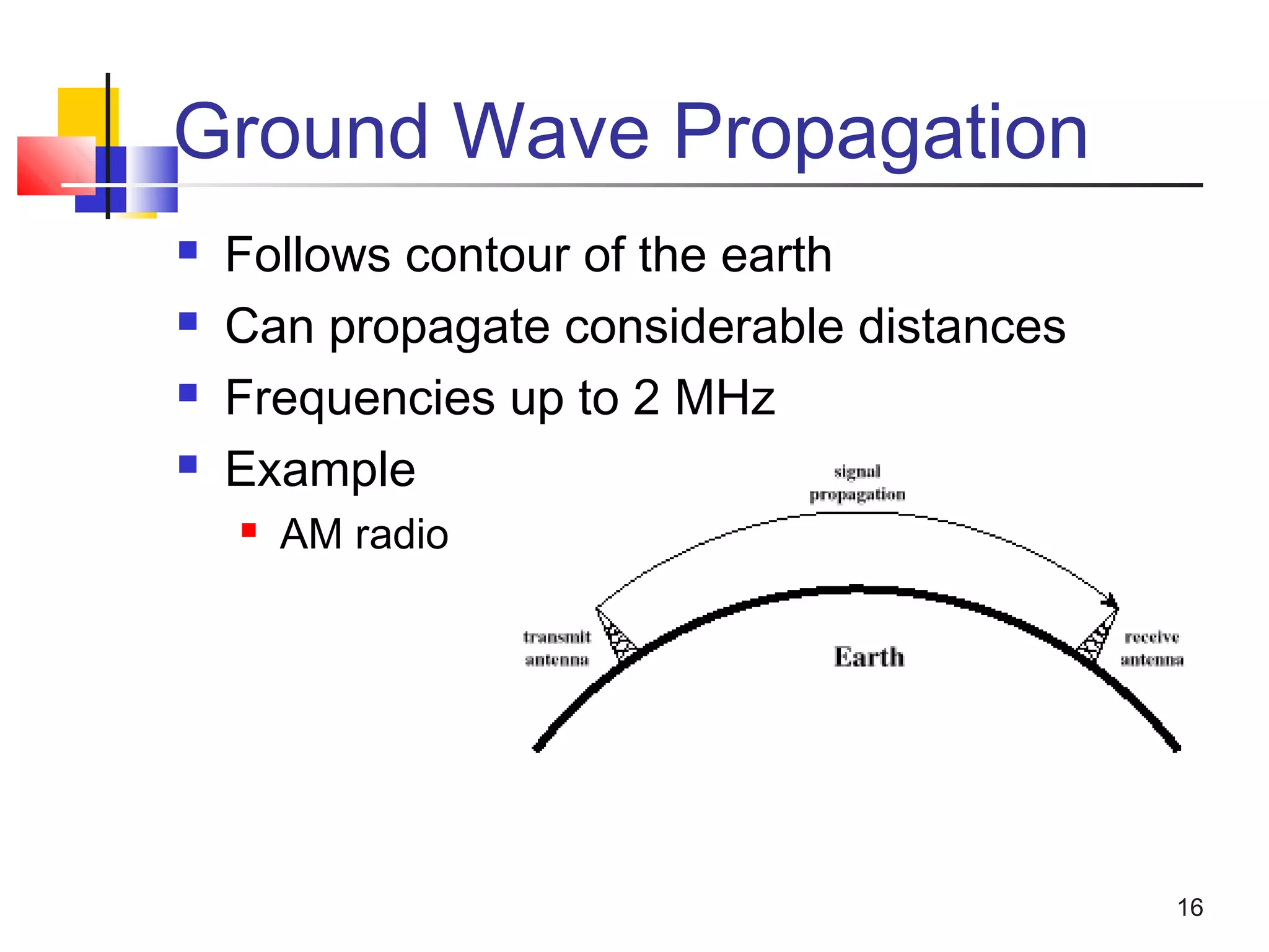
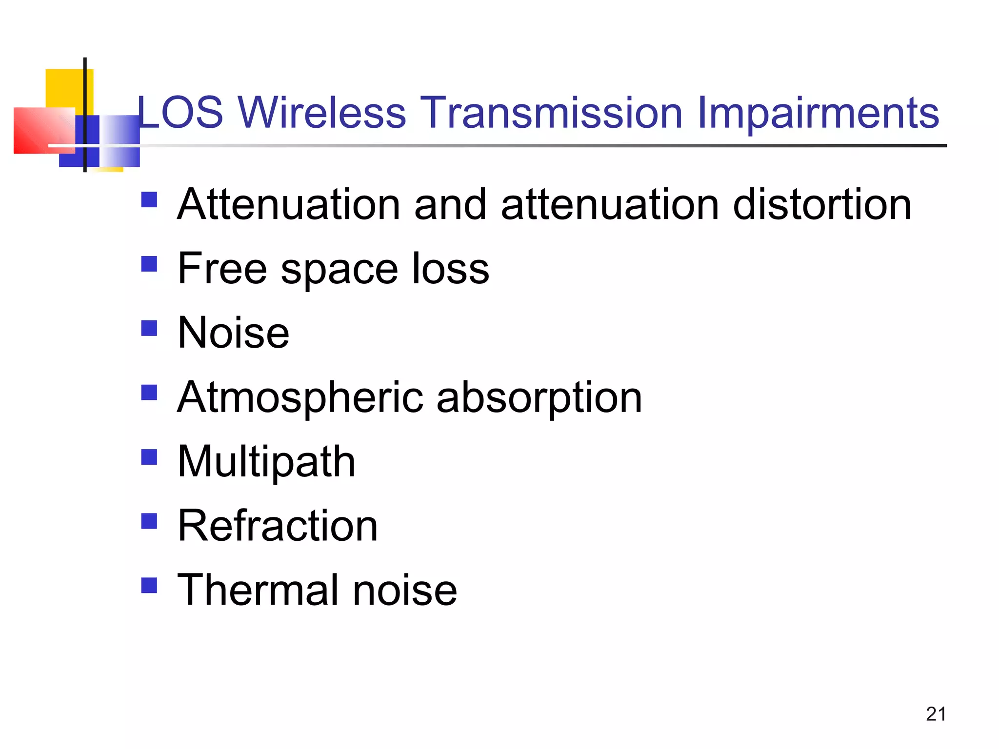
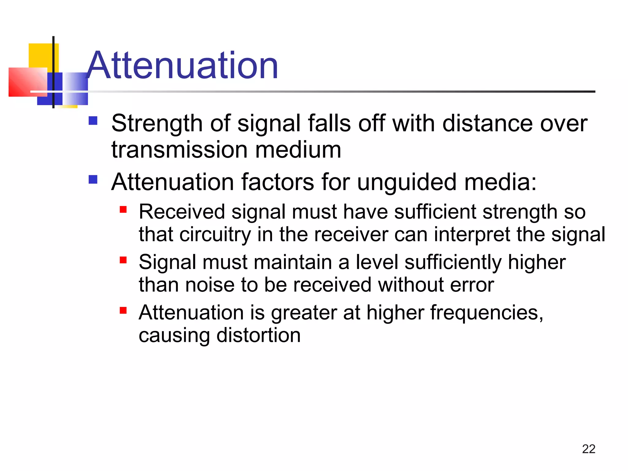
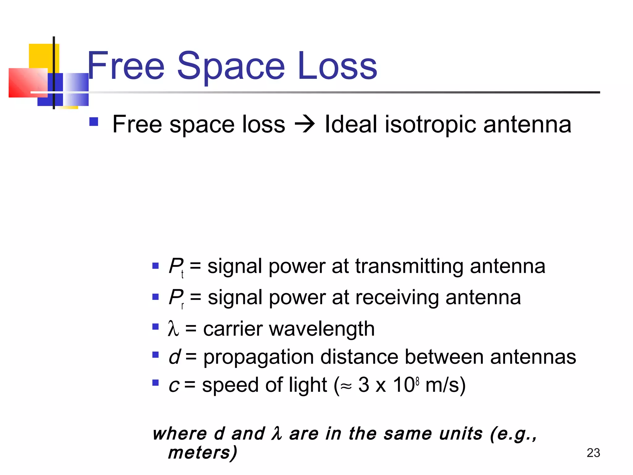
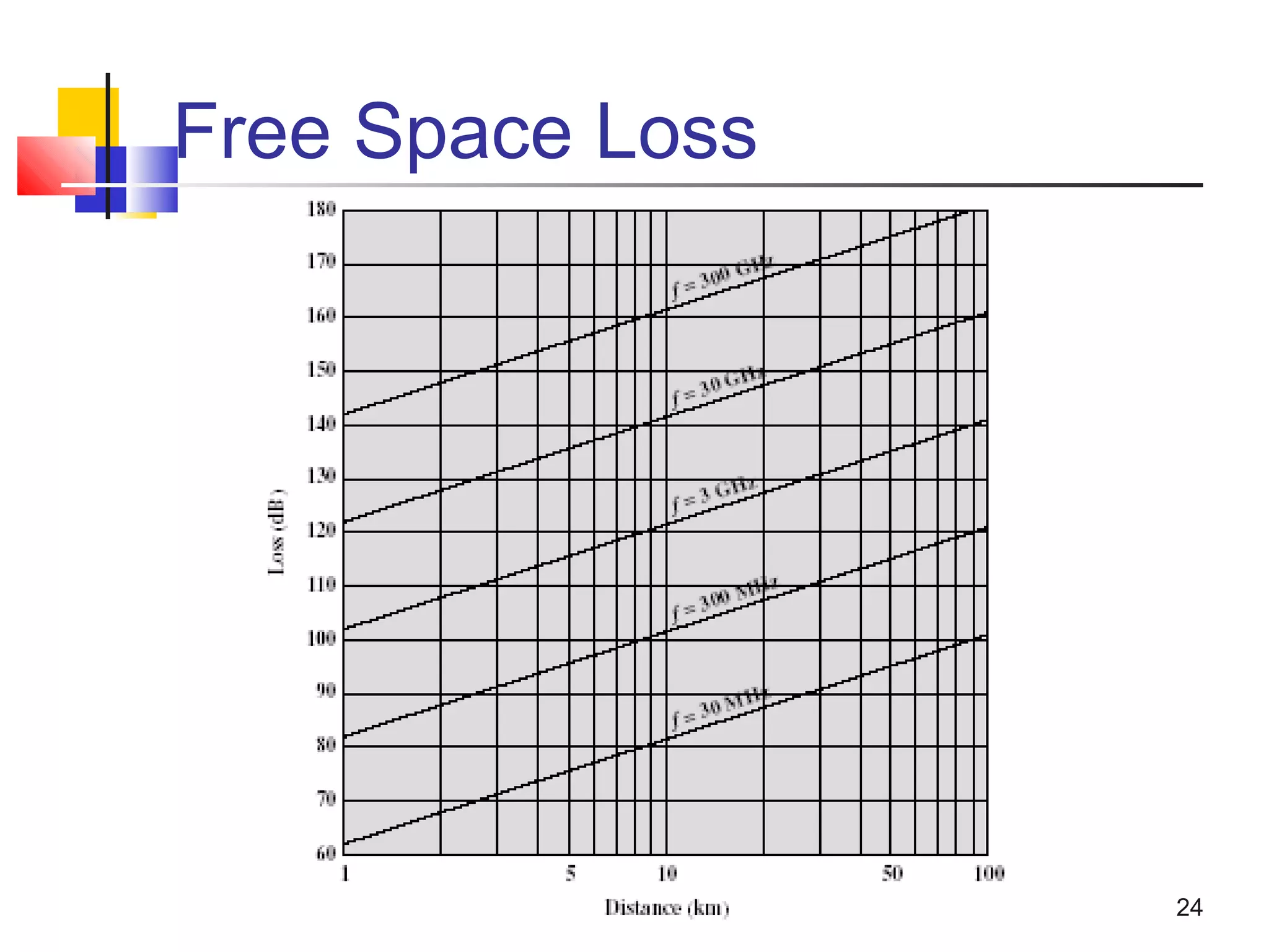
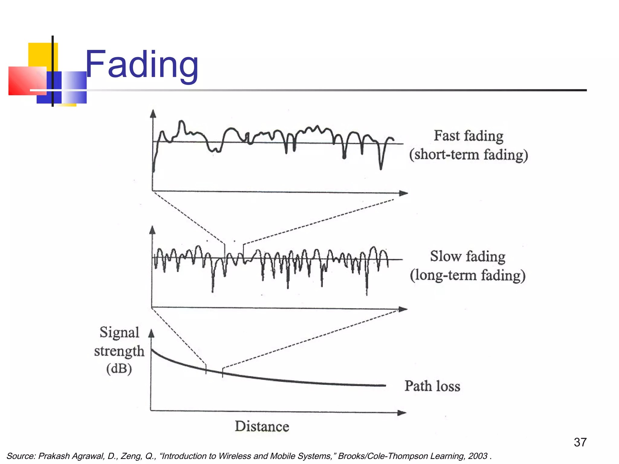

An antenna converts radio frequency electric current into electromagnetic waves that are radiated into space. The same antenna can transmit and receive signals. Key antenna concepts include reciprocity, radiation patterns, gain, and polarization. Antenna gain compares its power output to an isotropic antenna. Common antennas include dipole, parabolic reflective, and types are optimized for propagation modes like ground wave, sky wave, and line-of-sight. Signal strength is reduced by factors like free space loss, noise, multipath, and fading over the transmission path.


![Vibe Coding vs. Spec-Driven Development [Free Meetup]](https://cdn.slidesharecdn.com/ss_thumbnails/vibecodingvsspecdrivendevelopment-251209105622-43f455e7-thumbnail.jpg?width=640&height=640&fit=bounds)


