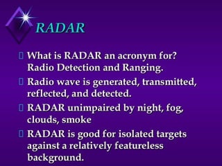
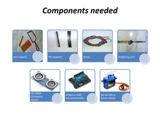
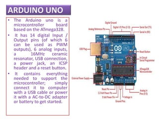
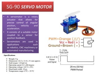
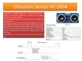
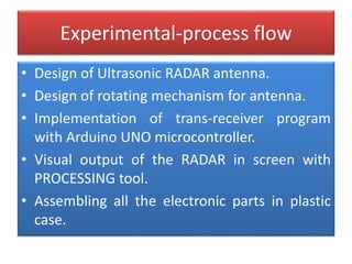
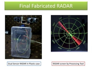
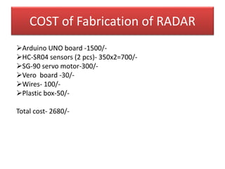
Design and Fabrication of dual
Ultrasound based Pulse Wave
RADAR with 360o vision
By
SANJEEV KUMAR- ECE-4th yr (2016
passout)
A project work submitted for partial fulfillment of
B. Tech in Electronics & Communication
Of
Hooghly Engineering and Technology College
Under the guidance and supervision of
Mr. Swarup Samanta
ACKNOWLEDGEMENT
We would like to thank Sir. Swarup Samanta
for his motivational discussions.
We would also like to thank Mr. Avishek Das, for his
constant help during the fabrication and his tutorials
for programming Arduino and Processing Tool.
Mr. Avishek Das is an attached Ph.D student of
Institute of Materials Research and Engineering
(IMRE), Singapore and Senior research scholar of
Department of Electronic science, University of
Calcutta. He is currently doing research in Nano-
dimentional semiconductor devices.
CONTENTS:-
• DEFINITION OF RADAR
• COMPONENTS NEEDED
• ARDUINO UNO
• SG 90 –SERVO METER
• ULTRASONIC SENSOR HC SR04
• EXPERIMENTAL PROCESS FLOW
• DESIGN OF DUAL ULTRASONIC RADAR
ANTENNA
• APPLICATIONS OF RADAR
• ADVANTAGES OF RADAR
Components needed
Vero board Pin headers Wires Soldering iron
HC-SR04
Ultrasonic
sensor
Arduino UNO
microcontroller
SG-90 Micro-
Servo motor
ARDUINO UNO
• The Arduino uno is a
microcontroller board
based on the ATmega328.
• It has 14 digital Input /
Output pins (of which 6
can be used as PWM
outputs), 6 analog inputs,
a 16MHz ceramic
resonator, USB connection,
a power jack, an ICSP
header and a reset button.
• It contains everything
needed to support the
microcontroller; simply
connect it to computer
with a USB cable or power
it with a AC-to-DC adapter
or battery to get started.
SG-90 SERVO MOTOR
• A servomotor is a rotary
actuator that allows for
precise control of angular
position, velocity and
acceleration.
• It consists of a suitable motor
coupled to a sensor for
position feedback.
• Servomotors are used in
applications such
as robotics, CNC machinery or
automated manufacturing.
Ultrasonic Sensor HC-SR04
 Ultrasonic ranging module HC - SR04 provides 2cm -
400cm non-contact measurement function, the ranging
accuracy can reach to 3mm.
 The modules includes ultrasonic transmitters, receiver and
control circuit.
 The basic principle of work: (1) Using IO trigger for at least
10us high level signal, (2) The Module automatically sends
eight 40 kHz and detect whether there is a pulse signal back.
(3) IF the signal back, through high level , time of high
output IO duration is the time from sending ultrasonic to
returning.
 Test distance = (high level time×velocity of sound (340m/S)
/ 2.
Experimental-process flow
• Design of Ultrasonic RADAR antenna.
• Design of rotating mechanism for antenna.
• Implementation of trans-receiver program
with Arduino UNO microcontroller.
• Visual output of the RADAR in screen with
PROCESSING tool.
• Assembling all the electronic parts in plastic
case.
Design of dual Ultrasonic RADAR antenna & Design of rotating mechanism for
antenna
1. At first Vero board is
cut in small segment.
2. Socket pins are
soldered to the
board.
3. Multiple wires were
soldered accordingly
for two different
sensors in such a
manner to minimize
the no. of wires.
4. Finally, two sensors
were plugged to the
corresponding
sockets and the
board was mounted
on the SG-90 servo
motor.
Circuit diagram of DUAL RADAR sensor
to Arduino
Programming Arduino UNO
1. Arduino Uno micro controller board
was connected with Pc or Laptop via
standard USB cable.
2. The program codes were written in C
compiler based Arduino IDE.
3. Sensor and motor’s Input and
output were assigned into the
program In the following manner:-
#include <Servo.h>.
#define PWR 13
#define GND 8
#define trigPin2 9 // for ECO 1
#define echoPin2 10 // for ECO 1
#define trigPin1 11 // for ECO 1
#define echoPin1 12 // for ECO 1
Servo myServo;
void setup() {
Serial.begin (9600);
myServo.attach(6);
pinMode(trigPin1, OUTPUT);
pinMode(echoPin1, INPUT);
pinMode(trigPin2, OUTPUT);
pinMode(echoPin2, INPUT);
pinMode(PWR, OUTPUT);
pinMode(GND, OUTPUT);
digitalWrite(PWR, HIGH);
digitalWrite(GND, LOW);
}
Programming Processing Tool for RADAR screen Visual
1. Serial output data of Arduino
contains Present status of
rotation angle and measured
distance by two sensors in
centimeter.
2. These three serial output
parameters were transferred
to PROCESSING environment
Software.
3. With the help of java script
coding a visual interface was
developed and using the
serial o/p parameters from
Arduino, real time
visualization of the dual
RADAR was developed.
Final Fabricated RADAR
Dual Sensor RADAR in Plastic case RADAR screen by Processing Tool
COST of Fabrication of RADAR
Arduino UNO board -1500/-
HC-SR04 sensors (2 pcs)- 350x2=700/-
SG-90 servo motor-300/-
Vero board -30/-
Wires- 100/-
Plastic box-50/-
Total cost- 2680/-
RADAR
RADAR
RADAR
RADAR
RADAR
RADAR
RADAR
RADAR
RADAR

RADAR

  • 1.
    Design and Fabricationof dual Ultrasound based Pulse Wave RADAR with 360o vision By SANJEEV KUMAR- ECE-4th yr (2016 passout) A project work submitted for partial fulfillment of B. Tech in Electronics & Communication Of Hooghly Engineering and Technology College Under the guidance and supervision of Mr. Swarup Samanta
  • 2.
    ACKNOWLEDGEMENT We would liketo thank Sir. Swarup Samanta for his motivational discussions. We would also like to thank Mr. Avishek Das, for his constant help during the fabrication and his tutorials for programming Arduino and Processing Tool. Mr. Avishek Das is an attached Ph.D student of Institute of Materials Research and Engineering (IMRE), Singapore and Senior research scholar of Department of Electronic science, University of Calcutta. He is currently doing research in Nano- dimentional semiconductor devices.
  • 3.
    CONTENTS:- • DEFINITION OFRADAR • COMPONENTS NEEDED • ARDUINO UNO • SG 90 –SERVO METER • ULTRASONIC SENSOR HC SR04 • EXPERIMENTAL PROCESS FLOW • DESIGN OF DUAL ULTRASONIC RADAR ANTENNA • APPLICATIONS OF RADAR • ADVANTAGES OF RADAR
  • 5.
    Components needed Vero boardPin headers Wires Soldering iron HC-SR04 Ultrasonic sensor Arduino UNO microcontroller SG-90 Micro- Servo motor
  • 6.
    ARDUINO UNO • TheArduino uno is a microcontroller board based on the ATmega328. • It has 14 digital Input / Output pins (of which 6 can be used as PWM outputs), 6 analog inputs, a 16MHz ceramic resonator, USB connection, a power jack, an ICSP header and a reset button. • It contains everything needed to support the microcontroller; simply connect it to computer with a USB cable or power it with a AC-to-DC adapter or battery to get started.
  • 7.
    SG-90 SERVO MOTOR •A servomotor is a rotary actuator that allows for precise control of angular position, velocity and acceleration. • It consists of a suitable motor coupled to a sensor for position feedback. • Servomotors are used in applications such as robotics, CNC machinery or automated manufacturing.
  • 8.
    Ultrasonic Sensor HC-SR04 Ultrasonic ranging module HC - SR04 provides 2cm - 400cm non-contact measurement function, the ranging accuracy can reach to 3mm.  The modules includes ultrasonic transmitters, receiver and control circuit.  The basic principle of work: (1) Using IO trigger for at least 10us high level signal, (2) The Module automatically sends eight 40 kHz and detect whether there is a pulse signal back. (3) IF the signal back, through high level , time of high output IO duration is the time from sending ultrasonic to returning.  Test distance = (high level time×velocity of sound (340m/S) / 2.
  • 9.
    Experimental-process flow • Designof Ultrasonic RADAR antenna. • Design of rotating mechanism for antenna. • Implementation of trans-receiver program with Arduino UNO microcontroller. • Visual output of the RADAR in screen with PROCESSING tool. • Assembling all the electronic parts in plastic case.
  • 10.
    Design of dualUltrasonic RADAR antenna & Design of rotating mechanism for antenna 1. At first Vero board is cut in small segment. 2. Socket pins are soldered to the board. 3. Multiple wires were soldered accordingly for two different sensors in such a manner to minimize the no. of wires. 4. Finally, two sensors were plugged to the corresponding sockets and the board was mounted on the SG-90 servo motor.
  • 11.
    Circuit diagram ofDUAL RADAR sensor to Arduino
  • 12.
    Programming Arduino UNO 1.Arduino Uno micro controller board was connected with Pc or Laptop via standard USB cable. 2. The program codes were written in C compiler based Arduino IDE. 3. Sensor and motor’s Input and output were assigned into the program In the following manner:- #include <Servo.h>. #define PWR 13 #define GND 8 #define trigPin2 9 // for ECO 1 #define echoPin2 10 // for ECO 1 #define trigPin1 11 // for ECO 1 #define echoPin1 12 // for ECO 1 Servo myServo; void setup() { Serial.begin (9600); myServo.attach(6); pinMode(trigPin1, OUTPUT); pinMode(echoPin1, INPUT); pinMode(trigPin2, OUTPUT); pinMode(echoPin2, INPUT); pinMode(PWR, OUTPUT); pinMode(GND, OUTPUT); digitalWrite(PWR, HIGH); digitalWrite(GND, LOW); }
  • 13.
    Programming Processing Toolfor RADAR screen Visual 1. Serial output data of Arduino contains Present status of rotation angle and measured distance by two sensors in centimeter. 2. These three serial output parameters were transferred to PROCESSING environment Software. 3. With the help of java script coding a visual interface was developed and using the serial o/p parameters from Arduino, real time visualization of the dual RADAR was developed.
  • 14.
    Final Fabricated RADAR DualSensor RADAR in Plastic case RADAR screen by Processing Tool
  • 15.
    COST of Fabricationof RADAR Arduino UNO board -1500/- HC-SR04 sensors (2 pcs)- 350x2=700/- SG-90 servo motor-300/- Vero board -30/- Wires- 100/- Plastic box-50/- Total cost- 2680/-