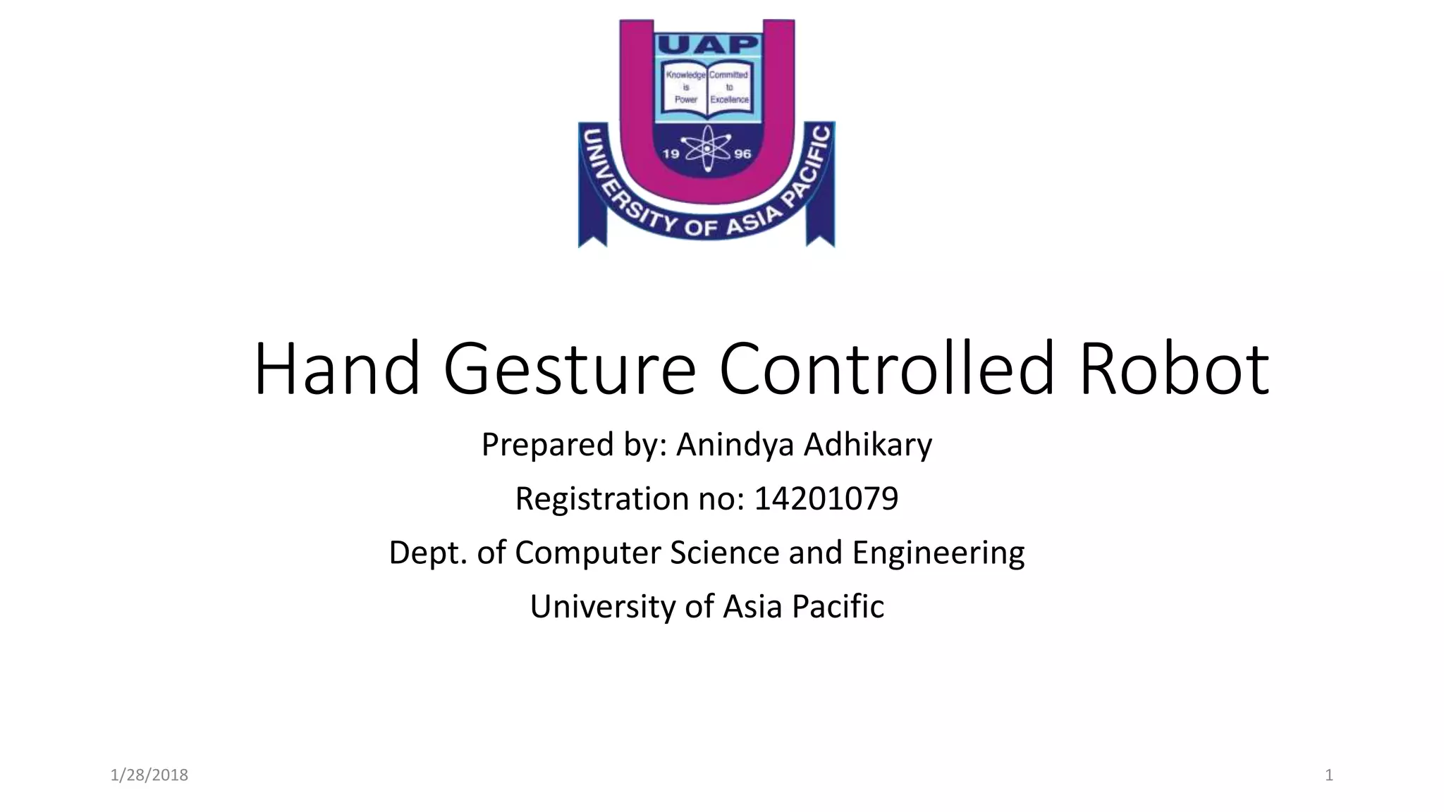
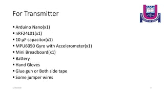
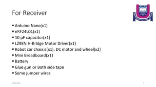
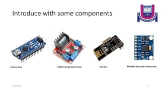
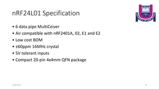
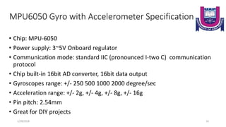
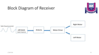
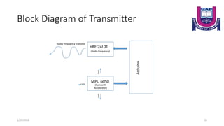
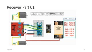
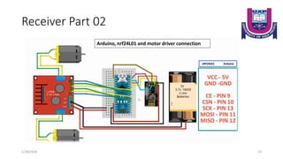
Hand Gesture Controlled Robot
Prepared by: Anindya Adhikary
Registration no: 14201079
Dept. of Computer Science and Engineering
University of Asia Pacific
1/28/2018 1
1/28/2018 2
Introduction
The decision of making a gesture controlled robot that will be operated
by a hand gloved mounted with the transmission circuit assembly. The
circuit assembly will consist of MPU-6050 Gyro Accelerometer sensor
for direction control & Arduino board along with a nRF24L01 RF
module to establish remote communication (data transfer) which
together function as a input device to the bot.
1/28/2018 3
AIM
Where human intervention is not possible or is not desirable(e.g.
2013 Savar building collapse), as in the case of spying(e.g. July 2016
Dhaka attack ), so at those places we can use service bots and control
the movement.
85% of people with disability are found in developing countries and
about 10% of Bangladeshi population are affected, here service bots
become handy.
We can use it in Warfield for bomb detection, enemy search, etc.
1/28/2018 4
Components
1/28/2018 5
For Transmitter
 Arduino Nano(x1)
 nRF24L01(x1)
 10 μF capacitor(x1)
 MPU6050 Gyro with Accelerometer(x1)
 Mini Breadboard(x1)
 Battery
 Hand Gloves
 Glue gun or Both side tape
 Some jumper wires
1/28/2018 6
For Receiver
1/28/2018 7
 Arduino Nano(x1)
 nRF24L01(x1)
 10 μF capacitor(x1)
 L298N H-Bridge Motor Driver(x1)
 Robot car chassis(x1), DC motor and wheel(x2)
 Mini Breadboard(x1)
 Battery
 Glue gun or Both side tape
 Some jumper wires
Introduce with some components
1/28/2018 8
Arduino Nano L298N H-Bridge Motor Driver MPU6050 Gyro with AccelerometernRF24L01
Specifications Arduino nano 01
• Microcontroller ATmega328
• Operating Voltage (logic level): 5 V
• Input Voltage (recommended): 7-12 V
• Input Voltage (limits): 6-20 V
• Digital I/O Pins : 14 (of which 6 provide PWM output)
• Analog Input Pins: 8
• DC Current per I/O Pin: 40 mA
• Flash Memory 32 KB (ATmega328) of which 2 KB used by bootloader
• SRAM: 2 KB (ATmega328)
• EEPROM: 1 KB (ATmega328)
• Clock Speed: 16 MHz
• Dimensions: 0.73" x 1.70"
1/28/2018 9
Arduino nano Hardware Design
Powering the Arduino Nano:
The Arduino Nano can be powered via the
Mini-B USB connection, 6-20V unregulated
external power supply (pin 30), or 5V
regulated external power supply (pin 27). The
power source is automatically selected to the
highest voltage source.
1/28/2018 10
L298N H-Bridge Motor Driver Specification
• Driver: L298N
• Driver power supply: +5V~+46V
• Driver Io: 2A
• Logic power output Vss: +5~+7V (internal supply +5V)
• Logic current: 0~36mA
• Controlling level: Low -0.3V~1.5V, high: 2.3V~Vss
• Enable signal level: Low -0.3V~1.5V, high: 2.3V~Vss
• Max power: 25W (Temperature 75 celsius)
• Working temperature: -25C~+130C
• Dimension: 60mm*54mm
• Driver weight: ~48g
• Other extensions: current probe, controlling direction indicator, pull-up resistor switch, logic part
power supply.
1/28/2018 11
L298N H-Bridge Motor Driver Hardware Design
1/28/2018 12
nRF24L01 Specification
• Worldwide 2.4GHz ISM band operation
• Up to 2Mbps on air data rate
• Ultra low power operation
• 11.3mA TX at 0dBm output power
• 12.3mA RX at 2Mbps air data rate
• 900nA in power down
• 22µA in standby-I
• On chip voltage regulator
• 1.9 to 3.6V supply range
• Enhanced ShockBurst™
• Automatic packet handling
• Auto packet transaction handling
1/28/2018 13
nRF24L01 Specification
• 6 data pipe MultiCeiver
• Air compatible with nRF2401A, 02, E1 and E2
• Low cost BOM
• ±60ppm 16MHz crystal
• 5V tolerant inputs
• Compact 20-pin 4x4mm QFN package
1/28/2018 14
Hardware Design
1/28/2018 15
Front Side
Back Side
MPU6050 Gyro with Accelerometer Specification
• Chip: MPU-6050
• Power supply: 3~5V Onboard regulator
• Communication mode: standard IIC (pronounced I-two C) communication
protocol
• Chip built-in 16bit AD converter, 16bit data output
• Gyroscopes range: +/- 250 500 1000 2000 degree/sec
• Acceleration range: +/- 2g, +/- 4g, +/- 8g, +/- 16g
• Pin pitch: 2.54mm
• Great for DIY projects
1/28/2018 16
Hardware Design
1/28/2018 17
Front side Back side
Block Diagram
1/28/2018 18
Block Diagram of Receiver
1/28/2018 19
nRF24L01 Arduino Motor Driver
Left Motor
Right Motor
Radio frequency received
(Radio Frequency)
Block Diagram of Transmitter
1/28/2018 20
nRFf24L01
Arduino
Radio frequency transmit
MPU 6050
(Gyro with
Accelerator)
(Radio Frequency)
x-axis
y-axisz-axis
Circuit Diagram
1/28/2018 21
Receiver Part 01
1/28/2018 22
Arduino and motor driver L298N connection
L298N Arduino nano
Receiver Part 02
1/28/2018 23
nRF24L01 Arduino
Arduino, nrf24L01 and motor driver connection
Transmitter Part 01
1/28/2018 24
MPU6050 Arduino
Arduino and MPU6050 connection
Transmitter Part 02
1/28/2018 25
nRF24L01 Arduino
Arduino, nrf24L01 and MPU6050 connection
Application
 Gestures can be used to control interactions for entertainment
purposes such as gaming to make the game player's experience more
interactive or immersive.
 Through the use of gesture recognition remote control with the wave
of a hand of various devices is possible.
 Industrial application for trolley control, lift control, etc.
 Military application to control robotics.
 Medical application for surgery purpose.
 Construction application.
1/28/2018 26
1/28/2018 27

Hand gesture controlled robot with arduino

  • 1.
    Hand Gesture ControlledRobot Prepared by: Anindya Adhikary Registration no: 14201079 Dept. of Computer Science and Engineering University of Asia Pacific 1/28/2018 1
  • 2.
  • 3.
    Introduction The decision ofmaking a gesture controlled robot that will be operated by a hand gloved mounted with the transmission circuit assembly. The circuit assembly will consist of MPU-6050 Gyro Accelerometer sensor for direction control & Arduino board along with a nRF24L01 RF module to establish remote communication (data transfer) which together function as a input device to the bot. 1/28/2018 3
  • 4.
    AIM Where human interventionis not possible or is not desirable(e.g. 2013 Savar building collapse), as in the case of spying(e.g. July 2016 Dhaka attack ), so at those places we can use service bots and control the movement. 85% of people with disability are found in developing countries and about 10% of Bangladeshi population are affected, here service bots become handy. We can use it in Warfield for bomb detection, enemy search, etc. 1/28/2018 4
  • 5.
  • 6.
    For Transmitter  ArduinoNano(x1)  nRF24L01(x1)  10 μF capacitor(x1)  MPU6050 Gyro with Accelerometer(x1)  Mini Breadboard(x1)  Battery  Hand Gloves  Glue gun or Both side tape  Some jumper wires 1/28/2018 6
  • 7.
    For Receiver 1/28/2018 7 Arduino Nano(x1)  nRF24L01(x1)  10 μF capacitor(x1)  L298N H-Bridge Motor Driver(x1)  Robot car chassis(x1), DC motor and wheel(x2)  Mini Breadboard(x1)  Battery  Glue gun or Both side tape  Some jumper wires
  • 8.
    Introduce with somecomponents 1/28/2018 8 Arduino Nano L298N H-Bridge Motor Driver MPU6050 Gyro with AccelerometernRF24L01
  • 9.
    Specifications Arduino nano01 • Microcontroller ATmega328 • Operating Voltage (logic level): 5 V • Input Voltage (recommended): 7-12 V • Input Voltage (limits): 6-20 V • Digital I/O Pins : 14 (of which 6 provide PWM output) • Analog Input Pins: 8 • DC Current per I/O Pin: 40 mA • Flash Memory 32 KB (ATmega328) of which 2 KB used by bootloader • SRAM: 2 KB (ATmega328) • EEPROM: 1 KB (ATmega328) • Clock Speed: 16 MHz • Dimensions: 0.73" x 1.70" 1/28/2018 9
  • 10.
    Arduino nano HardwareDesign Powering the Arduino Nano: The Arduino Nano can be powered via the Mini-B USB connection, 6-20V unregulated external power supply (pin 30), or 5V regulated external power supply (pin 27). The power source is automatically selected to the highest voltage source. 1/28/2018 10
  • 11.
    L298N H-Bridge MotorDriver Specification • Driver: L298N • Driver power supply: +5V~+46V • Driver Io: 2A • Logic power output Vss: +5~+7V (internal supply +5V) • Logic current: 0~36mA • Controlling level: Low -0.3V~1.5V, high: 2.3V~Vss • Enable signal level: Low -0.3V~1.5V, high: 2.3V~Vss • Max power: 25W (Temperature 75 celsius) • Working temperature: -25C~+130C • Dimension: 60mm*54mm • Driver weight: ~48g • Other extensions: current probe, controlling direction indicator, pull-up resistor switch, logic part power supply. 1/28/2018 11
  • 12.
    L298N H-Bridge MotorDriver Hardware Design 1/28/2018 12
  • 13.
    nRF24L01 Specification • Worldwide2.4GHz ISM band operation • Up to 2Mbps on air data rate • Ultra low power operation • 11.3mA TX at 0dBm output power • 12.3mA RX at 2Mbps air data rate • 900nA in power down • 22µA in standby-I • On chip voltage regulator • 1.9 to 3.6V supply range • Enhanced ShockBurst™ • Automatic packet handling • Auto packet transaction handling 1/28/2018 13
  • 14.
    nRF24L01 Specification • 6data pipe MultiCeiver • Air compatible with nRF2401A, 02, E1 and E2 • Low cost BOM • ±60ppm 16MHz crystal • 5V tolerant inputs • Compact 20-pin 4x4mm QFN package 1/28/2018 14
  • 15.
  • 16.
    MPU6050 Gyro withAccelerometer Specification • Chip: MPU-6050 • Power supply: 3~5V Onboard regulator • Communication mode: standard IIC (pronounced I-two C) communication protocol • Chip built-in 16bit AD converter, 16bit data output • Gyroscopes range: +/- 250 500 1000 2000 degree/sec • Acceleration range: +/- 2g, +/- 4g, +/- 8g, +/- 16g • Pin pitch: 2.54mm • Great for DIY projects 1/28/2018 16
  • 17.
  • 18.
  • 19.
    Block Diagram ofReceiver 1/28/2018 19 nRF24L01 Arduino Motor Driver Left Motor Right Motor Radio frequency received (Radio Frequency)
  • 20.
    Block Diagram ofTransmitter 1/28/2018 20 nRFf24L01 Arduino Radio frequency transmit MPU 6050 (Gyro with Accelerator) (Radio Frequency) x-axis y-axisz-axis
  • 21.
  • 22.
    Receiver Part 01 1/28/201822 Arduino and motor driver L298N connection L298N Arduino nano
  • 23.
    Receiver Part 02 1/28/201823 nRF24L01 Arduino Arduino, nrf24L01 and motor driver connection
  • 24.
    Transmitter Part 01 1/28/201824 MPU6050 Arduino Arduino and MPU6050 connection
  • 25.
    Transmitter Part 02 1/28/201825 nRF24L01 Arduino Arduino, nrf24L01 and MPU6050 connection
  • 26.
    Application  Gestures canbe used to control interactions for entertainment purposes such as gaming to make the game player's experience more interactive or immersive.  Through the use of gesture recognition remote control with the wave of a hand of various devices is possible.  Industrial application for trolley control, lift control, etc.  Military application to control robotics.  Medical application for surgery purpose.  Construction application. 1/28/2018 26
  • 27.