Download to read offline

![B. Technical Specifications:
Module Pin Definitions
III. IMPLEMENTAION OF THE HARDWARE COMPONENTS
USING ARDUINO IDE AND PROCESSING IDE
Components Description:
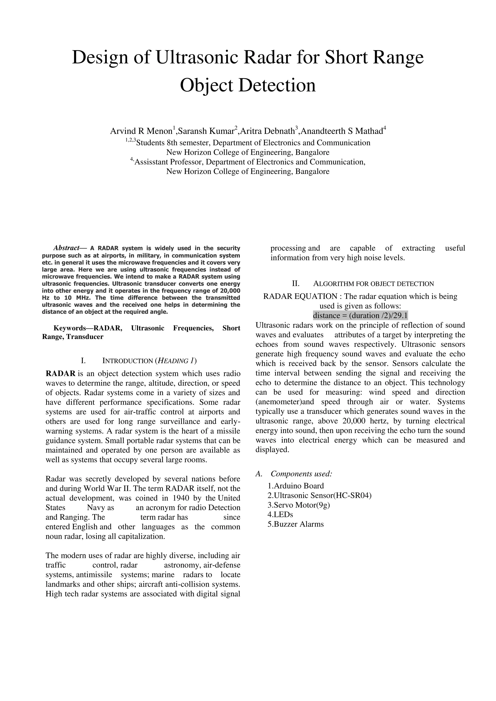
Arduino Uno:
The Uno is a microcontroller board based on the
ATmega328P.It has 14 digital input/output pins (of which
6 can be used as PWM outputs), 6 analog inputs, a 16Mhz
quartz crystal, a USB connection, a power jack, an ICSP
header and a reset button. It contains everything needed to
support the microcontroller by simply connecting it to a
computer with a USB cable or power it with a AC-to-DC
adapter or battery to get started.“UNO” means one in
Italian and was chosen to mark the release of Arduino
Software (IDE).
Ultrasonic Sensor:
Ultrasonic ranging module HC-SR04 provides 2cm-400
cm non-contact measurement function, the ranging
accuracy can reach to 3mm. The modules includes
ultrasonic transmitters, receivers and control circuit.
Servomotor:
A servomotor is a rotary actuator or a linear
actuator that allows for precise control of angular or
linear position, velocity and acceleration. It consists
of a suitable motor coupled to a sensor for position
feedback.It also requires a relatively sophisticated
controller, often a dedicated module designed
specifically for use with servomotors
A. BLOCK DIAGRAM
B. Working
Avoid combining SI and CGS units, such as current in
amperes and magnetic field in oersteds. This often
leads to confusion because equations do not balance
dimensionally. If you must use mixed units, clearly
state the units for each quantity that you use in an
equation.
A servomotor is a rotary actuator or linear
actuator that allows for precise control of angular or
linear position, velocity and acceleration.[1]
It consists
of a suitable motor coupled to a sensor for position
feedback. It also requires a relatively sophisticated
controller, often a dedicated module designed
specifically for use with servomotors. the echoes from
radio or sound waves, respectively.](https://image.slidesharecdn.com/c39e18d0-796a-4def-8075-cd33ba185b8d-161212070706/85/2014_04_msw_a4_format-2-2-320.jpg)
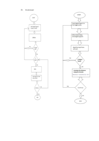
![V. CODE ALGORITHM
1. INCLUDE THE SERVO HEADER FILE.
2. INITIALISE SUITABLE VARIABLE AS PER THE
REQUIREMENT.
3. ATTACH THE SERVO MOTOR TO PIN NUMBER 9 OF
THE ARDUINO BOARD.
4. CONFIGURE PIN NUMBER 6 AND 7 AS INPUT AND
OUTPUT PIN RESPECTIVELY AS REQUIRED BY THE
ULTRASONIC SENSOR.
5. SET THE BAUD RATE AT 9600 HZ
6. START THE MEASUREMENT OF THE DISTANCE BY
KEEPING THE SERVO MOTOR ANGLE AT 0 DEGREE
INITIALLY.
7. THE DISTANCE IS CALCULATED BY DIVIDING THE
TIME REQUIRED BY THE WAVE TO RETURN BACK TO
SENSOR WITH THE SPEED OF SOUND.
8. FOR EACH ANGLE TAKE TEN READINGS AND FIND
OUT THE AVERAGE OF THE TEN READINGS.
9. CHECK IF THE ANGLE IS LESS THAN 180 DEGREE.
10. IF YES INCREMENT THE ANGLE OF THE SERVO
MOTOR BY 1 DEGREE AND GO TO STEP '8'
11. ELSE,
12. DERCREMENT THE ANGLE OF THE SERVO MOTOR
BY 1 DEGREE.
13. FOR EACH ANGLE TAKE TEN READINGS AND FIND
OUT THE AVERAGE OF THE TEN READINGS.
14. CHECK IF THE ANGLE IS GREATER THAN 0 DEGREE.
15. IF YES GO TO STEP 12.
16. ELSE GO TO STEP 6.
Conclusion
This technology comes along with many practical
applications in security and alarm systems for homes, shops
and cars. Radar is based on Microwave and detects the change
in dielectric constant where as Ultrasonic is based on Sound
Wave at high frequency (Ultrasonic Wave) and detects change
in density of medium. For short range detection an ultrasonic
radar is more cost effective. The applications of such have
been seen recently in the self parking car systems launched by
AUDI, FORD etc. And even the upcoming driverless cars by
Google like Prius and Lexus. It has application in the
following fields to name a few:
1. Air Force Applications
2. Naval Applications
3. Military and Army Applications
4. Meteorological Applications
Ultrasonic Radars are used in Vehicles to prevent accidents,
for self parking. New developments in this technology helps
improve the SONAR technology used in submarines and other
underwater vehicles. Ultrasonic technology is being used to
help guide the blind people in use.
References
[1] http://www.arduino.cc/
[2] http://www.arduinoproducts .cc/
[3] http://www.atmel.com/atmega328/
[4] http://www.instructables.com/id/ ATMega328-using-
Arduino-/
[5] http://arduino.cc/en/Tutorial/BarGraph/
[6] http://arduino.cc/en/Tutorial/LiquidCrystal/
[7] http://fritzing.org/](https://image.slidesharecdn.com/c39e18d0-796a-4def-8075-cd33ba185b8d-161212070706/85/2014_04_msw_a4_format-2-4-320.jpg)

The document describes the design of an ultrasonic radar system for short range object detection. It discusses using ultrasonic frequencies instead of microwaves to make a more cost effective radar. The system uses an Arduino board, ultrasonic sensor, servo motor, LEDs and buzzer. It works by sending and receiving ultrasonic pulses and measuring the time delay to determine distance. The servo motor rotates to scan in different angles. Code and algorithms are provided to control the hardware and calculate distance measurements at various angles for object detection.