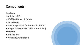
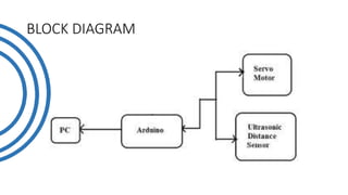
2. Table of Contents
• Introduction to Radar System
• Components and their description
• Block Diagram
• Circuit Diagram
• Working Principle
• Problem Statement
• Key points and improvements
• Applications
• References
3.
4. Introduction
The word radar comes from the acronym radio detection and ranging. As
the name implies, radars use radio waves to determine the distance and
velocity of the targets they hit.
The project is based on Sonar technology as we will be using an Ultrasonic
Sensor to determine the presence of any object in a particular range.
Radar is an object detection system. It uses Microwaves to determine the
range, altitude, direction, or speed of objects. The radar can transmit
radio waves or microwaves which bounce off any object in their path. So,
we can easily determine any object in the radar range.
5. Introduction to Radar System
Radar is a long-range object detection system that uses radio waves to
establish certain parameters of an object like its range, speed and
position
The project is based on Sonar technology as I will be using an
Ultrasonic Sensor to determine the presence of any object in a
particular range.
6. Components:
Hardware
• Arduino UNO
• HC-SR04 Ultrasonic Sensor
• Servo Motor
• Mounting Bracket for Ultrasonic Sensor
• Jumper Cables + USB Cable (for Arduino)
Software
• Arduino IDE
• Processing Application
7. Ultrasonic Sensor:
Ultrasonic sensor is mainly used to determine
the distance of the target object.
Transmitter and receiver are two main parts
of the sensor where former converts an
electrical signal to ultrasonic waves while later
converts that ultrasonic signals back to
electrical signals.
Its operating frequency is 4 MHz and its
detection range is from 2cm to 400 cm.
Servo Motor:
Servo motor is a motor which requires +5V to
operate and having a torque of 2.5kg/cm. It
must be kept in mind that it can only rotate
from 0°-180°.
11. Working Principle
The basic objective of our design is to ascertain the distance position and
speed of the obstacle set at some distance from the sensor. Ultrasonic sensor
sends the ultrasonic wave in various ways by rotating with help of servo
motors. This wave goes in air and gets reflected back subsequent to striking
some object. This wave is again detected by the sensor and its qualities is
analyzed and output is shown in screen indicating parameters, for example,
distance and position of object. Arduino IDE is utilized to compose code and
transfer coding in Arduino and causes us to detect position or angle of servo
motor and it is communicated through the serial port alongside the covered
distance of the nearest object in its way.
Output of all of this working is shown in the software called processing, it
will display the input/output and the range of the object.
12. • Implementations of the sensors are done in such a way that ultra-
sonic sensor is attached on top of the servo motor because it have to
detect the object and its distance. Arduino (micro-controller) will
control the ultra-sonic sensor and servo motor and also powered will
be given to both of them through micro-controller.
• When any obstacle/object is detected by the ultrasonic sensor the
data is immediately processed by the controller and is fed to the IDE
which shows it on the display screen. Here the process ends with an
estimated distance of the object from the system with the angle at
which it is placed.
13. • An HC-SR04 ultrasonic distance sensor actually consists of two
ultrasonic transducers.
• One acts as a transmitter that converts the electrical signal into 40
KHz ultrasonic sound pulses. The other acts as a receiver and listens
for the transmitted pulses.
• When the receiver receives these pulses, it produces an output pulse
whose width is proportional to the distance of the object in front.
• This sensor provides excellent non-contact range detection between 2
cm to 400 cm (~13 feet) with an accuracy of 3 mm.
14. • VCC supplies power to the HC-SR04 ultrasonic sensor. You can
connect it to the 5V output from your Arduino.
• Trig (Trigger) pin is used to trigger ultrasonic sound pulses. By setting
this pin to HIGH for 10µs, the sensor initiates an ultrasonic burst.
• Echo pin goes high when the ultrasonic burst is transmitted and
remains high until the sensor receives an echo, after which it goes
low. By measuring the time the Echo pin stays high, the distance can
be calculated.
15. Problem Statement
When the airplanes were invented so there is need of an instrument
that could detect their location and time. So there is need of a system
that could detect the aircrafts in air.
So to overcome this problem the scientists invented the “Radar
System”, and our whole defense system, air-traffic, airport system is
based on it.
16.
17. Key points and Improvements
• Instead of providing a different voltage source for operating ultrasonic
sensor and servo motor, we have used supply from the micro-
controller. By this way we reduced the cost of voltage supplies.
• Earlier the output screen was like this:
18. • After making some changes in the coding the output screen looks like this:
Now, it will show us the accurate distance as well as angle of the object
which is much more accurate as compared to the previous output. This
output screen is based on the polar coordinates system.
19. Applications
Radar is an electromagnetic system for the detection and location of
target objects such as aircraft, ships, spacecraft, vehicles, people, and
the natural environment which can reflect a signal back.
It uses electromagnetic radio waves to determine the angle, range, or
velocity of objects
The modern radar system is more advanced and the uses of radar are
highly diverse. Such as Air traffic control, Air-defance system, Radar
Astronomy, Antimissile system, Ocean Surveillance system, outer space
surveillance and many more.