


![5.2. Graphs 21
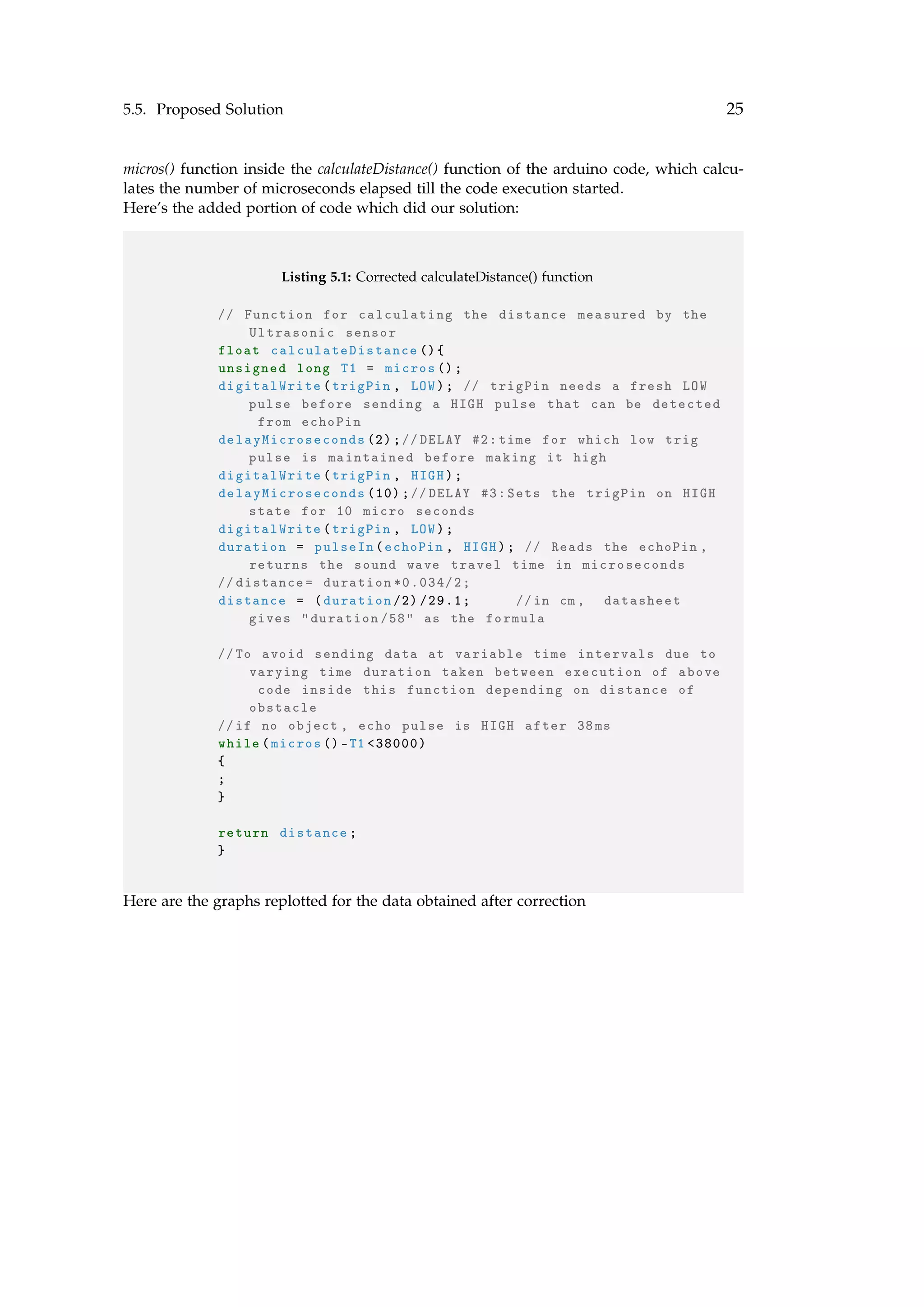
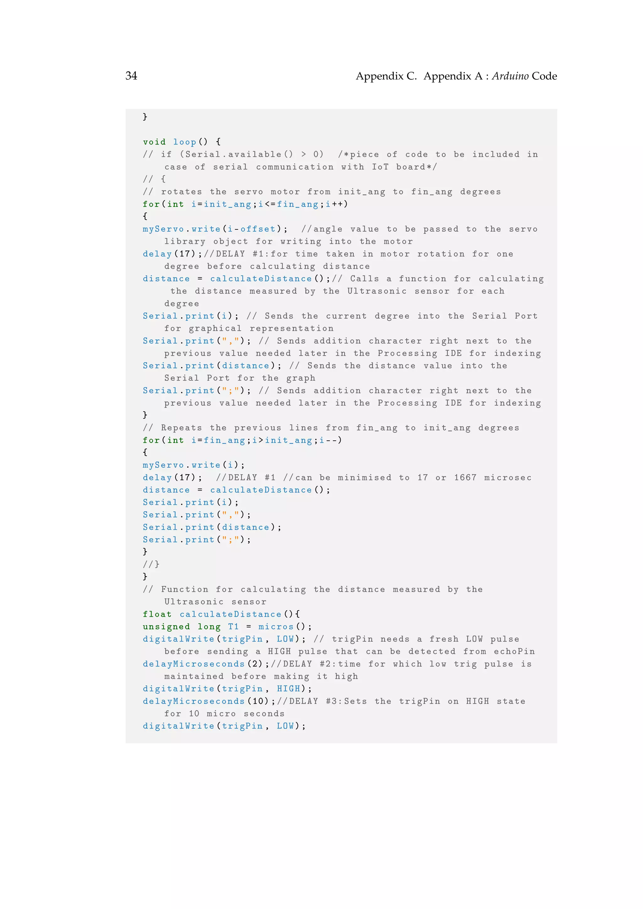
We took into account the several delays introduced in the code, along with the delay in
rotation of the motor(specified by its speed given in its datasheet, tested to be accurate)
and delay in calculation of distance. Accordingly, we minimised each of the values given
as arguments to the
delay()
function used at different parts of the Arduino code, to the safest least value possible. Each
of the delays with descriptions can be observed in the Arduino code given with comments
in Appendix C
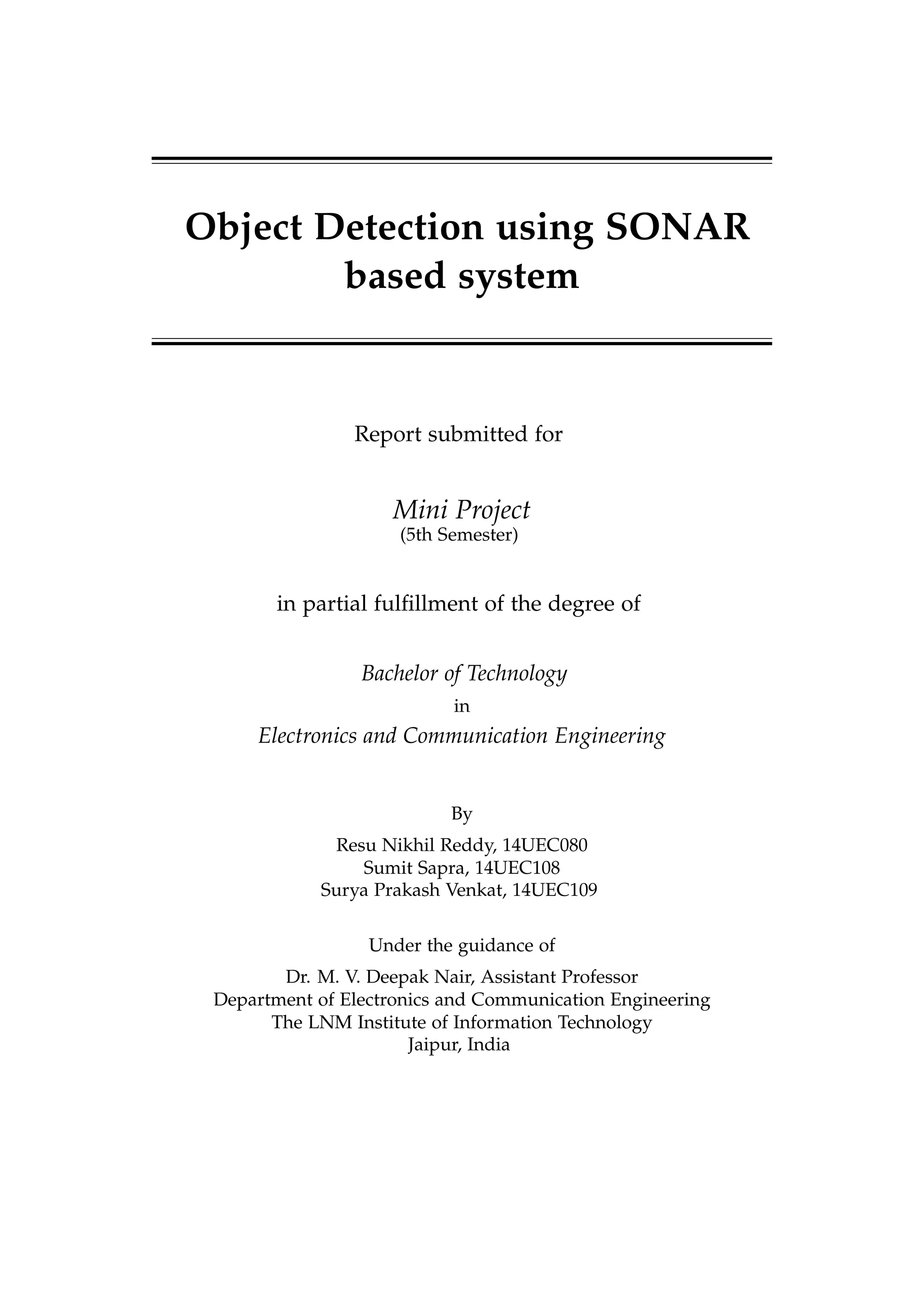
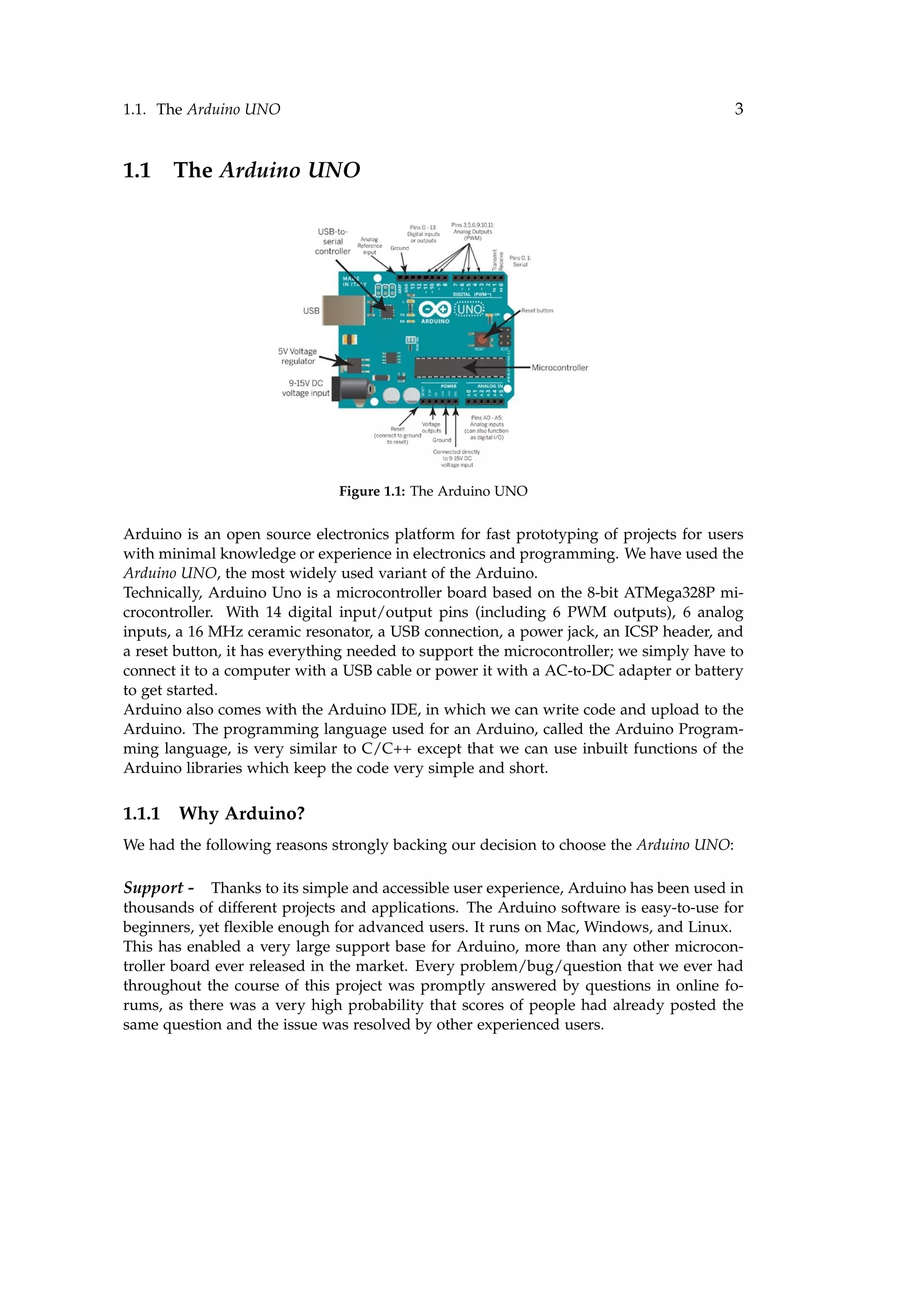
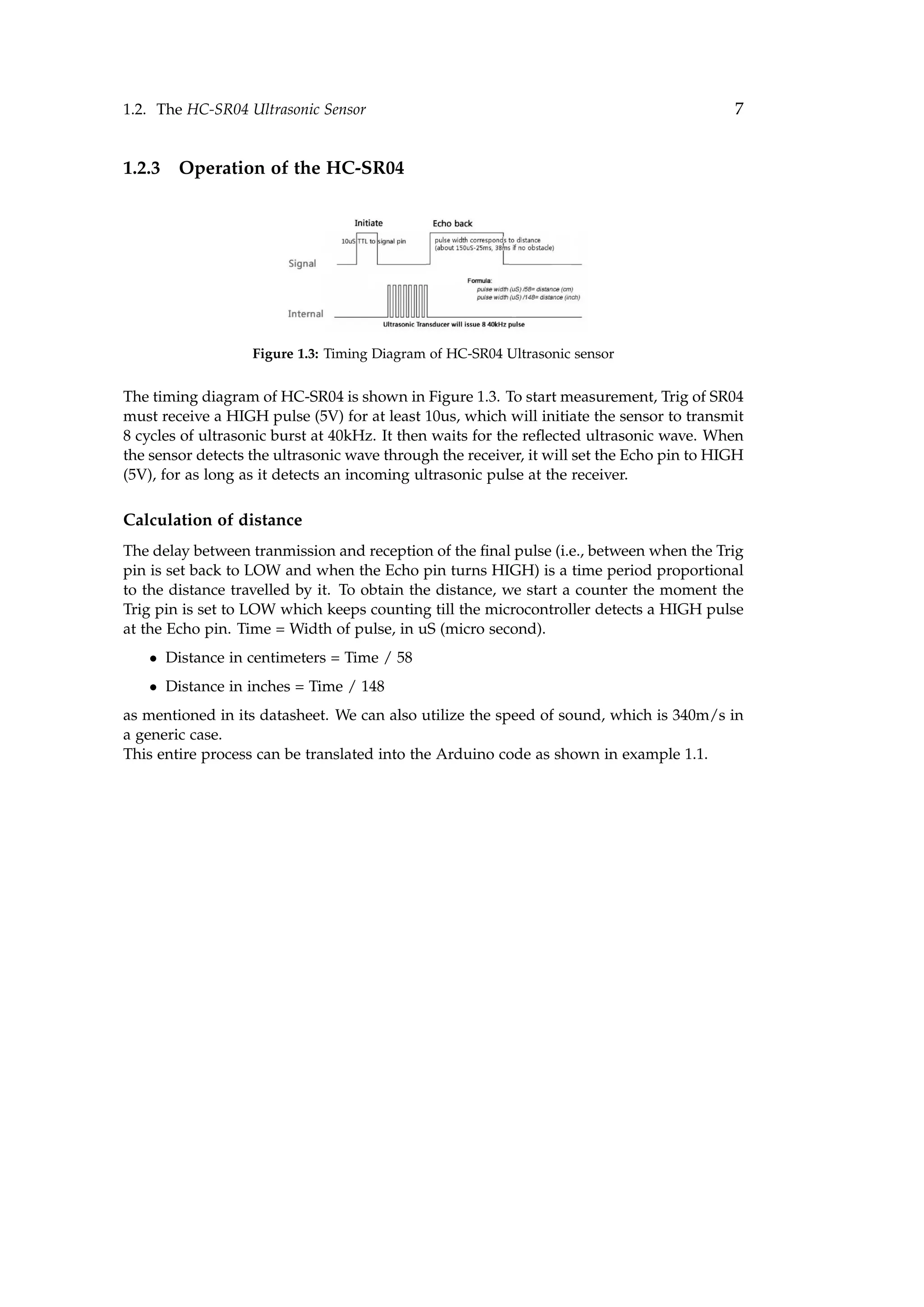
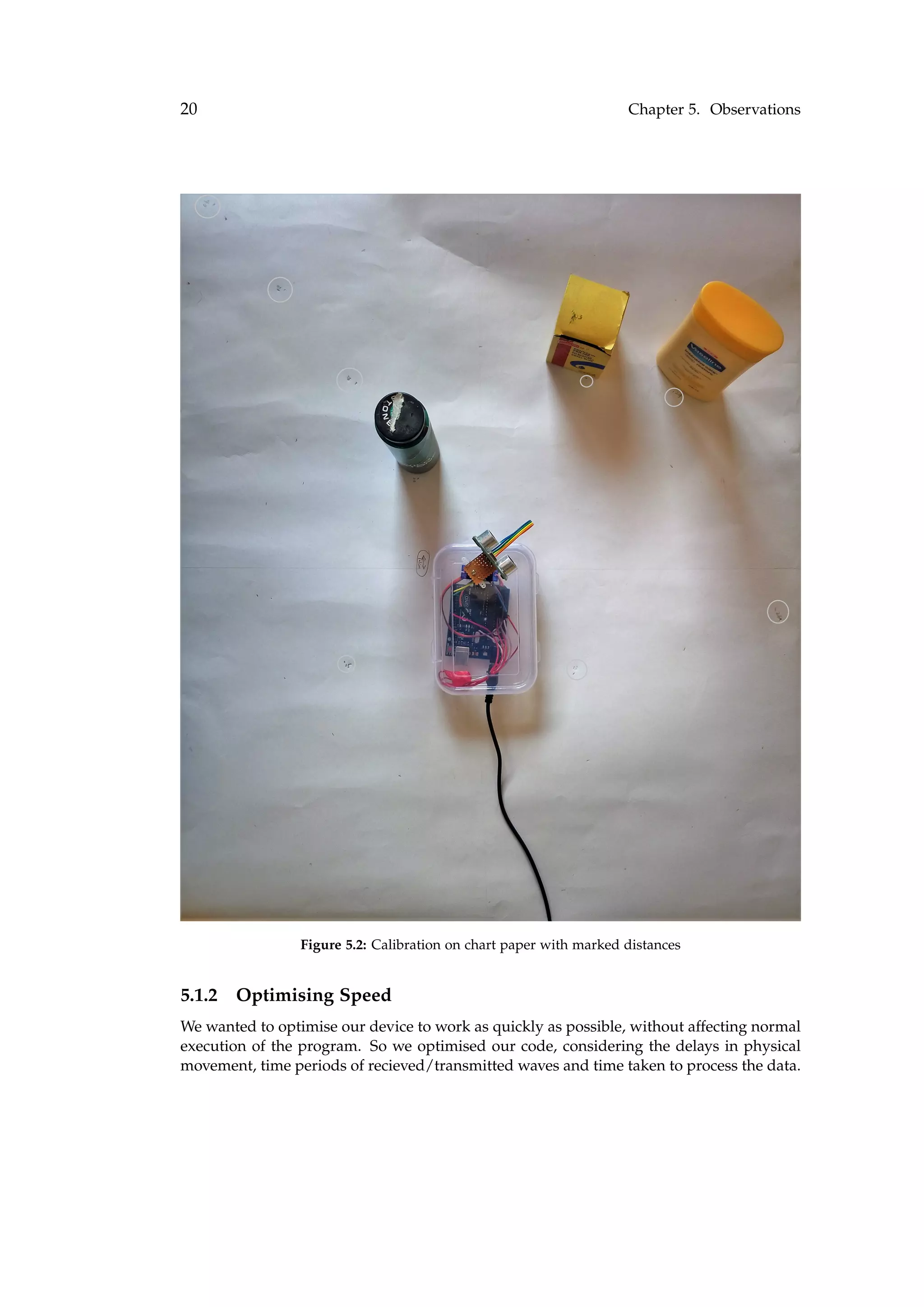
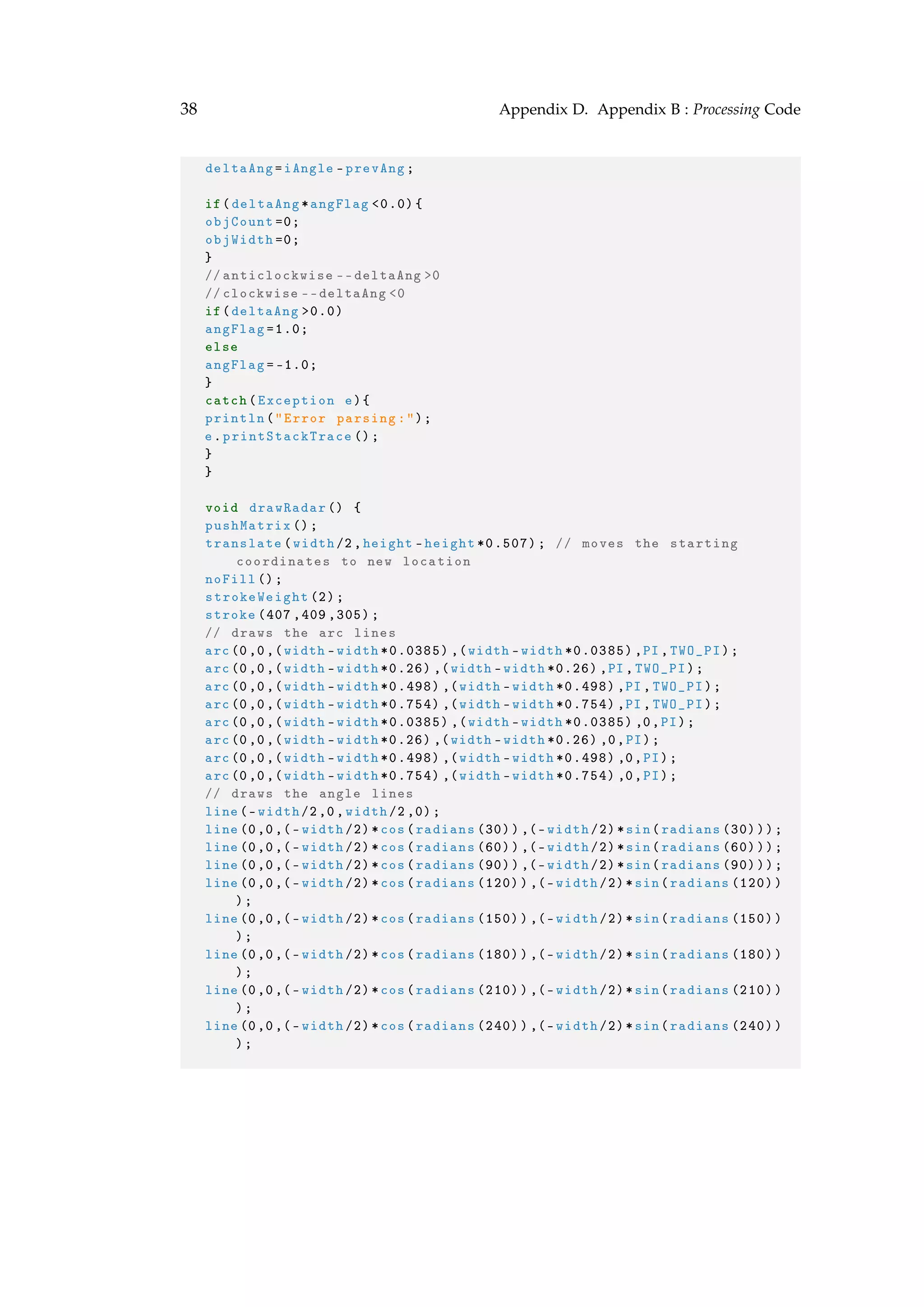
5.2 Graphs
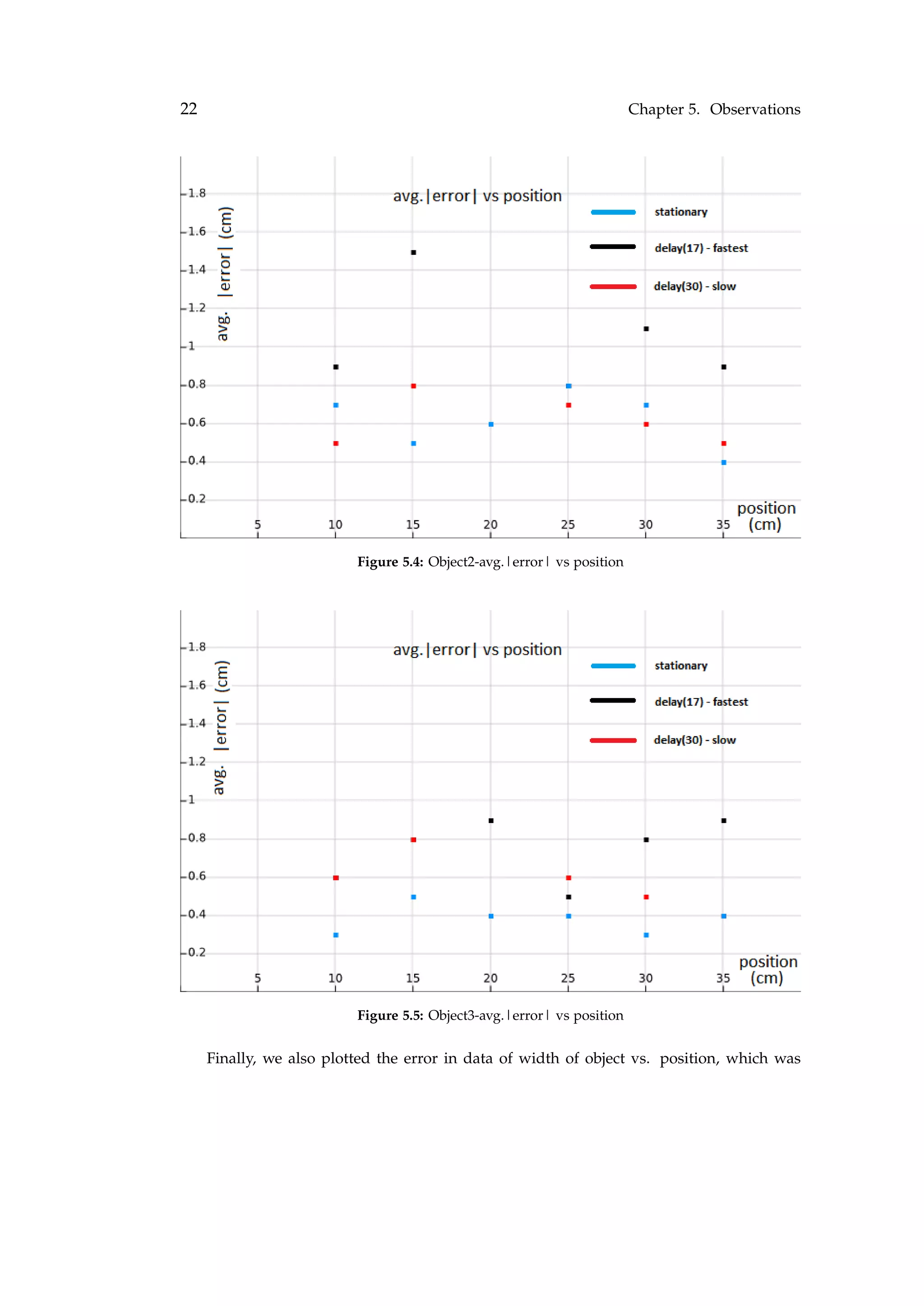
We obtained the following [error vs. position] graphs for three different kinds of objects
kept in front of the sensor. In each case, we noted down values for both the sensor being
stationary, and rotating. The three different kinds of objects were
Object1 = Hollow plastic bottle (width=6cm) Object2 = Solid DC battery (width=3cm) Ob-
ject3 = Metallic pen (width=0.8cm)
Figure 5.3: Object1-avg.|error| vs position](https://image.slidesharecdn.com/sonarprojectreport-170128210420/75/Sonar-Project-Report-26-2048.jpg)


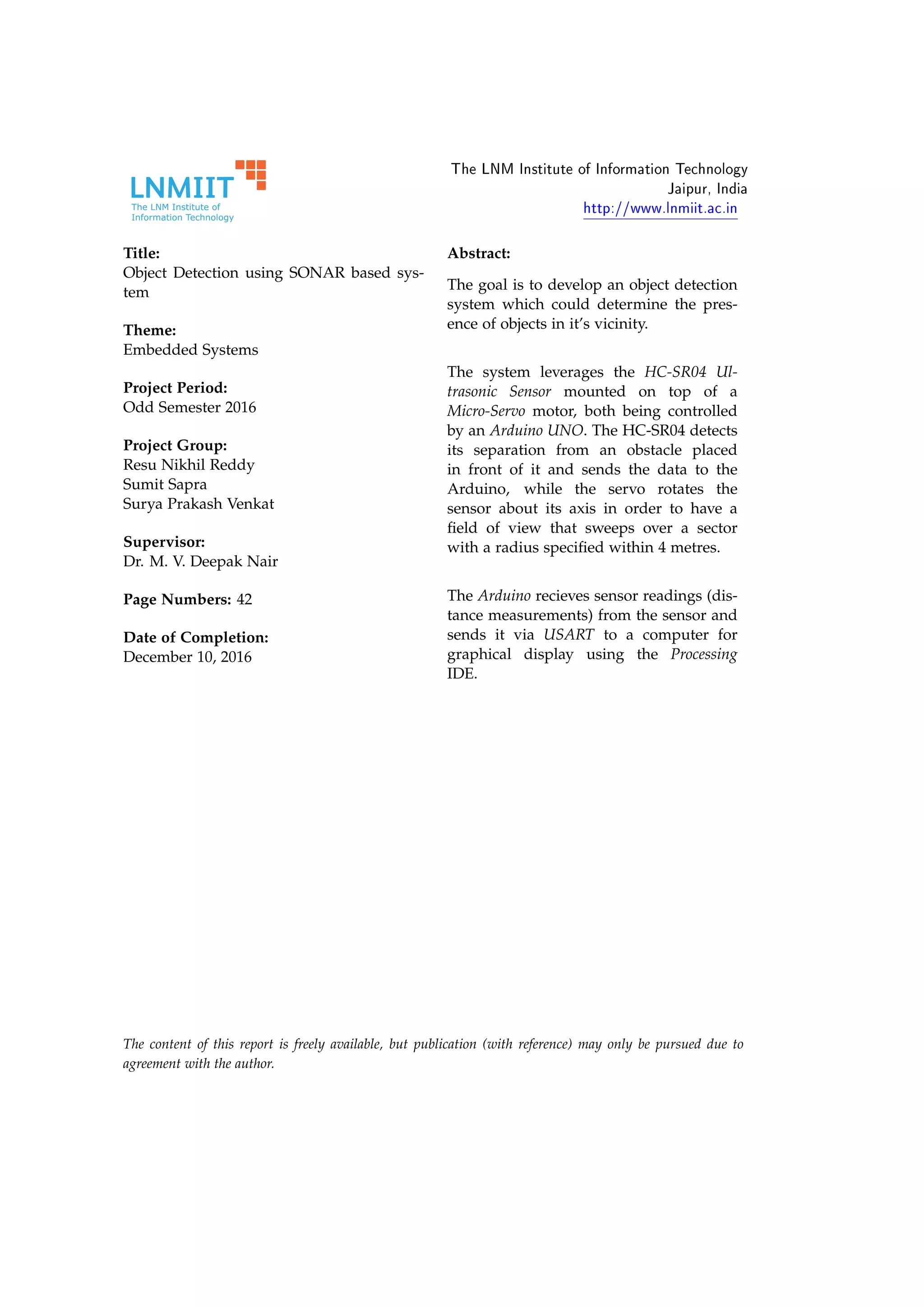
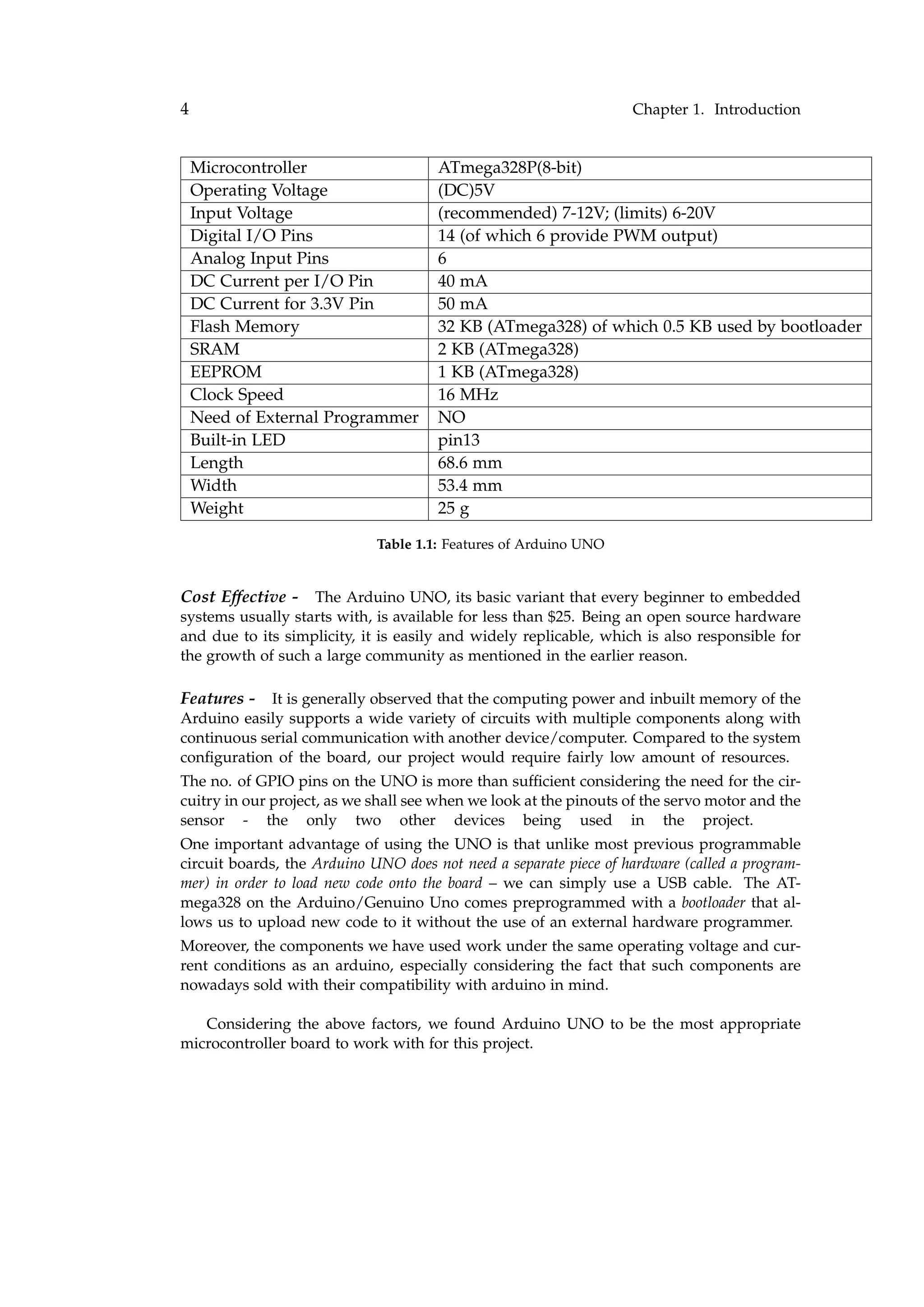
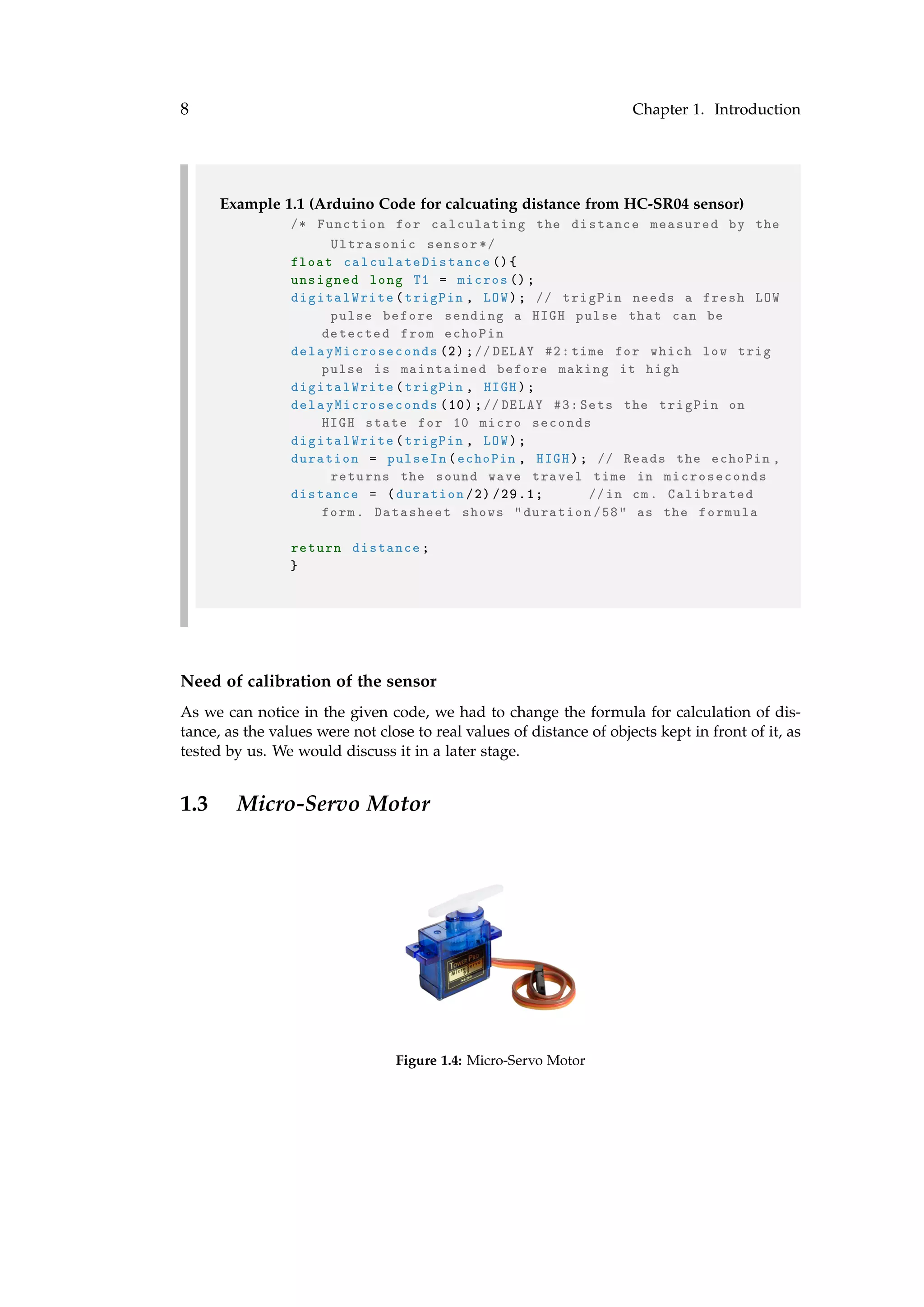
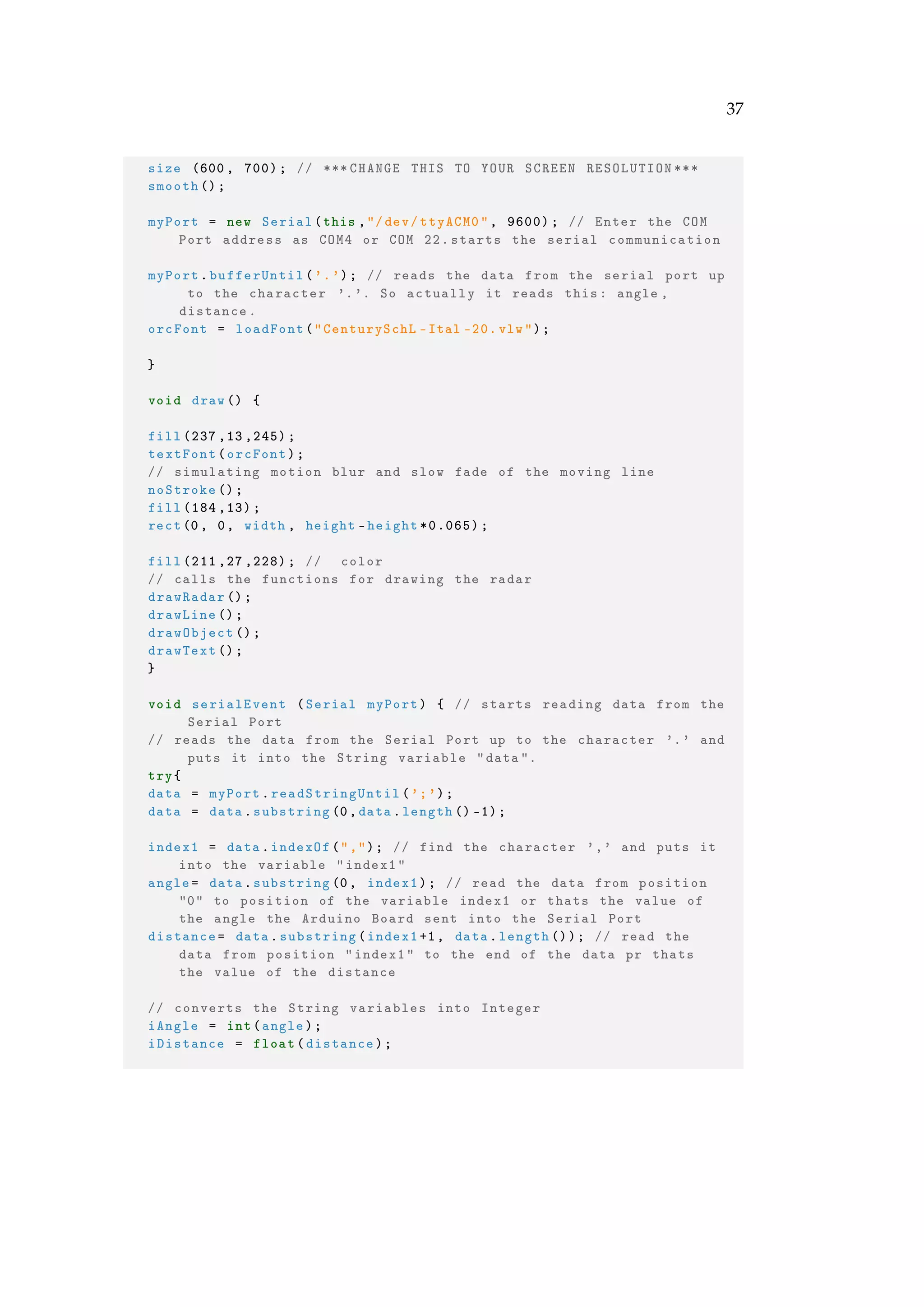
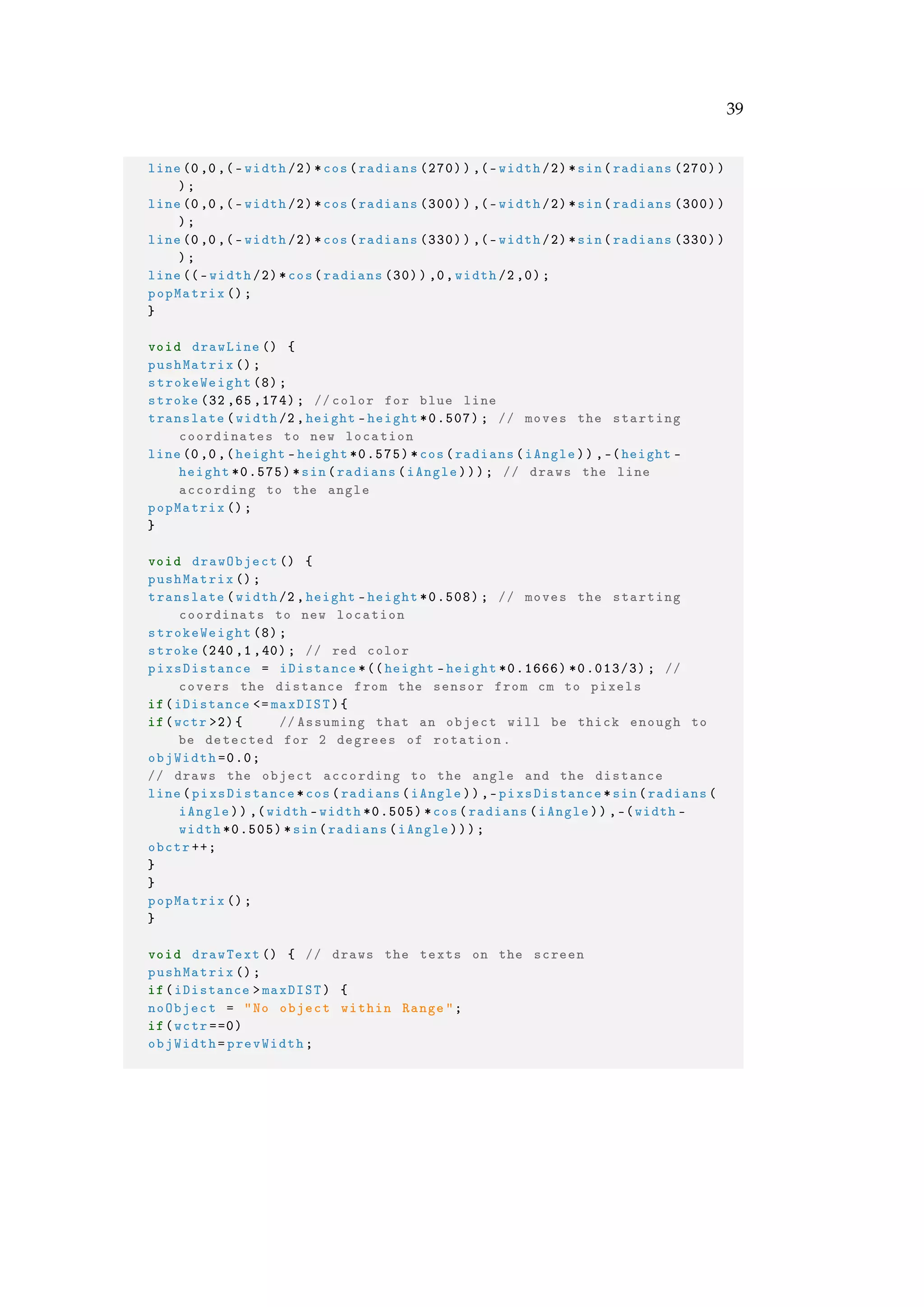
![D Appendix B : Processing Code
The Java code that we ran in Processing is given below :
Listing D.1: The Processing Code
/* Arduino Radar Project
* 1.1 [Final and complete]
* Initialise every variable to null value to avoid null pointer
exception
*/
import processing.serial .*; // imports library for serial
communication
import java.awt.event.KeyEvent; // imports library for reading the
data from the serial port
import java.io.IOException;
Serial myPort; // defines Object Serial
// defines variables
String angle="";
String distance="";
String data="";
String noObject="";
float pixsDistance =0.0;
int iAngle =0;
float iDistance =0.0;
int index1 =0;
int index2 =0;
int objCount=0,obctr =0;
PFont orcFont;
float angFlag =1.0;
float prevAng =0.0, deltaAng =0.0;
float maxDIST =50.0; //max distance of object in cms
int wctr =0;
float objWidth =0.0, prevWidth =0.0;
void setup() {
36](https://image.slidesharecdn.com/sonarprojectreport-170128210420/75/Sonar-Project-Report-41-2048.jpg)

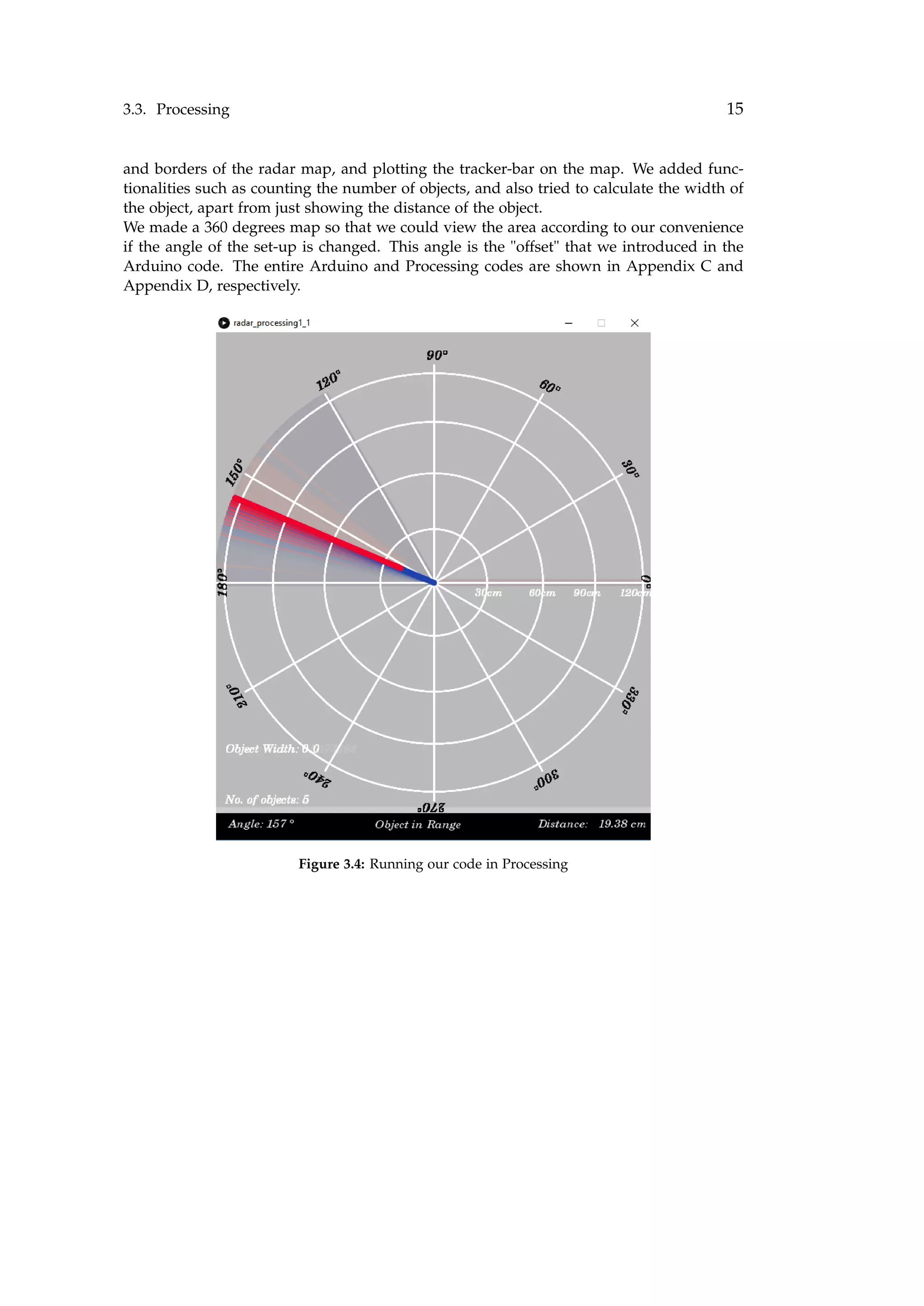
This document is a report on an object detection system using an ultrasonic sensor and micro-servo motor controlled by an Arduino board. The system uses an HC-SR04 ultrasonic sensor mounted on a micro-servo motor to detect objects within a 4m radius by sweeping the sensor's field of view. The Arduino receives distance measurements from the sensor and sends them to a computer via serial communication for graphical display. The report describes the components used, circuit diagrams, code explanations, calibration process and observations made with the system.
An introduction to the project 'Object Detection using SONAR based system' by students under guidance.
Details on the project theme, components used (HC-SR04, Arduino), and a table of contents for the report.
Introduction outlining the project approach, components selected (Arduino UNO), operational details of Arduino.Description of the HC-SR04, its operational principles, features, and limitations in detecting stationary objects.
Details about the Micro-Servo Motor used for rotating the ultrasonic sensor for a wider field of view.
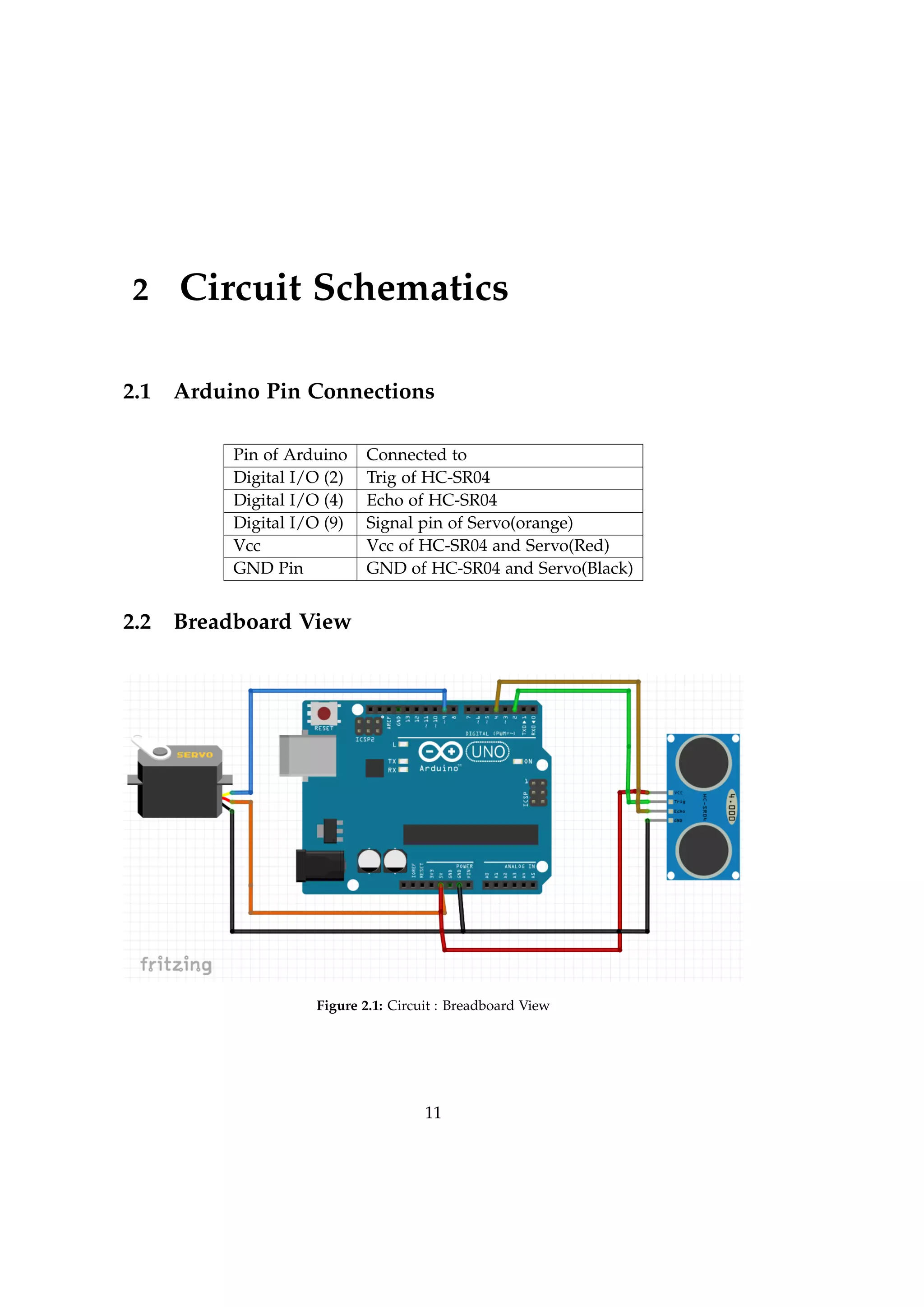
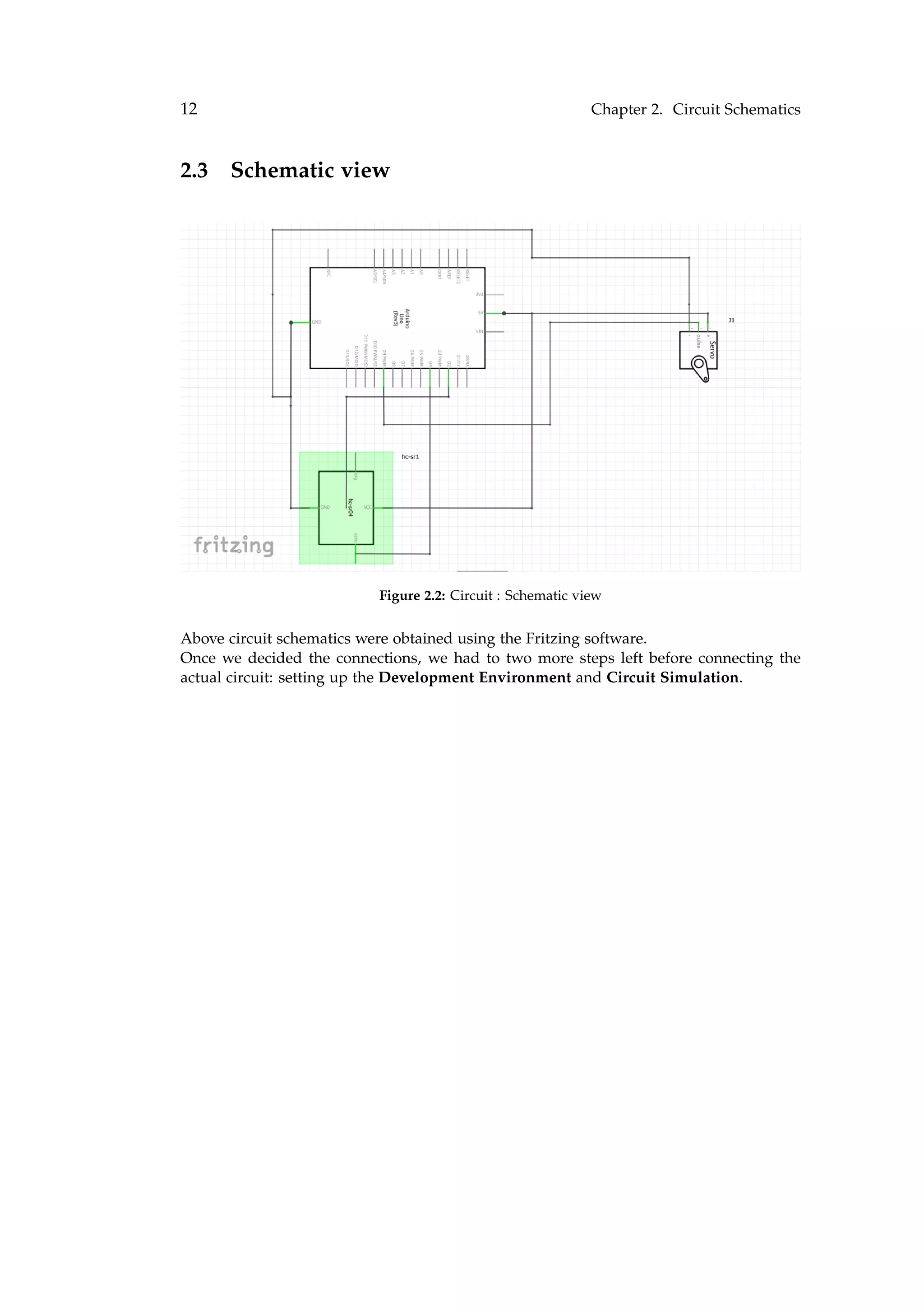
Descriptions of the pin connections and circuit schematics with images illustrating each setup.
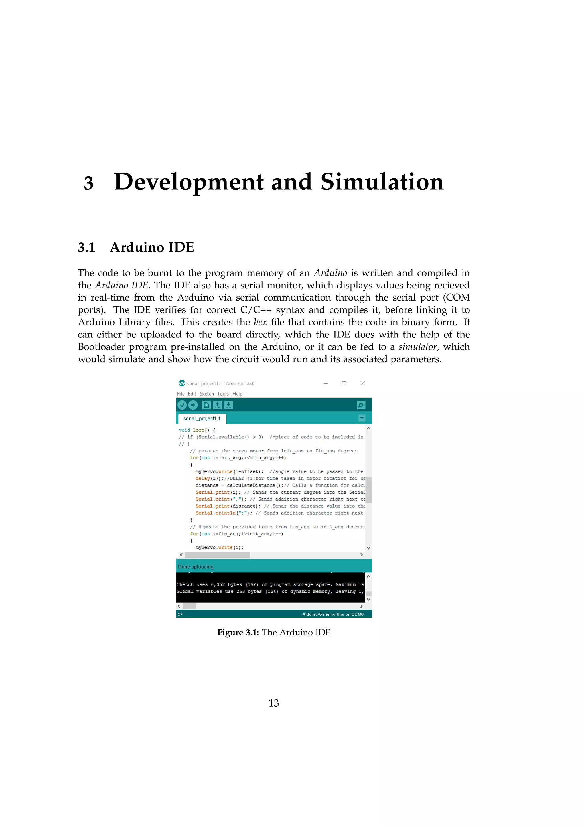
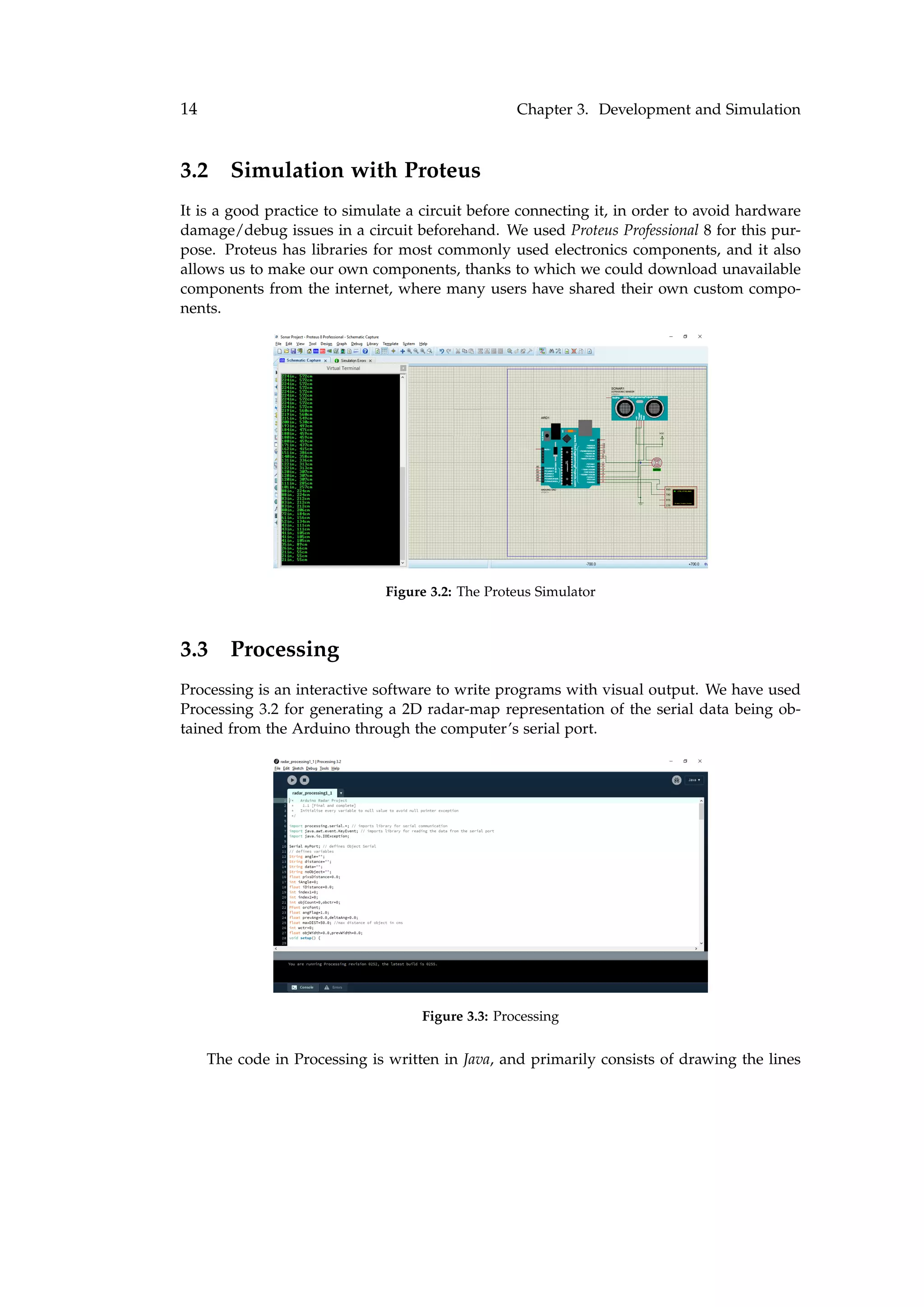
Integration of Arduino IDE, circuit simulation in Proteus, and processing for visual output.
Outline of the Arduino code logic for the project and introduction to Processing for visual output.Challenges in sensor measurement, calibration of distance calculations to achieve accurate data.
Comparative graphs displaying measurement errors across different object types regarding distance.
Identified issues with measurement accuracy, proposed solutions to optimize sensor reading times.
Summary of challenges experienced with HC-SR04 and suggestions for utilizing different sensors for accuracy.
Acknowledgments, team members, and code listings for Arduino and Processing.


![ANPARA THERMAL POWER STATION[1] sangam.pdf](https://cdn.slidesharecdn.com/ss_thumbnails/anparathermalpowerstation1sangam-251121115219-9261cde4-thumbnail.jpg?width=640&height=640&fit=bounds)


